
VISUAL CONTRACTS
A Way to Reason About States and Cardinalities in IT System Specifications
José D. De la Cruz, Lam-Son Lê, Alain Wegmann
School of Computer and Communications Sciences,
Ecole Polytechnique Fédérale de Lausanne, CH-1015 Lausanne, Switzerland
Keywords: Visual Languages, UML, Specification, Conceptual Modeling, Hierarchical Systems, Model-Checking.
Abstract: Visual modeling languages propose specialized diagrams to represent behaviour and concepts necessary to
specify IT systems. As a result, to understand a specification, the modeller needs to analyze these two types
of diagrams and, often, additional statements that make explicit the relationships between them. In this
paper, we define a visual contract notation that integrates behaviour and concepts. Thanks to this notation,
the modeler can specify, within one diagram, an action and its effects on the specified IT system. The
notation semantics is illustrated by a mapping to Alloy, a light weight formal language.
1 INTRODUCTION
The creation of the specification of an IT system is a
complex task that requires the division of the
specification into smaller, partial descriptions (e.g.
conceptual class diagram, state machine diagram,
etc.) portraying each a perspective of the system. In
this paper, we focus on the division between
conceptual and behavioural diagrams in graphical
specifications. When such separation is made, four
main drawbacks appear: First, there are not precise
relationships among the different diagrams.
Secondly, each kind of diagram is expressed using
its own language. Third, the constraints are generally
expressed in yet another language. Fourth, the
system specification cannot be easily validated.
Our concern is how to “glue back” the partial
system descriptions together in order to obtain a
holistic view of the system that can be validated. We
propose a notation that integrates conceptual
specification together with behavioural specification.
The goals are to facilitate a) the reasoning of the
modellers in the terms of actions/services, and b) to
enable the model checking of the specification. We
map our visual notation onto the formal language
Alloy (Jackson, 2002) in order to validate its
soundness.
Throughout the paper we show the example of an
IT system (
BoardingITSystem) that controls the
boarding process of passengers to a plane. Initially,
the plane is empty but the passengers have already
checked-in at the company ticket counter. Then the
system processes the requests from passengers that
are ready for going onboard: passengers’ boarding
passes are processed one by one until the plane’s
maximum capacity is reached. As a safety rule, none
of the passengers can board or disembark more than
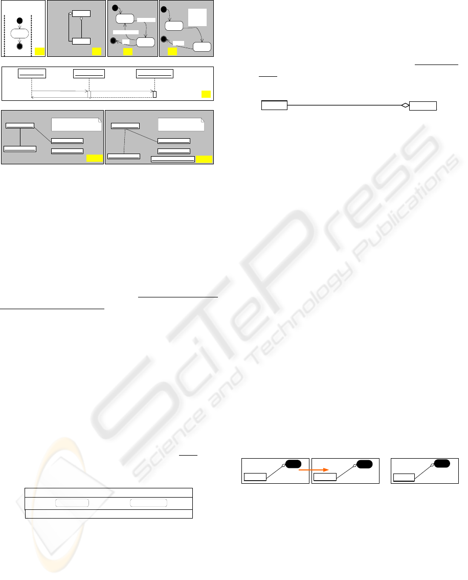
once. Figure 1 illustrates this example using the
UML notation (OMG, 2005).
Section 2 defines visual contracts and their
semantics (in Alloy). Section 3 presents the
BoardingITSystem example using our visual
contract notation. Section 4 is the state of the art.
2 VISUAL CONTRACT
We define Visual Contract (VC) as the visual
model that represents both the pre and the post
conditions for an action as well as the changes
between the two. Our visual contract notation is
developed in the context of SEAM (Systemic
Enterprise Architecture Methodology), a method
designed for reasoning about business and IT
alignment (Wegmann et al, 2005).
In our approach, we model the behaviour
together with the state of the systems. Our modelling
ontology is based on RM-ODP(ISO/IEC & ITU-T,
1998) and on our formalization of it (Le &
Wegmann, 2005).
298
D. De la Cruz J., Lê L. and Wegmann A. (2006).
VISUAL CONTRACTS - A Way to Reason About States and Cardinalities in IT System Specifications.
In Proceedings of the Eighth International Conference on Enterprise Information Systems - ISAS, pages 298-303
DOI: 10.5220/0002462402980303
Copyright
c
SciTePress
Plane
a)
Person_1:PersonPerson_1:Person
f)
g)
Activity diagram
Board: Sequence diagram
Snapshot diagram – After Board Snapshot diagram – Before Board
Person
b)
Class diagram
Plane
1
1..*
State diagram State diagram
Plane_1: Plane
Person_2:Person
Person_3:Person
reponse_OK: Response
Board
e)
User_1:User
Plane_1:Plane Person_1:Person
Response
Ask_for_Board ()
Plane_1: Plane
Person_2:Person
Person_3:Person
time = after Boardtime = before Board
d)
notFull
full
[number of
person
>=
capacity]
[crash]
class Plane
c)
offBoard
onBoard
[disembark_OK]
[board_OK]
[kill]
class Person
board_OK
passenger
BoardingITSystem
passenger_1
passenger_1
candidate_1
passenger_2
BoardingITSystem
BoardingITSystem
BoardingITSystem BoardingITSystem
1
1..*
checkedIn
Figure 1: A partial UML specification for activity Board
of system BoardingITSystem.
A system is modelled as a RM-ODP object that
we call working object. Working objects can be
specified as whole or as composite. A working
object as whole is described atomically. Only the
externally visible behaviour is described using a
model-based description (Schätz et al, 2002). A
working object as composite is described as a set of
component working objects that collaborate
together. In visual contracts, we consider only
working objects as whole.
Working objects as whole are described in terms
of information objects, set associations and localized
actions.
2.1 Information Objects
An Information Object (IO for short) captures the
type and the possible states of the concepts
necessary to describe the observed system.
For example, Figure 2 represents the IO
Person
that captures the information of a person in the real
world. The attribute
Boarded captures the state of a
Person in relation with the Plane she wants to
board. All IOs include an identity attribute
Id.
Person
offBoard onBoard
Id
Boarded
Figure 2: Information Object representation.
2.2 Set-Associations
We claim that when reasoning with graphical
models our minds use instances implicitly.
Set-associations (SA) captures information
about these instances. As set-associations relate IOs,
it means that these instances exist within a context.
For example a set-association between a Plane and a
Person can represent a person that is either
offBoard or onBoard. This is illustrated in Figure 3.
For practical reasons, we avoid drawing the single
instances (extensional form, like in the object
diagrams of UML), and we use instead cardinality
and state information of the set of instances. We call
this the intensional form.
Plane
#1
passenger_List
Person
#4
offBoard
Figure 3: SEAM representation of 4 passengers using
instance cardinalities.
As illustrated in Figure 3, a SA requires a name
(
passenger_List), a referring instance cardinality
(
#1), a set of referred instances cardinality (#4), and
a state (
offBoard).
2.3 Actions
As illustrated in Figure 1, an action can be modelled
in UML by a set of quasi-orthogonal diagrams (that
can be related to each other via OCL). In contrast,
our visual contract diagrammatically describes in a
single diagram an action and its effects.
An action specifies the effects of system’s
reactions to a set of events for a given system state.
When we consider a given action A (A), we
describe the set of predicates for the initial
conditions (P) that will guarantee that the final state
(Q) is reached, as expressed in (Hoare, 1969):
{ P } A { Q } (1)
Since state information of objects is represented
at the set associations, the change of global state is
equivalent to the sum of changes in set associations:
changes of cardinality and of state.
Figure 4 and Figure 5 represent diagrammatically
changes due to actions
op1 and op2, respectively.
op1
Person
op1
Person
#1
c)
a)
op1
Person
#2
b)
#1 -> #2
onBoard onBoard onBoard
Figure 4: Action changes cardinality of set-associations.
On the left side the initial (a) and final (b) conditions. In
(c) SEAM notation for representing changes.
In Figure 4.a there is only a single instance of
type
Person. After op1, there are two instances of
the same IO, as shown in Figure 4.b. The state of the
instances does not change. The Figure 4c is the
SEAM equivalent to the evolution from 4.a to 4.b.
In Figure 5, we illustrate a state change (without
cardinality changes). Initially, the SA
selected
includes one instance of IO
Person that is offBoard
VISUAL CONTRACTS - A Way to Reason About States and Cardinalities in IT System Specifications
299
(5.a). At the end, this same person is onboard
(5.b). Figure 5.c represents the evolution from 5.a
to 5.b.
Op2
Person
op2
Person
offBoard
c)
a)
op2
Person
onBoard
b)
offBoard ->
onBoard
#1 #1
#1
Figure 5: Action changes state of instances in set-
associations.
Figures 4.c. and 5.c introduce the «change»
operator (Æ), central in our approach. As a
corollary, we may say that what is not shown as
changing in the specification of an action is
considered to remain unchanged.
2.4 Other Modeling Constructs
We can reason about systems because we can see
how actions change the instances. Therefore, it is
fundamental to model the lifecycles of the instances
(to understand which instances exist and when). A
context of existence of an instance is the temporal
frame where an instance or a set of instances exist.
Our semantics for the context of existence is similar
to UML composition/ aggregation, so we will use
the UML notation (black/hollow diamond).
Given that all instances exist in a context, there is
a “first context” for each system. It is the model
element Myself. This element represents the “root”
of all behavioural and conceptual
information
describing the system. The double nature of this
model element is represented by a symbol that
combines an IO and an action:
Myself
We also define a special kind of information
object: the parameter. Parameters are necessary to
represent the communication through the boundary
of the system or through action boundaries. The
stereotype can be «Par In» or «Par Out» depending
on whether it is an input or an output parameter.
3 EXAMPLE: THE PLANE
BOARDING CONTROL
SYSTEM
In this Section, we present the visual contract that
corresponds to Figure 1. First we introduce the
necessary information objects (Section 3.1). We then
define the operations
Init and CheckIn (Section
3.2) and then
Board (Section 3.3). Only a normal,
correct case of behaviour is shown in this paper.
For each diagram we present, we define the
Alloy equivalent. Alloy is a light weight model-
checkable specification language that we use to
define the semantics of our notation.
3.1 Definition of Information
Objects
BoardingITSystem
# *
capacity
Plane
Myself
offBoard_passenger_List
#1
Person
onBoard offBoard
id
# *
onBoard_passenger_List
Boarded
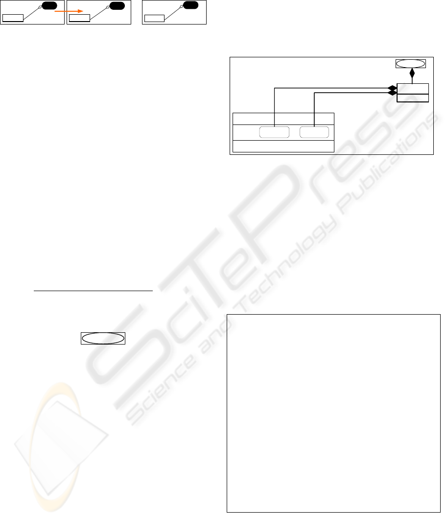
Figure 6: SEAM notation for data definitions for the
BoardingITSystem.
For sake of simplicity, the system
BoardingITSystem knows one Plane only. SEAM’s
representation, shown in Figure 6, can be read as
follows: In the system (i.e.
Myself), there is the
knowledge of one Plane with a
capacity. This
Plane has two passenger_List that can contain
multiple passengers each; one is for the
passengers
that have checked-in (
offBoard) and the other one
for the ones that have effectively boarded the
Plane (
onBoard).
The Alloy equivalent is shown in figure 7.
sig Time { }
sig Person { id: Int }
fact uniqueId{
all p,q:Person|p!=q => p.id!=q.id }
one sig Plane {
capacity: Int,
onboard_passenger_List:
set Person->Time,
offboard_passenger_List:
set Person -> Time }
{ int capacity > 0
all t: Time |
int capacity >=
#onboard_passenger_List.t +
#offboard_passenger_List.t
all t: Time | no p: Person |
p in onboard_passenger_List.t and
p in offboard_passenger_List.t
}
Figure 7: Partial Alloy specification for action Board.
The Alloy can be read as follows: a set of
ordered time points are defined (
sig Time); a set of
Person are defined (sig Person) with a unique
ICEIS 2006 - INFORMATION SYSTEMS ANALYSIS AND SPECIFICATION
300
identifier (
fact uniqueID). We define also a Plane
that has a
capacity and 2 lists: onboard_Passenger
_List
and offBoard_Pass enger_List. These lists
include a relation between a person and a time point
(necessary to simulate the execution sequence).
Some invariants are defined in the plane: the
capacity is never exceeded, and nobody can be in
both lists at the same time.
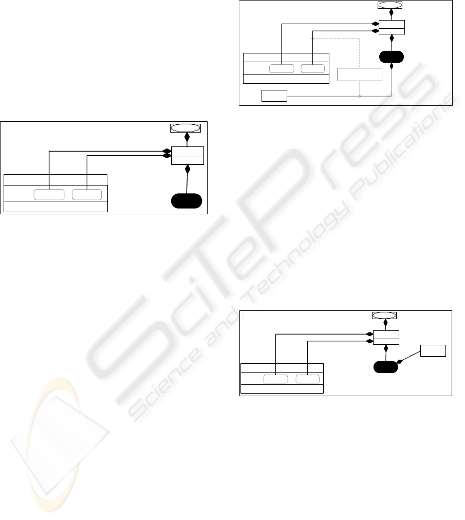
3.2 Operations Init & CheckIn
Figure 8 shows the SEAM visual contract for
operation
Init. It states that the number of Person
in both
passenger_List (offBoard, onBoard) is set
to zero.
Init
BoardingITSystem
# * --> #0
capacity
Plane
Myself
#1
Person
onBoard offBoard
id
# * --> #0
offBoard_passenger_List
onBoard_passenger_List
Boarded
Figure 8: The SEAM contract of Init: the cardinality of the
passenger_List SA changes.
The cardinality of each set-association that links
passenger_List to Person goes from some initial
value (any, symbolized by the character ‘*’) to 0. In
the practice, this means erasing all instances of
Person linked to both
passenger_List
(
offBoard, onboard).
The action
checkIn, not presented in this paper,
assigns instances of Person to the
offBoard_passenger_List.
3.3 Operation Board
The specification of action Board is the following:
“The plane preconditions are: a) an input parameter
represents the identifier of the person that desires to
go on board, b) this person has already checked-in,
and c) the number of people onboard has not reached
the maximum capacity of the plane. The post
condition is that the person is now onboard. In
addition, the system emits a message confirming the
entry of the person into the plane”.
Before creating the Visual Contract for action
Board, we illustrate the action by making two
snapshots: one before and one after the operation
Board. The situation would be as shown in Figures 9
and 10, respectively.
In the precondition, there is an instance of
Id_Person that is considered as valid. The valid
condition is defined by a constraint in the diagram:
the
Id_Person should correspond to the id of only
one Person that has already checked-in (she is in
the
offBoard_passenger_List).
Board
Id_Person
<<Par In>>
#1
valid
Valid = one (Persoin.id
== Id_Person)
BoardingITSystem
# *
capacity
Plane
Myself
offBoard_passenger_List
#1
Person
onBoard offBoard
id
# *
onBoard_passenger_List
Boarded
Figure 9: Precondition for action Board.
During the action Board, the parameter
Id_Person is validated and the corresponding
instance of
Person in the offBoard_
passenger_List
is referenced by the action via the
SA
selected.
In the post condition, Figure 10, the selected
instance of
Person will be transferred to the
onBoard_passenger_List (supposedly the one that
has been admitted in the precondition); the
cardinality change in the corresponding SA
symbolizes this. Simultaneously, the
offBoard_passenger_List is decremented by one.
Finally, a Response parameter is emitted,
indicating the success of the operation (represented
by the SA
Greetings_Response).
Response
<<Par Out>>
#1
Greetings_Response
Board
BoardingITSystem
# * -> # (*+1)
capacity
Plane
Myself
offBoard_passenger_List
#1
Person
onBoard offBoard
id
# * -> # (*-1)
onBoard_passenger_List
Boarded
Figure 10: Post condition of action Board.
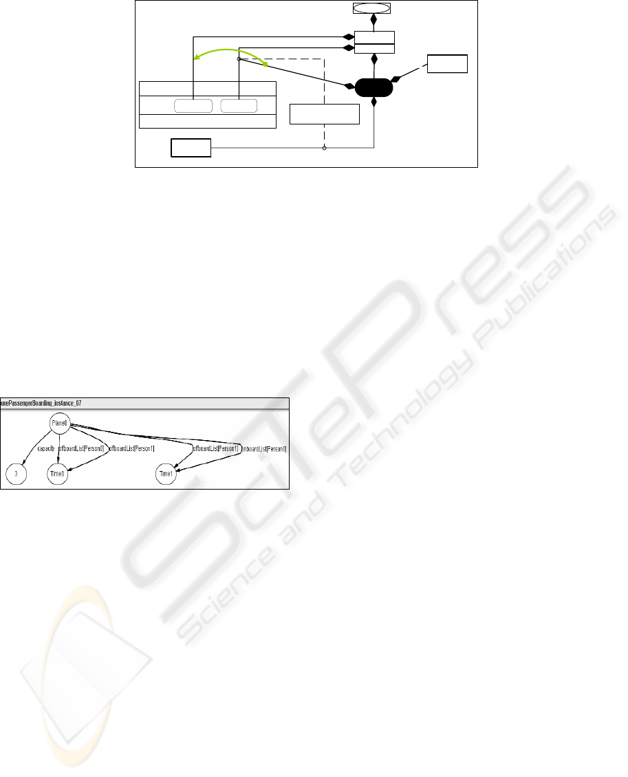
The whole visual contract is shown in Figure 11.
Here we make explicit the changes and the instances
involved, in order to avoid misunderstandings. The
instance of the
offBoard_passenger_List that
corresponds to the
Id_Person is represented by the
SA
selected, that exists in the context of action
Board. Remark that this temporary information does
appear neither in the pre nor in the post condition.
Notice also that the constraint regarding the
Plane capacity has become a guard for a transfer of
the instance
selected of IO Person from
offBoard_passenger_List onto the onBoard_
passenger_List
.
VISUAL CONTRACTS - A Way to Reason About States and Cardinalities in IT System Specifications
301
Board
Id_Person
<<Par In>>
#1 -> #0
valid
Valid = one (Persoin.id
== Id_Person)
BoardingITSystem
# * -> # (*+1)
capacity
Plane
Myself
offBoard_passenger_List
#1
Person
onBoard
offBoard
id
# * -> # (*-1)
onBoard_passenger_List
selected
Response
<<Par Out>>
#0 -> #1
Greetings_Response
[notFull]
notFull = onBoard_passenger_List.cardinality < Aircraft.capacity
Boarded
Figure 11: Visual contract for action Board. It illustrates the «change» operator.
The Figure 12 illustrates the evolution of state of
the IT system during the contract execution. It is the
result of the execution of the Alloy code presented
below. It shows a scenario where the plane has two
people (
Person0, Person1) in the offBoard_
passenger_List
before the action execution (at
Time0). One passenger (Person1) actually boards the
plane, as can be seen in the nodes that represent the
state after the action execution (at
Time1). The
person
Person0 has changed to the
onBoard_passenger_List.
Figure 12: Result of simulating the action Board in the
Alloy analyzer. Time0 and Time 0 are the moment before
and after the action takes place.
4 RELATED WORK
UML (OMG, 2005) is the industry standard in
object-oriented analysis and design. UML creating
heterogeneous models made up of different
diagrams and notations. In our approach, we try to
minimize the number of diagrams to one by
representing conceptual and behavioural
specifications together. Our syntax is comparable to
UML –in order to improve the usability— however
semantics are totally dissimilar. We can say that
VCs are complementary to UML diagrams.
One of the challenges we face is how to express
the relationships between instance and types in
conceptual modelling. UML proposes the use of
separate diagrams: class and object (OMG, 2005).
Heckel (Heckel & Sauer, 2001) deals with types and
instances in collaboration diagrams. While these
approaches represent static information, our goal is
to represent how actions change information.
The use of contracts allowed validating
implementations of object-oriented designs (Helm et
al; 1990; Meyer, 1992). The use of contracts to
specify actions, interactions, use cases, and activities
is presented in (D'Souza & Cameron Wills, 1998;
Rik Eshuis, 2001; Stevens, 2001; Wirfs-Brock et al,
1990). However, most of the work has been done
mostly using OCL and textual logics. Only recently,
two research groups (Lohmann et al, 2005; De la
Cruz et al, 2005) have proposed independently the
concept of “visual contracts”. The first focuses on
automatic generation of code that reinforces the
compliance of the applications of the IT system with
the constraints and business rules whereas the latter
focuses on conceptual modelling and IT system
specification.
The graph transformation (GT) languages like
QVT (OMG, 2005) , VPM (Varro & Pataricza,
2003) and the one proposed by Heckel (Heckel &
Sauer, 2001) are syntactically similar to our
contracts because a) we use UML-like notation and
b) the contracts are also executed according to a
pattern-matching oriented philosophy. However,
they use OCL and are used mostly for
transformation among languages –e.g. class
diagrams to java code, statecharts to sequence
diagrams, etc. — at the metamodel level. They are
not used as languages for specification but for
extraction/transformation from models that should
generate object-oriented code. Their primary goal is
to guarantee well-formedness and translatability, and
not to support reasoning about actions/services and
system evolution. Besides, our approach is
declarative whereas many of the GT languages are
mostly operational/ imperative. Our approach is
complementary to these UML-based initiatives.
ICEIS 2006 - INFORMATION SYSTEMS ANALYSIS AND SPECIFICATION
302

5 CONCLUSIONS AND FUTURE
WORK
In order to define visual contracts, we extend the
traditional interpretation of the association and we
integrate diagrams that are usually considered as
separate. We define the concept of set associations
that capture the existence of instances of concepts in
a given context. We use these set associations to
relate information objects (our term for concepts) to
information objects but also actions to information
objects. To represent the pre and the post condition
on a single diagram, we define a new graphical
symbol to express the change of cardinality or state.
Our visual contracts addressed the four issues
raised by the separation of conceptual and
behavioral diagrams for modeling actions. First,
differente descriptions were put along in a single
diagram; our visual contracts include structure, state,
communication & synchronization, action/activity
and constraint information. Secondly, the proprietary
languages of each notation were harmonized with
each other by our semantics. Third, constraints were
illustrated as logic guards for changes in the visual
contracts. Fourth, the diagram themselves can be
used to reason about the system actions.
We also reconcile and integrate the formal
methods that allow us model-checking and
simulating our models. The mapping between the
visual contracts and a model-checkable language as
Alloy is useful to validate the specification model
before a real/complex implementation is done.
Our future work includes testing and improving
the usability of the notation, developing tool support
that translates automatically the visual contract into
the Alloy code, and the integration of this feature
into our CAD tool (Le & Wegmann, 2005), as well
as formalizing the model-checking capability. We
plan also to build a UML to SEAM translation tool.
REFERENCES
De la Cruz, J. D., Wegmann, A., & Regev, G. (2005).
Expressing Systemic Contexts in Visual Models of
System Specifications. In T. Bui & A. Gachet (Eds.),
Proceedings of the Workshop on
Context Modeling and Decision Support, CONTEXT-
05 Workshops (Vol. CEUR 144). Retrieved October
31, 2005, from http://CEUR-WS.org/Vol-
144/04_deLaCruz.pdf
D'Souza, D. F., & Cameron Wills, A. (1998). Objects,
components, and frameworks with UML: The
Catalysis approach (1 ed.): Addison Wesley
Longman, Inc.
Heckel, R., & Sauer, S. (2001). Strengthening UML
Collaboration Diagrams by State Transformations.
Paper presented at the FASE 2001, Genova, Italy.
Helm, R., Holland, I. M., & Gangopadhyay, D. (1990).
Contracts: Specifying Behavioural Compositions in
Object-Oriented Systems. Paper presented at the
OOPSLA/ECOOP 1990, Ottawa, Canada.
Hoare, C. A. R. (1969). An Axiomatic Basis for Computer
Programming. Communications of the ACM (CACM),
12(10), 576-580.
ISO/IEC, & ITU-T. (1998). Recommendation X.901,
X.902, X.903, X.904, "Open Distributed Processing -
Reference Model" (Recommendation): ISO and ITU-
T.
Jackson, D. (2002). Alloy: a lightweight object modelling
notation. ACM Trans. Softw. Eng. Methodol., 11(2),
256-290.
Le, L. S., & Wegmann, A. (2005). Definition of an Object-
Oriented Modeling Language for Enterprise
Architecture. Paper presented at the HICSS'05,
Hawaii, USA.
Lohmann, M., Sauer, S., & Engels, G. (2005). Executable
Visual Contracts. Paper presented at the IEEE
VL/HCC’05, Dallas, Texas, USA.
Meyer, B. (1992, Oct.). Applying "Design by Contract".
IEEE Computer, 25, 40-51.
OMG. (2005). Unified Modeling Language (UML), from
www.omg.org
Rik Eshuis, R. W. (2001). A Real-Time Execution
Semantics for UML Activity Diagrams. Paper
presented at the FASE 2001, Genova, Italy.
Schätz, B., Pretschner, A., Huber, F., & Philipps, J.
(2002). Model-based development of embedded
systems. In J.-M. Bruel & Z. Bellahsene (Eds.),
Advances in Object-Oriented Information Systems,
OOIS 2002 Workshops (Vol. LNCS 2426, pp. 298-
312). Montpellier, France: Springer.
Stevens, P. (2001). On Use Cases and Their Relationships
in the Unified Modelling Language. Paper presented at
the FASE 2001, Genova, Italy.
Varró, D., & Pataricza, A. (2003, Aug.). VPM: A visual,
precise and multilevel metamodeling framework for
describing mathematical domains and UML. Software
and Systems Modeling, 2(3), 187-210.
Wegmann, A., Balabko, P., Le, L.-S., Regev, G., &
Rychkova, I. (2005). A Method and Tool for Business-
IT Alignment in Enterprise Architecture. Paper
presented at the CAiSE'05, Porto, Portugal.
Wirfs-Brock, R., Wilkerson, B., & Wiener, L. (1990).
Designing Object-Oriented Software (1 ed.).
Englewood Cliffs: Prentice Hall.
VISUAL CONTRACTS - A Way to Reason About States and Cardinalities in IT System Specifications
303
