EXEMPLAR-BASED INPAINTING WITH ROTATION INVARIANT
PATCH MATCHING
Ji
ˇ
r
´
ı Boldy
ˇ
s
L3i, University of La Rochelle
Av. Michel Cr
´
epeau, 17042 La Rochelle cedex 1, France
Bernard Besserer
L3i, University of La Rochelle
Av. Michel Cr
´
epeau, 17042 La Rochelle cedex 1, France
Keywords:
Movie restoration, image reconstruction, exemplar-based inpainting, rotation invariance, moment invariants.
Abstract:
In this paper, we propose a novel approach to patch matching in exemplar-based inpainting. Our field of
concern is movie restoration, particularly scratch concealment. Here we want to focus on a single frame (still
image) inpainting. Exemplar-based approach uses patches from the known areas and copies their content
to the damaged area. In case of irregular texture, there might be no patches available, so that the result
would be visually acceptable. One way to increase the number of available patches is to rotate them. In
most of the exemplar-based approaches, a target patch is not complete and a source patch has to be rotated
and compared at every single angle. We overcome this inefficiency using a clue image, which comes from
previous processing stages. We use moments of patches from this clue image, normalized to rotation, to reject
apparently dissimilar patches, and to calculate the approximate angle of rotation, which has to be performed
only once. In this paper, we provide justification for this simplification. We have no ambitions to provide a
complete inpainting algorithm here.
1 INTRODUCTION
This paper contributes to the field of movie restora-
tion. Old movies suffer from many defects rising from
their extensive usage and from film instability. One of
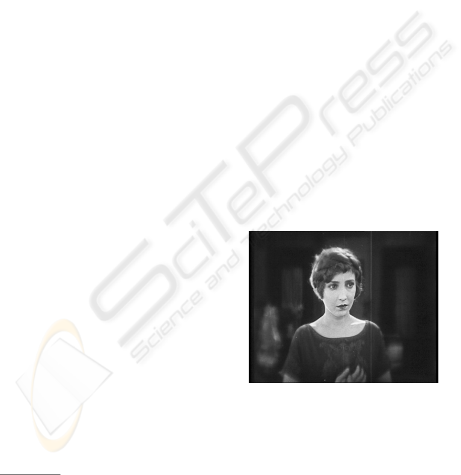
the most frequent defects are scratches. One example
is shown in Fig. 1. Scratch concealment is our main
research objective.
Provided there is no need to reconstruct fine texture
or grain, methods based on solving partial differential
equations (PDE’s) can be used, see e.g. (Bertalmio
et al., 2000; Chan and Shen, 2001; Chan et al., 2002).
In movie restoration, it is also important to reconstruct
film grain and noise. Therefore, an exemplar-based
approach of (Criminisi et al., 2004) is more appro-
priate. Paper (Bertalmio et al., 2003) is an example
of method where the main structure is inpainted by
a PDE method and a method for texture synthesis is
used to reconstruct the fine details. Sometimes, film
scratches do not damage information from all dye lay-
ers. It results in color corruption where, to some ex-
1
J. Boldy
ˇ
s is also with the Institute of Information The-
ory and Automation, Academy of Sciences of the Czech
Republic, Pod vod
´
arenskou v
ˇ
e
ˇ
z
´
ı 4, 182 08 Prague 8, Czech
Republic (currently on leave).
Figure 1: Example of a typical scratch. The picture is from
the movie The Lost World, 1925. By courtesy of Lobster
Films.
tent, the texture remains. In that case, Bayesian re-
construction approach of (Joyeux et al., 2002) can be
applied.
Exemplar-based inpainting works well in cases of
regular textures, where the missing information can
be re-filled by suitable patches from the known area.
If a unique non-repetitive structure is damaged, there
115
Boldyš J. and Besserer B. (2006).
EXEMPLAR-BASED INPAINTING WITH ROTATION INVARIANT PATCH MATCHING.
In Proceedings of the First International Conference on Computer Vision Theory and Applications, pages 115-120
DOI: 10.5220/0001376801150120
Copyright
c
SciTePress
are no patches in the neighborhood, which could be
used without getting a result with visible artifacts.
It is possible to increase the number and variety of
available patches by their photometrical or geometri-
cal transformation. The source patch (the patch from
the known area) can be rotated, scaled, flipped, or
its intensity can be adjusted to better match the tar-
get patch (the patch being reconstructed). There is a
large amount of literature using a certain degree of in-
variance in matching problems (Zitov
´
a and Flusser,
2003). For image reconstruction, these techniques
have been adopted in (Drori et al., 2003), where five
scales and eight orientations of the patches are tested
or in (Zhang et al., 2004), where projective transfor-
mation of patches are estimated.
This paper focuses on the problem of rotation in-
variance in patch matching. Rotating the source patch
several times and testing the proximity of each ori-
entation to the target patch is a very time consuming
task. In matching problems from other fields of image
processing, moment invariants are often used to per-
form the match effectively (Zitov
´
a and Flusser, 2003).
In exemplar-based image reconstruction, matching
based on moments is normally impossible, since the
target patches are incomplete and moments are cal-
culated from the whole patch. Our scratch inpainting
algorithm works in multiple resolutions. Inpainting
results from previous stages are refined afterwards.
Therefore, the mentioned difficulty can be overcome
by applying the moment invariants to patches from a
pre-inpainted image.
Patch matching and orientation estimation is much
faster using moment invariants. This is a novel ap-
proach, opening new possibilities in exemplar-based
reconstruction. Using the clue image for matching
patches containing fine details has to be justified,
which is a part of this paper.
This paper focuses solely on the particular prob-
lem of rotation invariance in exemplar-based inpaint-
ing. The method has been tested on gray-level im-
ages, however extension to color images should be
straightforward. Detailed explanation of the inpaint-
ing algorithm is not our objective. Although, scratch
inpainting is a temporal problem, here we limit our-
selves to the reconstruction of a single frame.
2 EXEMPLAR-BASED
INPAINTING ALGORITHM
In this section, exemplar-based inpainting as de-
scribed in (Criminisi et al., 2004) is shortly explained.
This serves as a starting point for a brief explanation
of our algorithm. The main motivation for modifi-
cations of the original exemplar-based algorithm was
to avoid artifacts in the middle of the inpainted do-
main, rising from lack of interaction between patches
copied to opposite sides of the unknown area. Images
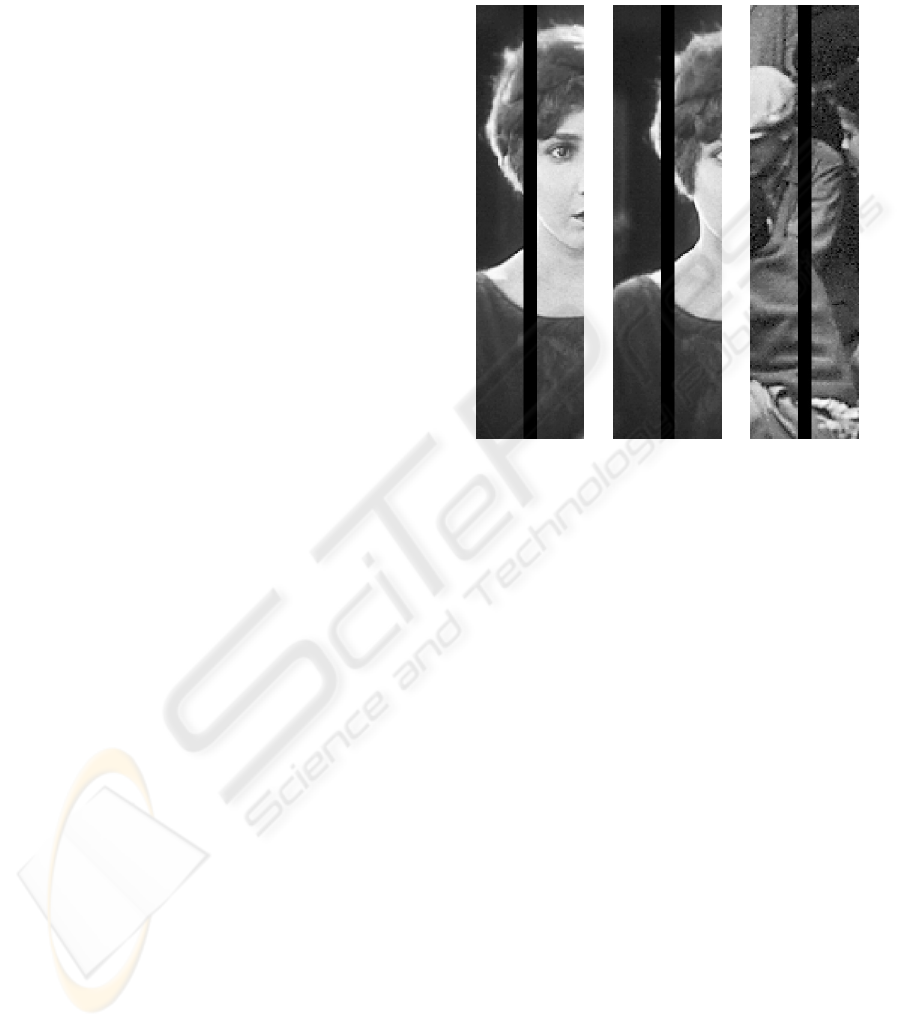
shown in Fig. 2 are used in this paper. The scratches
are made artificially.
Figure 2: Images used for testing our algorithm. The
scratches are made artificially.
Exemplar-based inpainting algorithm according to
(Criminisi et al., 2004) works as follows: Pixels along
the border of the inpainted domain are sorted accord-
ing to priority, which is based on structure saliency
and on confidence of already inpainted pixels. A
block of pixels (due to later usage of rotation invari-
ance, we call it a patch) around the first pixel in the list
is called a target patch. A source patch of the same
size as the target patch is searched in a neighborhood
of a pre-determined size. The best match based on the
known pixels (or its part) is copied to the position of
the target patch. The priorities are updated and the
whole process is repeated. The algorithm is demon-
strated in Fig. 3.
The borders propagate inside the inpainted domain
and meet in the middle of it. Since there is no commu-
nication between them, it results in artifacts, examples
of which are shown in Fig. 4.
Our main improvements to the algorithm proposed
in (Criminisi et al., 2004) are using multiresolution,
clue images and invariant patch matching. Multireso-
lution helps to inpaint textures with different charac-
teristic sizes. It also partially alleviates artifacts pro-
duced in earlier lower-resolution stages. The image is
decomposed into Laplacian pyramid and the lowest-
resolution image is inpainted by the PDE method of
(Chan and Shen, 2001). The result is upsampled and
used as a clue in the next finer resolution.
VISAPP 2006 - IMAGE FORMATION AND PROCESSING
116
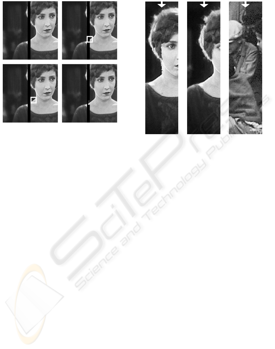
Figure 3: Principle of the exemplar-based inpainting
method. From left ro right: 1) scratched image to be in-
painted; 2) the pixel on the scratch edge with the highest
priority determines the position of the target patch (white);
3) the most similar patch to the target patch is found (white)
- the source patch; 4) the source patch is copied to the posi-
tion of the target patch.
Distance measure D used in our algorithm can be
formulated as follows:
D = βL
p
(T (ω) − S(ω)) + (1 − β)L
p
(TC − SC).
T , S, TC and SC denotes target patches, source
patches, target clue patches and source clue patches,
respectively. ω denotes the set of known pixels for a
particular patch. Parameters β =0.5 and p =5work
best in most cases.
A few results of our algorithm without transform-
ing the patches can be seen in Fig. 5. Results when
using rotation invariant patch matching are demon-
strated in the following sections.
3 ROTATION INVARIANT PATCH
MATCHING
In this section, we propose an efficient solution to ro-
tation invariant patch matching. The task is to take a
target and a source patch from the clue image, calcu-
late a few moments of each and answer the following
two questions:
• Is the source patch a good candidate for being a
match with the target patch after a proper transfor-
mation?
• If yes, what is the transformation? Since we model
it by rotation, what is the angle to rotate it by to be
able to find out if it is a match?
Figure 4: Images from Fig. 2, inpainted by the algorithm of
(Criminisi et al., 2004).
Moment rotation invariants are used in the next sec-
tions to answer both questions. Information about
moment invariants to rotation and about moment in-
variants by the method of normalization can be found
in (Flusser, 2000; Suk and Flusser, 2005).
3.1 Moment Invariants to Rotation
A few relevant results (see e.g. (Suk and Flusser,
2005)) are reproduced here. First, complex moments
and invariance are defined and the way to calculate
invariants to rotation is explained. Next, a few results
which are needed in this paper are emphasized.
A complex moment c
p,q
of order p + q of an image
f(x, y) is defined by the integral
c
pq
=
R
2
(x + iy)
p
(x − iy)
q
f(x, y)dxdy.
A moment invariant is a function of moments I such,
that the same function calculated from the moments
of the transformed image I
can be written as
I
=ΛI,
where Λ depends only on the transformation parame-
ters.
Invariants calculated by the method of moment nor-
malization are used here. After counterclockwise ro-
tation of an image by angle α, complex moments c
pq
are transformed into
c
pq
= e
i(p−q)α
c
pq
. (1)
Thus,
c
00
= m
00
EXEMPLAR-BASED INPAINTING WITH ROTATION INVARIANT PATCH MATCHING
117
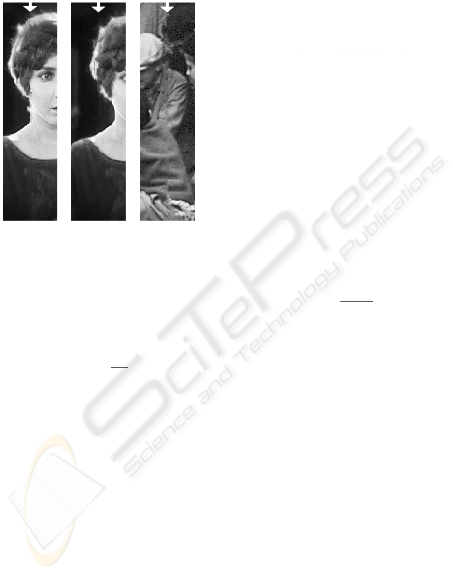
Figure 5: Images from Fig. 2, inpainted by our algorithm
using clue images, but with no invariance.
is one invariant (m
pq
is an ordinary moment).
Each patch, whose center of gravity is not in the
center of the patch, can be rotated by angle α so, that
the center of gravity is lying on the positive half of
the x-axis. Putting c
10
real and positive has the same
effect. To achieve this, eq. (1) gives the corresponding
rotation angle α
1
α
1
= − arctan
m
01
m
10
+ kπ
for k =0, 1, and condition
m
01
sin α
1
≤ m
10
cos α
1
.
Of course, division by zero has to be treated correctly.
After rotation by α
1
, patches are aligned to each
other and can be compared. The comparison can also
be done by calculating their moments m
pq
after ro-
tation (normalization). It is possible without rotating
the patches using only current moment values. The
moments are now independent of rotation (invariant)
and can be themselves used for comparison. Since the
normalized moment m
01
becomes zero, the first order
normalization gives one new invariant
m
10
=cosα
1
m
10
− sin α
1
m
01
.
If the center of gravity is too close to the center, i.e.
where
|c
10
| = m
2
10
+ m
2
01
(2)
is smaller than a threshold, the estimation of α
1
be-
comes unstable. Provided
|c
20
| =(m
20
− m
02
)
2
+4m
2
11
(3)
is large enough, normalization angle α
2
, based on the
second order moments can be calculated by the same
procedure. Putting c
20
real and positive gives
α
2
= −
1
2
arctan
2m
11
m
20
− m
02
+ k
π
2
for k =0, 1, 2, 3, and condition
2m
11
sin 2α
2
≤ (m
20
− m
02
)cos2α
2
.
3.2 Inpainting Strategy
Normalization and matching of the source patch to the
target patch works as follows: Both patches are multi-
plied by a circular mask to ensure rotation invariance.
Only moments up to the second order are used for ori-
entation estimation.
First, the orientation angle is estimated for the tar-
get patch and the normalized moments (invariants) are
calculated. For each source patch we try to reject it
based on the simplest features, before more complex
calculations have to be done.
Therefore, the distance of the mean intensity m
00
of the target and the source patch are compared at the
beginning. The calculation proceeds only if the dis-
tance is smaller than a threshold. All the thresholds
used in this paper are empirical. The relative distance
δ(a, b)=
|a − b|
|a| + |b|
is used for invariant comparison (with a small con-
stant in the denominator to prevent division by zero).
This is not an optimal measure, however it is only sup-
posed to be approximate to refuse the worst source
patch candidates.
After this step, first order moments are calculated.
If the value of (2) is larger than a threshold, α
1
is
estimated. α
1
is then used for normalization of the
first order moments. The relative distance of invari-
ants m
10
is compared and dissimilar patches are again
rejected. Moment m
11
is calculated, normalized and
used to detect if the patch should be reflected.
If the center of gravity should be too close to the
patch center, moments of the second order and m
21
(because of the test of reflection) are calculated. Mag-
nitude of the moment of inertia (3) is tested and the
procedure follows analogously.
Either α
1
or α
2
and information about reflection of
the patches are used to rotate and eventually reflect the
source patch. After it is aligned with the target patch,
they are compared based on our distance measure.
4 JUSTIFICATION FOR USING
MOMENT INVARIANTS
A few problems are connected with using moment in-
variants in this work. Some approximations might
VISAPP 2006 - IMAGE FORMATION AND PROCESSING
118
look too strong and they have to be justified. This
is the main goal of this section.
Firstly, both the target and the source patches are
square blocks of pixels. On the other hand, invariants
to rotation have to be applied to a circular patch to
make sense. A circular patch inscribed to the block
is used. Thus, it is assumed that pixels in the corners
of the block (not covered by the circular patch) are
approximate extrapolations of pixels in the middle of
the block. If the match for the inner part is good, the
same should then work for the corners.
Another problem is, that patches of small sizes are
typically used. In this paper, we use blocks of 5 × 5
pixels. The inscribed circle has to be roughly ap-
proximated. Bilinear interpolation is used here. In
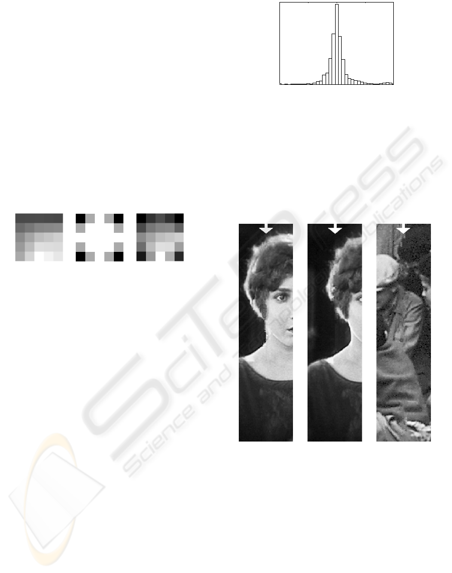
Fig. 6, an original square block and a circular mask
are shown, which are then multiplied to create a cir-
cular patch.
Figure 6: Demonstration of preparing circular patches.
From left to right: 1) square patch; 2) circular mask;
3) square patch multiplied by circular mask.
Estimation of the rotation angle is based on clue
images. However, the distance measure used in our
exemplar-based inpainting algorithm also takes into
account higher resolution image, which contains finer
texture. Our strategy is to use moments of low orders
which are not very sensitive to noise and to finer de-
tails.
The following experiment has been performed to
justify all the committed approximations. The an-
gle of rotation was first approximated using moment
invariants and clue images. Afterwards, the source
patches were rotated by a small step and for each sin-
gle orientation, the complete distance measure was
applied and optimal orientation was determined. The
histogram of differences α
dif
of these two values is
depicted in Fig. 7. The histogram reveals that our
method achieves approximately the same accuracy as
the method of (Drori et al., 2003), but it works much
more efficiently.
5 RESULTS
A few results are shown here to demonstrate the
strength of our inpainting algorithm, see Fig. 8.
Exemplar-based inpainting as briefly described in
Section 2, together with rotation invariant patch
matching is used here. It is obvious, that the results
−
180 −90 0 90 18
0
α
dif
[degrees]
Figure 7: Histogram of differences between angles esti-
mated by moment invariants and those obtained by testing
each orientation.
outperform those obtained by previous methods and
shown in Figs. 4 and 5. This fact can be attributed
to increased offer of available patches in a complex
non-textural image.
Figure 8: Images from Fig. 2, inpainted by the proposed
algorithm.
In movie restoration, it is also important to restore
noise and film grain to keep a natural look. Since the
patches are rotated before copying to the target patch
positions, they are also resampled. Bilinear interpo-
lation is used for this purpose. For a certain class
of noise and grain, there might be a visual distor-
tion. However, in the images used in this paper, we
have not observed any perceptually important noise
or grain degradation. If the results were bad, a second
attempt of exemplar-based inpainting re-graining flat
image areas could perhaps be used.
Incorporating rotation invariance does not signifi-
cantly slow down the inpainting algorithm. The nor-
EXEMPLAR-BASED INPAINTING WITH ROTATION INVARIANT PATCH MATCHING
119

Figure 9: Restoration of a film grain.
malized moments are used as a preliminary criterion
to refuse patches for the next comparison step, which
comprises resampling and distance transform calcula-
tion. The percentage of patches, allowed to be tried as
candidates for optimal source patches, depends on the
chosen thresholds. In our case it is 2% of all candidate
patches.
6 CONCLUSION
This paper uses, for the first time, moment invari-
ants for patch matching in exemplar-based image in-
painting. Difficulty with an incomplete target patch is
solved by using a clue image.
Justification for orientation estimation from lower
resolution images is discussed. Results of inpainting
with rotation invariance are demonstrated. They out-
perform the results of ordinary exemplar-based meth-
ods. Since the majority of patches are immediately
refused based on moment invariant values, the speed
of the algorithm is not significantly decreased.
Other invariance can be used. However, rotation is
probably the most appealing transformation. In im-
ages with curved edges it significantly improves the
results. Our main concern was testing applicability
of the method and not the final solution of scratch in-
painting in color sequences. Therefore, a simplified
problem of gray-value single frame inpainting is an-
alyzed. Extension of the method to color images and
usage of other patch transformations is the subject of
our next work.
ACKNOWLEDGEMENTS
This project is a part of the European IST FP6
project. The work was partially supported by the
Czech Ministry of Education under the project No.
1M6798555601 (Research Center DAR).
REFERENCES
Bertalmio, M., Sapiro, G., Caselles, V., and Ballester, C.
(2000). Image inpainting. In Akeley, K., editor, Sig-
graph 2000, Computer Graphics Proceedings, pages
417–424. ACM Press / ACM SIGGRAPH / Addison
Wesley Longman.
Bertalmio, M., Vese, L., Sapiro, G., and Osher, S. (2003).
Simultaneous structure and texture image inpainting.
In CVPR’03, IEEE Computer Society Conference on
Computer Vision and Pattern Recognition.
Chan, T. F., Kang, S. H., and Shen, J. (2002). Euler’s Elas-
tica and curvature-based inpainting. SIAM Journal of
Applied Mathematics, 63(2):564–592.
Chan, T. F. and Shen, J. (2001). Non-texture inpainting by
curvature-driven diffusions. Journal of Visual Com-
munication abd Image Representation, 12(4):436–
449.
Criminisi, A., P
´
erez, P., and Toyama, K. (2004). Region
filling and object removal by exemplar-based image
inpainting. IEEE Transactions on Image Processing,
13(9):1–13.
Drori, I., Cohen-Or, D., and Yeshurun, H. (2003).
Fragment-based image completion. ACM Transac-
tions on Graphics, 22(3):303–312.
Flusser, J. (2000). On the independence of rotation moment
invariants. Pattern Recognition, 33(9):1405–1410.
Joyeux, L., Boukir, S., and Besserer, B. (2002). Tracking
and map reconstruction of line scratches in degraded
motion pictures. Machine Vision and Applications,
13(3):119–128.
Suk, T. and Flusser, J. (2005). Image normalization by com-
plex moments. In et al., B.-T. J., editor, Proc. Int’l.
Conf. ACIVS’05, volume LNCS 3708, pages 100–107.
Springer.
Zhang, Y., Xiao, J., and Shah, M. (2004). Region comple-
tion in a single image. In Eurographics.
Zitov
´
a, B. and Flusser, J. (2003). Image registration meth-
ods: a survey. Image and Vision Computing, 21:977–
1000.
VISAPP 2006 - IMAGE FORMATION AND PROCESSING
120
