
ICR DETECTION IN FILLED FORM & FORM REMOVAL
Abhishek Agarwal, Pramod Kumar, Sorabh Kumar
Newgen Software Technologies Ltd.,
A-6 Satsang Vihar Marg, Qutab Institutional Area, New Delhi – 110067, India
Keywords: ICR Cells Detection, Handwritten Form Processing, Touching Characters, Line Removal, Component
Labeling, Form Removal, Character Preservation, Data Extraction, ICR/OCR/OMR Accuracy, Registration
Marks, Form Processing.
Abstract: This paper presents methods to enhance accuracy rates of ICR detection in structured form processing.
Forms are printed at different vendors using a variety of printers and at different settings. Every printer has
its own scaling algorithm, so the final printed forms though visibly similar to naked eyes, contains
considerable shift, expansion or shrinkage. This poses problems when data zones are close together as the
template reference points refer to the neighbouring identical zones, impeding data extraction accuracy.
Moreover, these transformational defects result in inaccurate form removal leaving behind line residues and
noise that further deteriorates the extraction accuracy. Our proposed algorithm works on filled forms
thereby eliminating the problem of difference between template and actual form. Template data can also be
provided as an input to our algorithm to increase speed and accuracy. The algorithm has been tested on a
variety of forms and the results have been very promising.
1 INTRODUCTION
World over, paper-based forms are a popular
medium for capturing data in a concise, organized
and consistent manner. However, for this data to be
used and subjected to further analysis, it has to be
converted into the electronic form. This can be done
either manually or through automatic form
processing (Liu et al., 1995). Manual data entry is
excessively time consuming and error prone.
Automatic form processing is fast and cost effective
but the results are rarely 100 percent accurate.
Automatic form processing solutions work best on
structured forms. Structured forms are static forms
that have precisely defined page layouts such that
templates can be built to geometrically identify and
extract needed data.
In traditional template-based approach (Mathur et
al., 1999) for structured form processing, the
template serves as the reference to specify the
location of the data fields to be captured from each
form. This approach uses vector distances of data
zones from some artefacts on the template, known as
registration marks, to locate the data fields on the
filled form. This approach works fine when the
quality of printed forms and scanning is very good.
In practical scenario, neither holds true. Forms are
printed from different printers at different points in
time and scanning is done in large batches at
different scan stations. This introduces multiple
distortions such as broken lines, skew, noise, black
borders, shrinkage/expansion, and shifting between
template and filled form. Some of these distortions
like noise, skew and black borders can be removed
using a number of available techniques (Pitas et al.,
1990) (Chih-Hong et al., 200) (Shi et al., 2003) (Le
et al, 1996). But in the presence of other distortions
like broken lines, shrinkage/expansion, and shifting,
reference vector distances of template cannot be
used to accurately locate data fields (Fig. 1).
Contents of a typical form are barcodes, OCR,
ICR and OMR data. OCR (Optical Character
Recognition) generally involves recognition of
machine printed characters. ICR (Intelligent
Character Recognition) is an extension of OCR,
which explicitly includes handwritten characters.
OMR (Optical Mark Recognition) entries are in the
form of a check mark, a cross or a scribble. Of these,
ICR data extraction is very challenging as ICR
engines work best on small and accurate zones.
These zones should not contain noise, line residuals
or static text like legends; otherwise it will hamper
the recognition rate. The most desirable situation is
providing the ICR engine with only the ICR
characters. Therefore, form removal becomes a very
271
Agarwal A., Kumar P. and Kumar S. (2006).
ICR DETECTION IN FILLED FORM & FORM REMOVAL.
In Proceedings of the First International Conference on Computer Vision Theory and Applications, pages 271-276
DOI: 10.5220/0001371202710276
Copyright
c
SciTePress
important step for ICR data extraction. Previous
systems relied on colored dropout boxes to remove
the form, but this needs the form to be printed in
color, which substantially increases the cost. If
printing and scanning quality is good and consistent,
template data can be used for form removal.
However, in presence of distortions as described
earlier, form removal is achieved by line detection
and removal from the filled form. ICR cells are
rectangular boxes present on the forms that serve as
guideline for the users to properly fill data in the
boxes. In most of the cases, characters written by
users are touching the bounding boxes or cutting
across two boxes. Line removal becomes a daunting
task in presence of boundary-touching characters. If
parts of character are erased, or if there are leftover
line residuals, the ICR engine may give erroneous
results.
(a)
(b)
(c)
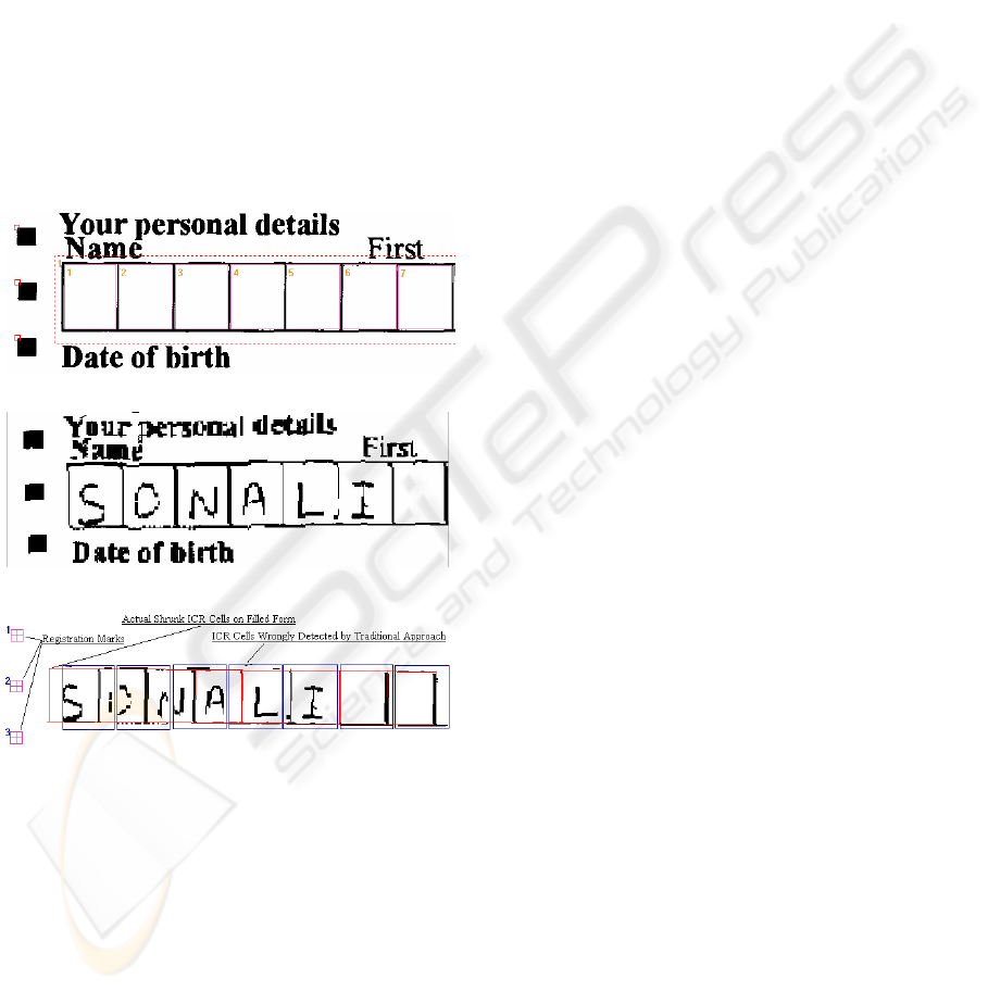
Figure 1: Traditional Template Based Approach (a)
Registration marks and ICR cells defined on Template (b)
Shrunk ICR cells present on the filled form (c) ICR cells
not formed out properly due to a slight shrinkage in the
filled form.
In this paper we present a novel algorithm to
overcome these two problems. ICR cell detection,
and line removal with character preservation is done
on filled forms to substantially increase the accuracy
rate. The algorithm has been tested and verified on
multitudes of form data, and the processing time
involved has been found to be considerably less.
The remainder of this paper is organized as
follows: Section 2 discusses the ICR cells detection
algorithm using an improved line detection
algorithm; Section 3 talks about accurate form
removal and ICR character preservation; and we
present some results and conclusion in Section 4.
2 ICR CELLS DETECTION
Locating ICR cells on filled forms having distortions
using traditional template-based approach (Mathur et
al., 1999) is unfeasible. ICR detection technique,
which was only applied on templates before is now
to be applied on filled forms also.
ICR cells are generally present as a collection of
multiple ICR cells. They can be described by some
common characteristics such as minimum width and
height, equidistant lines and L-shaped corners. ICR
cells are detected using equidistant, orthogonal
nodes formed by intersecting lines.
ICR detection is far more complex on filled
forms than on templates. Filled characters in ICR
cells give a false impression of ICR cell due to
detection of spurious lines in them. ICR characters
generally cut across cells or touch ICR cell
boundaries. This gives rise to the following three
problems:
1. Bounding lines of the ICR cell are not
detected at all.
2. During form removal, part of the character
gets removed.
3. Line residue is left.
Our algorithm is aimed at handling each of the
above-mentioned problems and achieving better
extraction accuracy. Line detection plays an
important role in ICR cells detection. A number of
line-detection algorithms have been proposed
(Illingworth et al, 1998) (Rosito Jung et al., 2004)
(Zheng et al., 2003) in the past but most of these
algorithms are either too slow for large sized
documents or do not necessarily support line
removal. After much research we selected line-
detection algorithm (Gattani et al., 2003). This line-
detection algorithm, apart from being fast and
accurate, can also be used for high precision line
removal. Using this algorithm, lines connected or
intersected by characters can also be easily detected
and removed. Lines are detected using a set of
specifications that are obtained in the form of user
input and is known as hyposet. The algorithm
VISAPP 2006 - IMAGE ANALYSIS
272
represents a line using accumulators, collections and
buckets. Each line is formed by small segments of
continuous black-pixel runs along the same scan
line. These segments are stored in the accumulators
and the collection of such segments that form a line
is known as a bucket. A bucket holds information
about the whole of the line such as the average
thickness, skew and orientation. Using these
accumulators, collections and buckets we generate
an exact bitmap of the line that can be used for
further analysis while performing line removal.
Some changes were made to the line detection
algorithm (Gattani et al., 2003) to suit our needs.
These changes are aimed at better line
detection/removal and character preservation after
line removal. A new specification is added to the
hyposet, known as minimum segment length, as it
was observed that the ‘minimum line length’ was
insufficient for accurate detection of lines. Segment
length is used to detect even jagged lines in the form
(Fig. 2). The algorithm is also modified to preserve
characters (Yoo et al., 1995) that are cut by lines
while removing lines. Previously, when these
detected lines were removed using (Gattani et al.,
2003), the characters were broken and the ICR
engine’s accuracy was reduced. To overcome this,
smearing of the line-surrounding neighbourhood is
done with a threshold equal to the thickness of the
line. Horizontal smearing is done for vertical line as
is vertical smearing for horizontal lines. This is
followed by OR-ing this with the original image.
This achieves character preservation (Fig. 3).
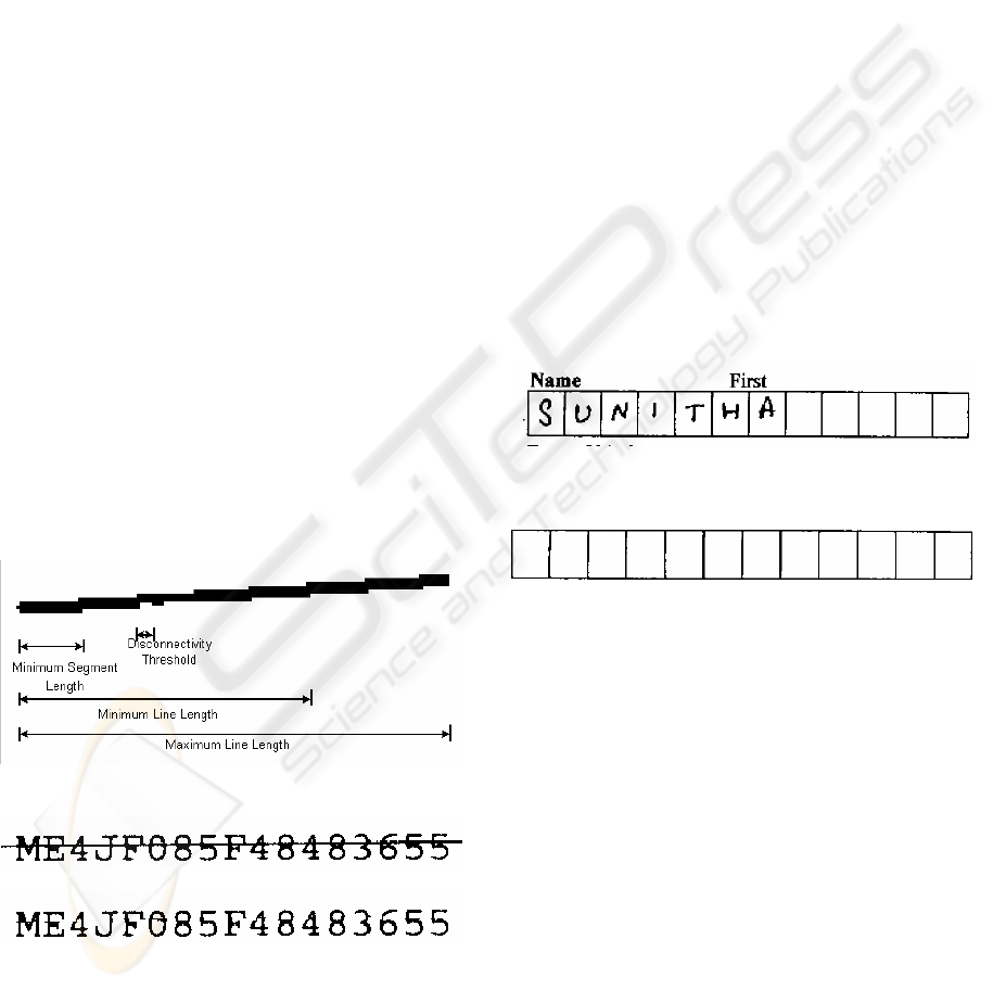
Figure 2: Minimum segment length in line specifications.
(a)
(b)
Figure 3: (a) Characters cut by lines (b) Characters get
preserved after line removal using improved line removal
algorithm.
Template information, if provided, can improve
the performance and accuracy of the algorithm.
Template information will generally be in terms of
number of cells, coordinates, minimum width and
height of the ICR cells, average thickness of lines,
etc.
2.1 Algorithm
As the first step, we smear the image, both
horizontally and vertically, by a resolution-
dependent threshold so as to join the broken
components. An eight-neighbour connected
component-labeling algorithm (Dillencourt et al.,
1992) is then used to get the connected components.
We create a bitmap of each component for further
processing (Fig. 4). Further analysis is done on the
component bitmap as doing so helps us eliminate all
the character components that lie inside the ICR
cells and are not touching the ICR cell boundaries.
This helps in eliminating most of the spurious lines
detected in the characters that might confuse or
complicate our ICR cell-detection analysis.
(a)
(b)
Figure 4: (a) ICR cells on the filled form to be detected (b)
Component Bitmap of ICR cells obtained by connected
component labelling.
Candidate components for ICR cells are defined
as those components that have dimensions greater
than the minimum ICR cell width and height. For
each such candidate component, we detect lines on
that component’s bitmap using the improved line
detection algorithm (Fig. 8(c)).
Once we have all the lines information of the
component, we assume that the component is an ICR
cell, and filter lines based on the characteristics of
ICR cells. First, we estimate the average width and
height of the ICR cells using the equidistant lines
and equidistant orthogonal nodes formed by them.
Average width and height of ICR cells obtained
from template can be directly used, if available. In
ICR cells, the valid boundary lines must all lie at a
ICR DETECTION IN FILLED FORM & FORM REMOVAL
273
distance of average width from their predecessor.
Using this fact and the average width and height, we
determine the valid ICR cell lines (Fig. 8(d)). All
other invalid lines are rejected at this stage. Once we
have the valid lines and the nodes formed by them,
we verify whether the lines and the nodes form a
valid ICR cell. To verify the ICR cell, the type and
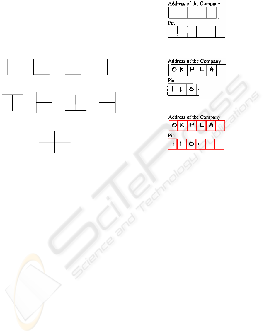
orientation of each node is determined (Fig. 5).
L Junctions (South-East, North-East, North-West, South-West)
T Junctions (North, West, South, East)
Cross ( + ) Junction
Figure 5: Different types and orientations of nodes.
Based on type, orientation of each node and distance
between successive nodes, ICR cells are determined.
In case some of the ICR cells are distorted and
are not detected, we estimate them using the
template information and Tied Strings probabilistic
estimation approach (Mathur et al., 1999). To
estimate the ICR cells, first we determine the scaling
factor (SF) between template and filled form. SF is
the ratio of average width of ICR cells on template
to that on the filled form. SF is calculated by
n m
SF = ( ∑W
t
i
/ n ) / ( ∑W
f
j
/ m )
i=1 j=1
where
n is the number of ICR cells detected on
template.
m is number of ICR cells detected on filled
form. (m < n and n-m cells are to be estimated).
W
t
i
is width of i
th
ICR cell of template.
W
f
j
is width of j
th
ICR cell of filled form
Each detected ICR cell on filled form is mapped
onto the corresponding ICR cell on template using
SF and vector distances to determine the
corresponding unmapped cells of the filled form
(Fig. 6).
(a)
(b)
(c)
Figure 6: (a) ICR cells present on the template (b) Some
of the ICR cells not present on the filled form (c) ICR cells
on the form are estimated and properly formed out using
template information.
3 FORM REMOVAL
After detection of ICR cells, the next task is form
removal. Form removal is the task to properly
remove ICR boundary lines (Yoo et al., 1995) so
that final image contains only ICR characters for
better ICR extraction. We do this by traversing the
accumulators given by improved line removal
algorithm. However, the algorithm may still remove
some parts of ICR characters that are touching ICR
cell boundaries. Also, the line removal algorithm
may leave some line residues.
To prevent erosion of touching characters, we
use the information of valid ICR lines. First of all,
we try to detect those lines that are attached to
characters. To do so we remove the valid ICR lines
from the component bitmap using accumulators,
collections and buckets. On this updated component
bitmap, we do component labeling to find the
connected components. These components are the
part of the characters attached to the ICR cell
boundary (Fig. 8(e)). We scan the original and
updated component bitmap one row at a time to
VISAPP 2006 - IMAGE ANALYSIS
274
select the lines that are attached to the ICR character
components, the direction of attachment (i.e. left,
right or both for vertical lines or top, bottom or both
for horizontal lines) and projection profile of each
line on both directions using the accumulators.
(a)
(b)
(c)
Figure 7: (a) Filled ICR cells (b) Form Removal after ICR
detection without character preservation (c) Form
Removal after ICR detection with character preservation.
Note that no line residue is left in both the cases
.
We now have two disjoint sets C and U of lines,
one having lines that are connected to the characters
(C) and other having the ones that are Unconnected
(U). We have to reduce the thickness of each line of
set C so that the part of the character attached to it is
not removed. To do so, we first determine the
maximum thickness of lines of set U. Then we
update the accumulators and corresponding bucket
of each line of set C from the direction opposite to
the direction of attachment. In case the direction of
attachment is both, we have to preserve the character
present on the critical side. Critical side is decided
on the basis of the standard deviation of projection
profile for both directions. The side having more
standard deviation is always the critical one (Fig. 7).
Finally, we remove small line residues by
applying eight-neighbour connected component
labeling and removing very small, noise-like
components that are close to the ICR boundaries
(Fig. 8(f), 8(g)).
4 RESULTS AND CONCLUSION
The intermediary results and the flow of the
algorithm are summarized below through pictorial
depiction.
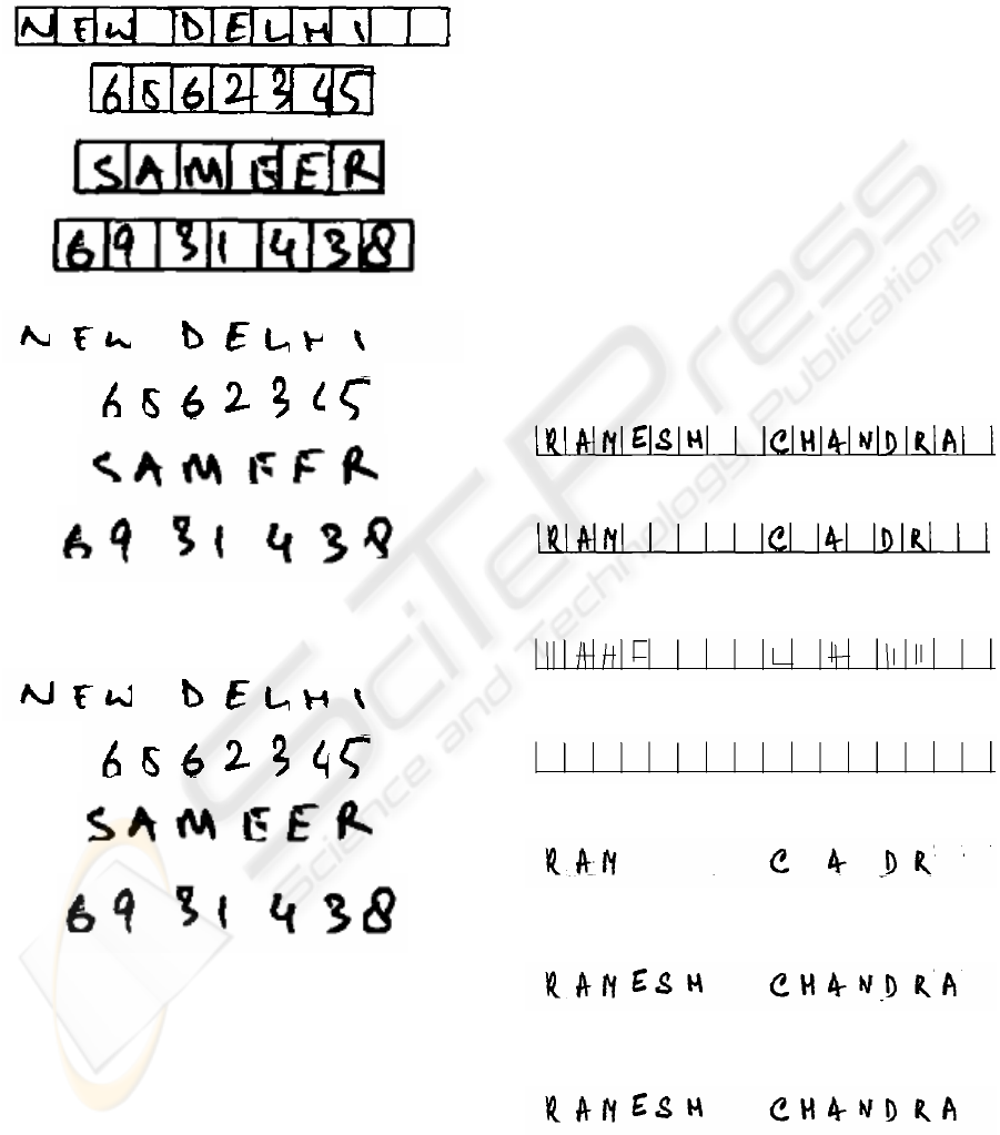
(a) ICR cells on a filled form
(b) Component Bitmap of ICR cells obtained by
connected component labeling
(c) Lines detected on component bitmap
(d) Filtered lines on component bitmap
(e) Filtered lines removed from component bitmap to
preserve characters
(f) Filtered lines finally removed from original image
after preserving characters
(g) Bitmap after form removal. Line residues removed
Figure: 8 Results during intermediate stages in our
algorithm.
ICR DETECTION IN FILLED FORM & FORM REMOVAL
275

We tested our algorithm on a mix of several
educational and business forms containing different
types of ICR cells used in different layouts. Our
batch consisted of 918 different images, which were
further divided into two separate sets based on
whether template information is present. We used
Newgen OmniExtract Form Processing Engine to
run our tests. Caere engine was used for ICR.
On a batch size of 500 images, structured form
processing approach was followed that used
template information. We tested using both the
approaches; the traditional vector distance mapping
and our proposed approach. The image dataset had a
collection of images with skew (+ 3 degrees), shift
and shrinkage. Out of the 500 images, 10% of the set
had images that contained broken or missing cells
and required estimation. We recorded a 77%
improvement in data extraction using the proposed
algorithm. We calculated the number of correctly
extracted ICR cells for both the approaches to get a
measure of the improvement in data extraction. The
improvement was due to the accurate ICR cell
detection and estimation and better form removal
(Fig. 8).
On a batch size of 418 images, we followed the
unstructured form processing approach by passing
the whole image to our engine as input without any
template information. The results were again very
promising with a total data extraction accuracy
percentage of 97.9%.
The experiment results show that our approach,
even when not using the template information,
brings in highly accurate data extraction results
when compared to the traditional form processing
approach. The result also underscores the fact that
the proposed solution can be applied to unstructured
form processing where ICR cells can be detected
and used for document understanding, classification,
and segmentation.
REFERENCES
Liu J., Ding X., Wu Y. 1995. Description and recognition
of form and automated form data entry. In ICDAR'95,
Third International Conference on Document Analysis
and Recognition - Volume 2,pp. 579-582.
Mathur, A., Gur, N.H., 1999. High Performance Form
Analysis and Data Extraction. In ICDAR’99, Fifth
International Conference on Document Analysis and
Recognition.
Pitas,I. and Venetsanopoulos, A. N. , 1990. Nonlinear
DigitalFilters. Boston: Kluwer Academic, 1990.
Chih-Hong, K., Hon-Son, D., 2005. Skew Detection of
Document Images Using Line Structural Information,
In ICITA'05, Third International Conference on
Information Technology and Applications Volume 1.
Shi, Z., Govindaraju, V., 2003. Skew Detection for
Complex Document Images Using Fuzzy Runlength.
In ICDAR'03, Seventh International Conference on
Document Analysis and Recognition - Volume 2, 715-
719.
Le D. X., Thoma G.R., Wechsler H.1996. Automated
border detection and adaptive segmentation for binary
document images. In Proceedings of ICPR ’96.
Illingworth, J., Kittler J., H.1998. A survey of the Hough
transform. CVGIP, Vol. 44.87-116, 1998.
Rosito Jung C., Schramm R. 2004. Rectangle detection
based on a windowed Hough transform. In
SIBGRAPI'04, Computer Graphics and Image
Processing, XVII Brazilian Symposium on , 113-120.
Zheng Y., Li H., Doermann D. 2003. Background line
detection with a stochastic model. In 2003 Conference
on Computer Vision and Pattern Recognition
Workshop - Volume 3.
Gattani, A., Mukerji, M. and Gur, H., 2003. A Fast
Multifunctional Approach for Document Image
Analysis. In Proceedings of the Seventh ICDAR, 2003,
1178-1182.
Yoo J., Kim M., Yong Han S. 1995. Line Removal and
restoration of Handwritten Characters on the Form
Documents. In ICDAR'97, Fourth International
Conference Document Analysis and Recognition ,
128-131.
Dillencourt, M.B., Samet,H., and Tammininen,M., 1992.
General approach to Connected-Component Labeling
for Arbitrary Image Representations, In J.ACM Vol
39, No.2, 1992, pp. 253-280.
VISAPP 2006 - IMAGE ANALYSIS
276
