
3D RECONSTRUCTION METHODS, A SURVEY
Julius Butime
CEIT and TECNUN(University of Navarra), Manuel Lardizabal 15,20018 San Sebastian, Spain
Dr. Iñigo Gutierrez
TECNUN(University of Navarra), Manuel Lardizabal 15,20018 San Sebastian, Spain
Luis Galo Corzo
CEIT and TECNUN(University of Navarra), Manuel Lardizabal 15,20018 San Sebastian, Spain
Carlos Flores Espronceda
CEIT and TECNUN(University of Navarra), Manuel Lardizabal 15,20018 San Sebastian, Spain
Keywords: 3D Reconstruction, Triangulation, Holography, Stereoscopy, Conoscopic holography.
Abstract: 3D reconstruction technologies have evolved over the years. In this paper we try to highlight the evolution
of the scanning technologies. The idea of a survey came up with our decision to look at 3D reconstruction
methods. Little has been written about the methods in general, yet many developments have taken place in
this area. This survey will prove useful for those intending to embark on research in 3D reconstruction
technologies or are considering acquiring a 3D scanner. The survey takes a look at the major reconstruction
methods, which are; Laser triangulation, Stereoscopy, Conoscopic holography and Moiré Interferometry. A
review of the major producers of scanning technology for 3D reconstruction is also carried out.
1 INTRODUCTION
3D reconstruction methods are classified into
passive and active. Passive methods do not involve
interaction with the object, whereas active methods
use contact or a projection of some form of energy
onto the object. Our main in this paper is given to
the active methods that use the projection of a form
of energy onto the objects, light in our case. Active
methods involving contact with the object are being
phased out due to their slow reconstruction process
and the need for less contact with the object to avoid
them getting damaged (Curless, B). In this paper,
our main focus will be on the optical non contact
methods that offer faster reconstructions since they
are commonly applied in the manufacturing
industry. In the field, the main method used to
realise reconstructions is optical laser triangulation.
Section two deals with the various methods of
3D reconstruction, whereas section 3 analyses the
3D scanners on the market. We make comparisons
based on the technical specifications provided by the
manufacturers. The last section contains a summary
of all the results from the survey. Given the
importance of faster prototyping in modern industry,
one can easily appreciate the amount of time and
money that is saved when 3D scanning methods are
used. At present many of the leading manufacturing
industries have incorporated in their production lines
systems for 3D scanning. This has helped increase
their productivity and save on the time it takes for a
product to be released on the market. On the whole,
the benefit of these scanning systems is the
improved product quality, time to market and the
reduction of the overall production cost.
457
Butime J., Gutierrez D., Galo Corzo L. and Flores Espronceda C. (2006).
3D RECONSTRUCTION METHODS, A SURVEY.
In Proceedings of the First International Conference on Computer Vision Theory and Applications, pages 457-463
DOI: 10.5220/0001369704570463
Copyright
c
SciTePress
2 3D RECONSTRUCTION
METHODS
As has been mentioned in the previous section, here
we take a look at the broad range of 3D
reconstruction methods.
2.1 Laser triangulation
Laser triangulation is the most common method used
in commercial 3D scanners. The principle of
operation of Laser triangulation involves the
projection of a ray of light over an object in the form
of a point. If the object is to be captured by a
camera, only a bright spot should be detected.
Therefore knowing with precision the relative angle
of projection with respect to the base line, it is
possible to determine the position of the point in
space. The variants of laser triangulation are based
on the many ways of projecting and detecting the
light rays. In the case of a point source, the whole
scene has to be scanned both vertically and
horizontally to obtain the depth. If instead of
projecting a point, a line is projected, the depth of all
the points on the line can be obtained at the same
time. This explains why techniques based on the
projection of a line are much faster than the
projection of a single point. One may use various
methods to project the light onto the scene, each one
with its merits and demerits. The precision, the
presence of blind spots, where triangulation is made
impossible, and the speed of scanning the scene are
the principle factors to be taken into account when
choosing the kind of technique.
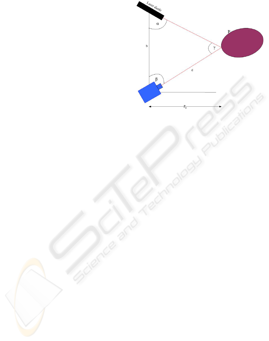
Principle of operation
Consider the figure shown below. A ray of light
originating from a laser diode is focussed on an
object at point P. The ray is observed using a camera
placed at an angle to the object. The separation of
the camera from the laser diode is known. Using
triangulation theory the distance of the object in the
z axis is recorded.
The laser diode is located on the x-axis, at a known
distance from the camera b. Assuming P is in the x,z
plane, the distance and projection angle of the laser
diode are established before hand.
Figure 1: Triangulation setup.
Our next main problem is to solve for the distance
Z
p
from the object. Using similar triangles, the sine
rule is applied to the setup. A derivation of the
distance Zp is obtained can be found in the reference
(Klaus D. )
2.2 Stereoscopy
Stereo vision refers to the ability to deduce
information on the 3D structure and distance of a
scene from two or more images of taken from
different viewpoints. The name stereoscopy was
given to this method by Sir Charles Wheatstone
(Wheatstone, C). Stereo vision involves two
processes: the binocular fusion observed by the two
eyes, and the reconstruction of the three-dimensional
image. The pre-image of the matching points can be
found at the intersection of the rays passing through
these points and the associated pupil centres or
pinholes. In a stereo system, we look for
correspondences existent between the two images
i.e. which parts in both images are projections of the
same scene. Having obtained the correspondences,
the 3D structure is determined using epipolar
geometry. By estimating the disparity between two
images, the height of each point is evaluated. The
robustness of the process is ensured by modeling
and taking into account the geometric nature of the
elements observed.
VISAPP 2006 - MOTION, TRACKING AND STEREO VISION
458
Principle of Stereoscopy
Camera1
Camera2
Object as seen in
camera 2
Object as seen i
n
camera 1
Object
Figure 2: Stereo setup.
As was mentioned above, stereo vision involves the
matching of points observed in two images captured
by two cameras. This matching is done using
epipolar geometry. Epipolar geometry involves the
the observation of a single point in two images and
relating the coordinates in each of the images.
(Owen, R)
2.3 Holography
Holography is a technique by which a wave front
can be recorded and subsequently reconstructed in
the absence of the original wave front. The method
was proposed and demonstrated by Gabor in 1948
long before the laser came into existence.
Observation of this reconstructed wave front gives
exactly the same physical effect as the observation
of the original wave front. On illuminating the scene
after removing the object, a three dimensional image
is observed as though the object was still present.
Leith and Upatnieks were the pioneers in applying
holography to three dimensional imagery way back
in 1964. This depended largely on the availability of
the HeNe laser, which had an excellent temporal and
spatial coherence (Goodman, C).
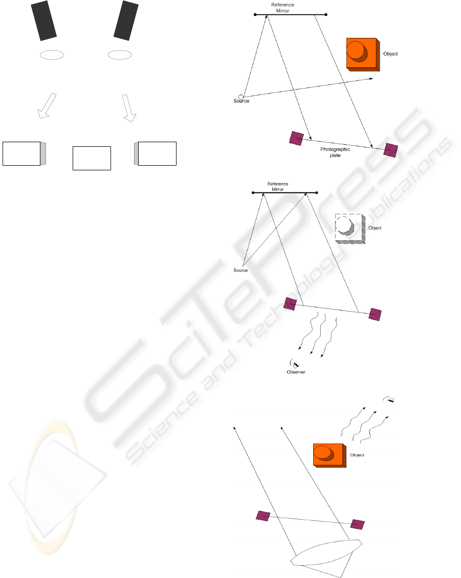
Figure 3 shows the geometry used for recording
holograms of a three dimensional scene.
Figure 3: a) Capture of the hologram.
Figure 3: b) Observing the virtual image
Figure 3c) Observing the real image.
Coherent light illuminates the scene of interest. A
portion of the light is reflected from a mirror onto
3D RECONSTRUCTION METHODS, A SURVEY
459
the photographic plate. This light reflected serves to
form the 3D hologram of the object on the
photographic plate by interfering with the light rays
from the object. The reconstruction of the scene is
carried out as follows; there are two possible
configurations, one giving the virtual image and the
other giving the real image.
To obtain the virtual image, the object is
removed from the setup in figure 3a) and the
photographic plate is illuminated by the same light
source that was used while capturing. A virtual
image of the object results as can be seen in Figure
3b). Lastly, if the photographic plate is illuminated
from the opposite side i.e. different from the one that
was used to capture the hologram, a real image of
the object can be observed. These images both
virtual and real are used in the reconstruction of
objects in three dimensions (Goodman, C).
2.4 Conoscopic holography
Conoscopic holography is a relatively new non
contact method used to reconstruct objects in three
dimensions. It was discovered by Gabriel Sirat and
Demetri Psaltis in 1985 as a modification to
coherent holography for three dimensional data
recording and imaging (Sirat, G., Psaltis, D., 1985).
It is based on the propagation of light in anisotropic
crystals. The property that enables the crystal to split
the light rays into ordinary and extra ordinary rays is
referred to as birefringence.
Birefringence is a property of certain crystals,
which when a ray of light travels through their
different optical axes, travels at different velocities.
This behaviour is characteristic of anisotropic
crystals given that they posses varying indices of
refraction caused by the nature of the crystal lattice.
Having split the light ray into an extraordinary
and ordinary beam they are made to interfere thus
and give measurements of high precision.
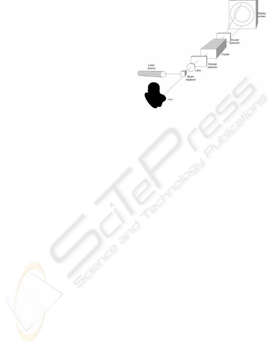
Principle of operation
Consider a point source of light originating from
an opaque object as is shown in figure 4. The
conoscope comprises of the birefringent crystal,
usually made of calcite, sandwiched between two
circular polarizers. The recording of the holograms
is done on a CCD matrix. This ray travels from the
object towards the uniaxial crystal after penetrating
the first circular polarizer. On entering the uniaxial
crystal, the ray is divided in two, the ordinary and
extraordinary.
Figure 4: Conoscopic holography setup.
These rays are out of phase with each other and
travel at different velocities within the crystal. At the
other end of the crystal the ordinary and
extraordinary rays are made to interfere after going
through the second circular polarizer, which among
other things returns both rays to the same phase. The
resulting rays are made to interfere leading to either
constructive or destructive interference. The
resulting interference patterns are the conoscopic
holograms and these contain the distance
information that we are interested in. For a more
detailed explanation of the principle with a
mathematical foundation refer to (Sirat, G., 1992).
2.5 Moiré Interferometry
The term Moiré refers to an irregular wavy finish
usually produced on a fabric by pressing between
engraved rollers. In optics, it refers to a beat pattern
produced between two gratings of approximately
equal spacing. Moiré is a technique to study strains
and deformations of structural elements with very
high accuracy. It requires a highly stable
environment and has mainly been a laboratory tool.
Recently attempts have been made to develop a 3D
scanner that uses moiré interferometry (Dubowsky,
S). The method can be grouped under two major
classifications that depend on the optical
arrangement used: projection and shadow.
Projection moiré involves the projection of a
matching pair of gratings. The projection grating is
placed in front of the light source and the reference
grating is placed in front of the camera. The
projected beam light is amplitude modulated with
the pitch of the grating. When the beam falls on the
surface of the object, the phase of the spatial carrier
is modulated by the shape of the object surface. The
VISAPP 2006 - MOTION, TRACKING AND STEREO VISION
460

Table 1: 3D Scanners’ parameters.
Company Type of
scanner
Scanning
technique
Working
range
(mm)
Speed
(points/sec
ond)
Accuracy
(mm)
Type of
surface
Konica
Minolta
Vivid 700
Triangulati
on
600-25,000 n/a 0.11 Diffuse
Optimet Conoline Conoscopic
holography
45 4,000 0.047
Diffuse to
shiny
3D
Scanners
MMZ
Laser
Triangulati
on
50-150 n/a 0.1 Diffuse
Opton
Mini Moire
scanner
Moiré
interferome
try
15 150,000 0.025 Diffuse to
shiny
Roland
DGA
Pix30
Laser
Triangulati
on
0.2-406 n/a n/a Diffuse
3rdTech
Deltasphere
3000
Time of
Flight
300-
12,000
25,000 n/a Diffuse
IQ
instruments
CMMaster
Moiré
interferome
try
n/a 80,000 < 0.025 Diffuse to
Shiny
Nub 3d SIDIO Laser
Triangulati
on
700 0.08
Diffuse
Coherix Shapix Phase
shifting
interferome
try
450 17,476 <0.02 Diffuse to
shiny
Geodetic
systems
Vstars(E4X
)
Stereoscop
y
n/a n/a 0.008 Diffuse
Faro
Technologi
es
Faro laser
scanner
Interferome
try
120,000 120,000 0.025 Diffuse to
shiny
Brueckman
n
OptoTOP-
HE
Structured
light
25-400 1,555,555 0.045-0.45
Diffuse
Perceptron Scanworks Laser
Triangulati
on
23-71 23,040 0.035
Diffuse
reference grating is phase shifted against the
projection grating.
Shadow moiré involves positioning a grating
close to an object and observing its shadow on the
object through the same grating. Moiré is considered
a very good method for 3D reconstructions because
it amplifies small errors, thus enabling their
detection. It requires less computer time, and so has
a great potential for rapid online registration and
inspection. The parameters of a moiré can easily be
changed. Moiré however has not been fully
exploited owing to the difficulties encountered in
designing and adjusting a system based on it.
In moiré interferometry, light is projected onto
an object’s surface through two equally spaced
fringes. The resulting patterns are viewed at an angle
different from that at which the fringes are projected.
The contour interval depends on the spacing of the
fringes projected on the surface and the projection
viewing angle. A detailed mathematical analysis of
the formation of the moiré fringes may be found in
(Creath, K., Wyant, J).
3D RECONSTRUCTION METHODS, A SURVEY
461

3 COMPARISON OF 3D
SCANNERS ON THE MARKET
The manufacturers of 3D scanning equipment can be
grouped in three categories; those that provide the
hardware, those that write the software and those
that implement both systems. We looked at the
leading manufactures of 3D scanners and this
enabled us to make a comparison of their various
products. Given that these use different technologies
these results are not easily compared since we have
to identify uniform parameters for comparison in
each of the methods. Owing to the variations in
software available on the market, the survey has
been limited to the comparison of the hardware and
its performance. Definitely their performance
depends greatly on the software, but that will be
dealt with in another article.
The providers of scanners that we have been able
to identify, that use each of the various technologies
for 3D reconstruction are diverse. A look is taken at
those who provide the datasheets on their products.
Using these, a comparison of similar parameters is
carried out to come up with unbiased conclusions.
The scanners are commercial implying that we
have had to rely on the information provided by their
manufacturers, as it is close to impossible to have all
scanners in the university laboratory considering
their high cost. The parameters taken into
consideration were; the operating range, accuracy,
speed of capture, and the types of surfaces. Each
scanner will be compared with a series of cameras in
the same range. This will be followed by a
comparison of with the results from other scanning
techniques. The survey looked at products from the
following companies: 3D Scanners (MMZ), Konica
Minolta (VIVID 700), Optimet technologies
(Conoline), Opton formerly EOIS (Moiré scanners),
Roland (Pix 30) among others.
Table 1. shows these parameters in several
commercial scanners. Judging from the results
presented, several observations about the various
technologies can be made. Laser triangulation is the
commonest method used in 3D scanners, as seen in
the table most scanners use triangulation. The
reasons that are put forward for its popularity are;
it’s easy setup, its low cost as compared to other
methods, its speed which enables real time scans and
reconstructions on the production line. Laser
triangulation is limited when very high precision and
accuracy are required. It is also marred by speckle
and inability to scan reflective surfaces.
Stereo is passive and does not emit any radio or
light energy. Recording on site can be done very fast
and as such it can be used on-line. However, the
matching of the points in the two images captured by
the cameras in stereo is tedious. Whereas they can
adjust for component size, stereo cannot easily
accommodate free form surfaces. In addition, the
requirement for one of the two cameras to be fixed
at a specific angle restricts the inspection region and
presents difficulty in inspecting the entire
component. The scene has to be rigid to begin
reconstruction which makes it difficult for on-line
implementation.
Moiré is considered a very good method for 3D
reconstructions because it amplifies small errors,
thus enabling their detection. It requires less
computer time than other methods like laser
triangulation during capture, once it has been
properly setup, and so has a great potential for rapid
on-line registration and inspection. The parameters
of a moiré can easily be changed. Moiré limitations
can be cited in the difficulty in its design and in
adjusting the setup to capture data. Its very high
precision makes the acquisition costs extremely
prohibitive (Dubowsky , S).
Holography performs much better than laser
triangulation when it comes to precision and
accuracy. Readings of up to several microns can be
taken. However it is limited as far as speed is
concerned. A lot of precaution has to be taken when
recording the holograms since lengthy exposure
requires a high level of stability in order to obtain
good results in the processing. The range for
recording the holograms also has to be well chosen
in order to get a good reconstruction. Holography
has not been fully taken on in industry inspite of
being very accurate, given the complication in
adjustments that have to be made while taking
readings.
Conoscopic holography being a modification to
holography sorts out the speed problem. It features a
high precision in its readings and reconstructions of
up to 47 microns using an objective of focal length
100mm. The accuracy and range depend on the
objectives used on the conoline. Conoscopic
holography has clearly enabled holography to be
applied to the manufacturing industry. Of the
benefits we are able to note using the conoline is the
ability to measure several surfaces and reach an
angle of incidence up to 85º, which not many
methods are capable of doing. Conoscopic
holography could still benefit from an increase in its
speed of capture in order to be adapted to more real
time applications. (Optimet)
VISAPP 2006 - MOTION, TRACKING AND STEREO VISION
462

4 CONCLUSIONS
Having looked at the various methods of 3D
reconstruction, we hereby are able to reach a
decision on which technology to be used in our 3D
scanner. The pros and cons of each and every
method have been expounded, in order to serve as an
aid to all those wishing to implement scanning
processes for both experimental and industrial
purposes.
REFERENCES
Harding, K., 1995. 3D Machine Vision as a shop Floor
Metrology tool, General Electric..
Forsyth, D., Ponce, J., Computer vision: A modern
approach,
Jones, R., Wykes, C., Holographic and Speckle
interferometry,
Besl, P., Active Optical Range Imaging Sensors,
Goodman, C., 1996. Introduction to Fourier Optics,
McGraw Hill
Russ, J., The image processing handbook.
Creath, K., Wyant, J., Holographic and Moire techniques
http://www.optics.arizona.edu/jcwyant/Optics513/Lab/Mo
ireTechniquesLab12.pdf
Gungor, S., Moire Interferometry
http://deme.open.ac.uk/moire.html
Optimet (Optical Metrology )
http://www.optimet.com
The Computer Vision Homepage
http://www.cs.cmu.edu/afs/cs/project/cil/ftp/html/visio
n.html
Wheatstone, C., On some remarkable, hitherto unobserved
phenomena of Binocular Vision, Philosophical
transactions of the Royal Society of London, Vol. 128,
pp. 371 - 394.
Curless, B., 1997, New Methods for Surface
Reconstruction from Range Images, PhD Thesis
Sirat, G., D. Psaltis., 1985, "Conoscopic Holography,"
Opt. Lett. 10, 4-6 ().
Sirat, G., 1992 "Conoscopic holography. I:emsp ]Basic
principles and physical basis," J. Opt. Soc. Am. A 9,
70-
Minolta. Data sheet for the Vivid 700 camera.
Optimet technologies. Datasheet for the Conoline.
Goodman, J., 1996. Introduction to Fourier Optics,
McGrawHill.
Klaus DT., 3D Computer vision. 3 depth from
Triangulation (Active Vision)
Creath, K., Wyant, JC., Moire Fringe and Projection
techniques
Dubowsky, S., Holly, K., Murray, A., Wander, J.,
Design optimization of moiré interferometers for rapid
3-D manufacturing inspection. Massachusetts Institute
of Technology, Cambridge MA.
Owen, R., 1997, Computer Vision Lecture notes, Epipolar
Geometry
http://homepages.inf.ed.ac.uk/rbf/CVonline/LOCAL_COP
IES/OWENS/LECT10/lect10.html
3D RECONSTRUCTION METHODS, A SURVEY
463
