
COMPUTER VISION BASED INTERFACES FOR INTERACTIVE
SIMULATIONS
Ben Ward, Anthony Dick
School of Computer Science, University of Adelaide, Adelaide, SA 5005, Australia
Keywords: Real-time Vision, 3D Motion and Tracking, Human-Computer Interaction.
Abstract: 3D environments are commonplace in applications for simulation, gaming and design. However, interaction
with these environments has traditionally been limited by the use of 2D interface devices. This paper
explores the use of computer vision to capture the 3D motion of a handheld object by tracking known
features. Captured motion is translated into control of an object onscreen, allowing 3D interaction with a
rendered environment. Objects are tracked in real-time in video from a single webcam. The technique is
demonstrated using two real-time interactive applications.
1 INTRODUCTION
With the growing power of personal computers, 3D
environments have become a common feature of
applications for gaming, simulation, art, and design.
However, these 3D applications often require
complex combinations of keys, mouse buttons and
mouse motion to map 2D input to 3D motion. The
interface described in this paper bypasses traditional
controls, enabling 3D motion to be captured visually
and used to directly drive interaction in 3D
environments.
This system was designed for use as a general-
purpose 3D interface in a home or office
environment. As such, it would have to meet a
number of challenging requirements:
– No use of expensive specialized hardware
– Run in real time on a current desktop PC
– Track in 3D with sufficient accuracy for
intuitive control
– Cope with fast motion
– Cope with variation in lighting conditions
– Cope with background clutter
To our knowledge, no existing system (including
this one) fulfils all of these criteria. However, we
adopt and adapt several techniques from computer
vision and graphics to address these issues in a novel
way.
Significant effort has also been invested in
developing convincing demonstrations of how these
interfaces can be applied to games and other
applications involving physical simulation, where
the interface enables direct interaction between real
and simulated objects. The interfaces are general-
purpose enough that they could be adapted to other
applications, such as the manipulation of objects for
3D design and visualisation.
An overview of the system is as follows. Colour-
based tracking is used to locate and follow the 2D
motion of a simple handheld object by identifying
one or more features, as described in section 2. That
motion is then refined and transformed into 3D
motion based on knowledge of the camera and the
object, as described in sections 3 and 4. Five degree
of freedom motion is enabled by tracking a pair of
features. The recovered 3D motion is used to interact
with a rendered environment, as described in
sections 5 and 6.
1.1 Related work
The field of computer vision has produced a range of
new and inventive user interfaces. However, few
meet the requirements of a general-purpose 3D
interface.
Vision-based interfaces typically track some
movement of the body, such as hand gestures (Yang
and Ahuja, 1999), or eye gaze direction (Kim and
Ramakrishna, 1999). Much of the work in this field
has focused on 2D interfaces (eg. Chung et al., 2002;
Sony Eyetoy). Systems for tracking motion in three
dimensions are more difficult to implement, as they
must recover the depth information lost in
translating a 3D scene into a 2D image. Robust 3D
389
Ward B. and Dick A. (2006).
COMPUTER VISION BASED INTERFACES FOR INTERACTIVE SIMULATIONS.
In Proceedings of the First International Conference on Computer Vision Theory and Applications, pages 389-394
DOI: 10.5220/0001366403890394
Copyright
c
SciTePress
vision interfaces developed so far require the use of
multiple cameras (Hartley and Zisserman, 2000) or
detailed knowledge of the tracking target. In
addition to vision-based interfaces, systems exist for
robust 3D interfaces based on other technologies
(eg. Immersion Corporation). However these require
specialized hardware and are rather expensive.
2 COLOURED OBJECT
IDENTIFICATION
Object colour provides a relatively simple and fast
means of identifying object features, and is widely
used in tracking applications, such as the 2D game
interfaces in Chung et al. (2002). It is also robust to
video artefacts such as motion blur and shape
distortion, which can appear when the target is
moving quickly.
To reduce the variation in object colour due to
lighting, data for each frame is transformed from the
RGB colour space to the HSV colour space (Smith,
1978), to separate colour hue and saturation values
from brightness. To identify pixels belonging to the
tracked object, thresholding is performed on each
frame, testing each pixel against predetermined hue
and saturation values for the tracked features. These
values are acquired during the initialization of the
interface, by holding the object to be tracked in an
area indicated by an onscreen icon.
Morphological filtering operations (Haralick et
al., 1978) are applied to improve raw thresholding
results. With the threshold set high enough for most
pixels of the tracked features to pass, a significant
number of scattered background pixels also tend to
survive. Erosion and dilation operations are applied
to remove background noise, and reduce the size of
missing areas of the tracked features.
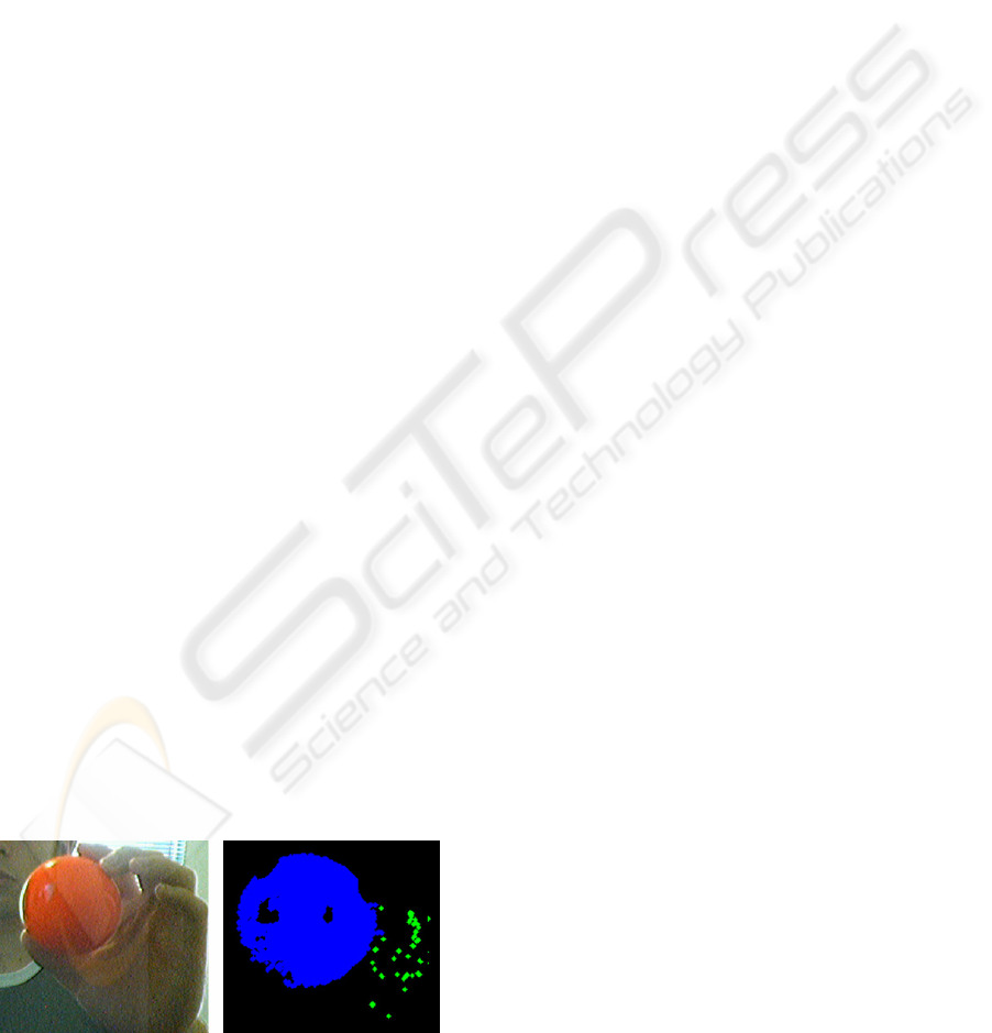
Filtered points are grouped with a connected
components algorithm (Rosenfeld and Pfaltz, 1966)
to determine which belong to the tracked object, and
which belong to the background. Figure 1 shows an
example of threshold results and point grouping.
Figure 1: Threshold and grouping results.
2.1 Real-time colour tracking
Performing the HSV transformation on a complete
frame of original video is expensive, and
unnecessary, as high resolution information is only
required for making a precise determination of
properties of the tracked features. To increase
efficiency, while still locating the tracked object
even under rapid movement, HSV transformation is
performed at two scales.
Transformation and filtering operations are first
performed on a low-resolution version of the frame,
generated by standard graphics hardware. Areas of
the image likely to contain the tracked features are
identified using HSV thresholding. Transformation,
filtering, and grouping are then performed on those
areas of the original, high-resolution frame.
3 SINGLE FEATURE TRACKING
A single feature point with known size and shape
properties was tracked in the initial stage of the
project. By tracking the position of the feature, a
user interface can be constructed where object
motion controls a 2D position. From the size of the
feature in each frame, and the parameters of the
camera, the feature position in 3D space can be
estimated. A coloured ball was selected to provide
this initial feature, due to its sufficiently simple
shape properties. However, other shapes could be
used, provided the centre and bounding sphere could
be reliably estimated.
3.1 2D Feature Tracking
From the chosen pixel group, initial estimates for the
centre and radius of the circular feature are
determined by applying a smallest enclosing disk
algorithm (Nielsen and Nock, 2004) to points around
the edge of the group. The result of this algorithm is
the centre and radius of a circle containing the
complete set of edge points. Estimates are
reasonable, even when substantial sections of the
feature are occluded or lost in thresholding.
However, as this circle encloses all points, single
outlying points can significantly alter the centre and
radius of the disk.
These estimates can be improved by determining
the mean and standard deviation for the distance
between edge points and the initial centre, and
rejecting outliers. Estimates can be further improved
by averaging over a randomised set of centre
estimates, obtained by selecting sets of 3 edge
points, and calculating the centre from the
VISAPP 2006 - MOTION, TRACKING AND STEREO VISION
390
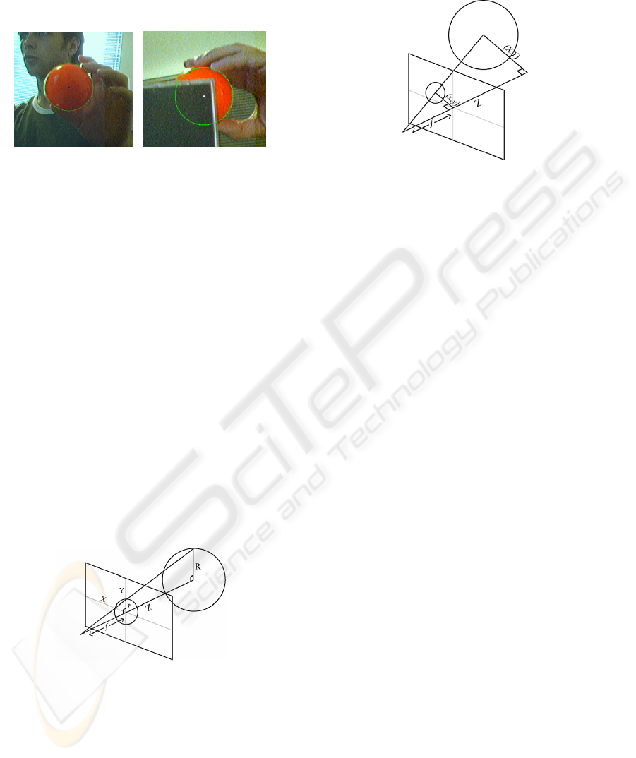
intersection between the normals of lines connecting
the points along the arc of the circle. Final estimates
are shown in Figure 2, including estimates in the
presence of occlusion.
Figure 2: Centre point and enclosing disk.
3.2 3D Feature Tracking
The 2D position and radius estimates for the tracked
feature are used to determine a position in 3D space.
The relationship between a scene and the image
plane of a camera can be modelled through
perspective projection, with a point in space
appearing in the frame at the intersection of the
image plane and a ray between the point and the
camera’s optical centre. As the object is far from the
image plane relative to its own size, the geometry of
the projection can be simplified with a weak
perspective assumption, where all points on the
object are assumed to be approximately the same
distance from the camera (Alter, 1992) The ray
between the camera and the centre of the object is
assumed to be perpendicular to the image plane, as
shown in Figure 3. If the focal length of the camera
and the size of the tracked feature are known,
position in space can be determined from position
and radius in the image.
Figure 3: Weak perspective projection.
The Z position of the feature is determined from
the focal length of the camera f, radius in the frame
r, and radius of the ball R by
/
Z
fR r=
. Having
estimated the distance of the feature from the camera
Z, perspective projection is used to determine the 3D
position of the feature. X and Y coordinates for the
tracked feature, as shown in Figure 4, are
determined from f, Z, and the vector (x,y) from the
centre of the frame to the centre of the feature in the
frame by
(,) (,)/XY Zxy f
=
.
Figure 4: Determining X and Y position.
4 FEATURE PAIR TRACKING
Tracking the movement of a single feature point in
3D is sufficient to create simple 3D user interfaces.
However, control in such an interface is limited to
three degrees of freedom. For more complex control
and interaction, an interface should provide control
over both 3D position and orientation.
To allow for greater degrees of control, a pair of
features were tracked in the next stage of the project
to define a 3D vector, providing a 3D position, and
rotation about two axes. Two easily identified
features were provided by same-coloured markers
on a cylindrical wand. In estimation, the markers are
approximated as rectangular sections of the tracked
wand, with a major and minor axis.
4.1 2D Feature Pair Tracking
Tracking the feature pair requires correctly
determining which group of points corresponds to
which marker in each frame of video. From the
initial set of pixel groups determined by connected
components, any group with number of pixels below
a minimum is rejected. Groups are also rejected if
their distance from either feature in the previous
frame, or the ratio of their size to the size of either
feature, is too great. Thresholds are loose, to discard
only unambiguous outliers. From the remaining
pixel groups, groups corresponding to tracked
features are selected by proximity to features in the
previous frame.
An initial estimate for the centre of each feature
is determined from the smallest enclosing disk
algorithm. Estimates of feature width and length are
obtained by linear searches for edge points along the
line connecting the features in the image and its
normal. Each search begins at a point shifted some
COMPUTER VISION BASED INTERFACES FOR INTERACTIVE SIMULATIONS
391
number of pixels from the estimated centre of a
feature along the perpendicular to the current search
line. Results are averaged over multiple searches.
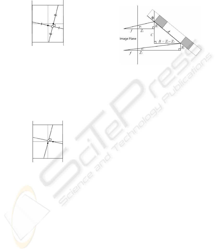
Figure 5: Estimated length and width along connecting
line and its normal.
From the estimated length and width, midpoints
are found for lines across the length and width of the
feature, defined by the relative position of the
features’ centres. These midpoints lie on lines
bisecting the feature, as seen in Figure 5. The
intersection of two lines, centred on the midpoints,
in the direction of the connecting line and its normal,
provides a better estimate of the centroid of the
feature, as shown in Figure 6.
Figure 6: New centroid estimate (hollow circle).
From the improved estimates of the centre of
each feature, the estimate of the connecting line can
also be improved. Iterating this process several times
provides reliable approximations of each feature’s
centre, length, and width.
4.2 3D Feature Pair Tracking
Initial attempts at estimating 3D position and
rotation used feature width to determine Z positions.
However, this proved to be problematic under some
lighting conditions. For a cylinder, shade tends to
vary across its width. Feature width may be incorrect
if one side of the cylinder is in shadow, or if bright
reflections along the length of a feature divide it into
multiple sets of points. These issues can be avoided
by ignoring width, instead using feature length and
the distance between the feature centroids in the
frame. Z position can be determined from this
distance, provided rotation of the wand around the x-
axis is known. Again assuming weak perspective,
the scene can be approximated as seen in Figure 7.
Figure 7: Weak perspective projection.
As
/ii i
f
rZ R
=
, and
12RR=
for features of
equal length,
11 2 2rZ rZ=
, and
21 112()(/1)ZZ Zrr
−
=−
. The distance
21BZ Z=−
,
from which θ can be determined, can therefore be
estimated from one Z position, and the relative
lengths of the two features in the frame,
1r
and
2r
.
As
1r
and
2r
are known, Z position and rotation
around the x-axis can be estimated by finding a Z
position for one feature for which the distance
between the features of the rotated wand, projected
onto the image plane, matches the distance between
the centroids of the features in the frame. The
problem of estimating position and rotation therefore
resolves to a 1D search for a single Z value.
This Z value is determined with a binary search
over the range of distances for which the features
can be reliably tracked. Z position is initialised to the
midpoint of this range. For
11 2(/ 1)BZrr=−
, x-axis
rotation θ is given by
sin( / )BA
θ
=
. Distance
between the features along the y-axis C is given by
/tan( )CB
θ
=
. This distance is projected onto the
image plane, assuming Z position of the midpoint
between the features, as
1/( / 2)cfCZB
=
+
. If this
distance is less than the distance between the centres
of the features in the frame, the upper limit of the
search is set to the Z
1
estimate. Otherwise, it
becomes the lower limit. Through multiple iterations
of this search, reliable estimates are obtained for Z
position and x-axis rotation.
From this Z position, X and Y position can be
estimated by projection through the midpoint
between the feature centroids in the frame, giving all
values for a centre point C. The remaining unknown
is z-axis rotation, initially estimated by the angle α
between a vector connecting the centroids in the
frame and the y-axis. For vector Vc from the centre
of the camera to the centre of the tracked object, and
VISAPP 2006 - MOTION, TRACKING AND STEREO VISION
392
distance between a feature and the centre of the
object A, vector V
E
from the camera centre to a
feature, when the object is rotated by θ around the x-
axis and by the estimate α around the z-axis, is
given by
E
V =
(
.sin()*,
C
Vx A
α
+
. cos( )* cos( )* ,
C
Vy A
α
θ
+
.cos()*sin()*
C
Vz A
α
θ
+
)
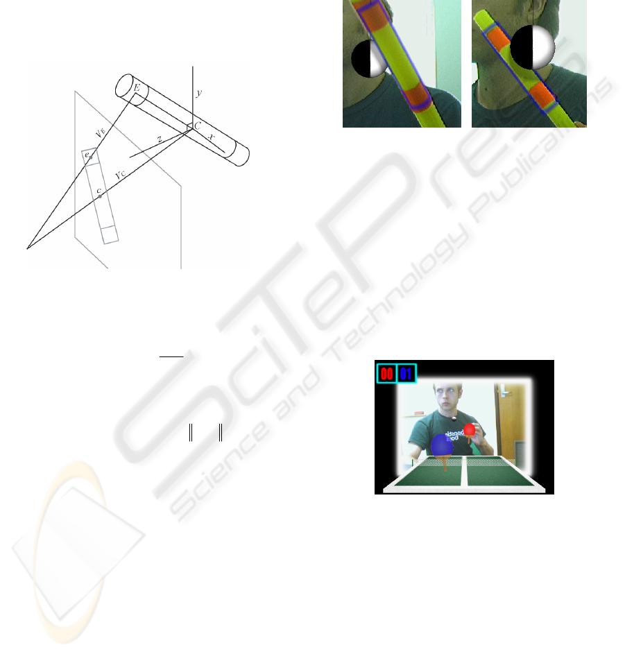
The endpoint of the rotated object is projected
onto the image plane, as shown in Figure 8.
Figure 8: Projection onto the image plane.
V
E
intersects the image plane at point e:
*
.
E
E
f
eV
Vz
=
The angle β between the line connecting e and c
and the y-axis is given by
asin(( . . ) / )ex cx e c
β
=−−
The difference between this value and the initial
estimate is removed from that estimate to give a
final value for z-axis rotation, φ:
2
φ
αβ
=−
The set of values now obtained describe a point
in 3D space and rotations around two axes.
5 INTEGRATING REAL AND
SIMULATED OBJECTS
By determining the location and orientation of an
object in 3D space, motion of the tracked object can
control the motion of a rendered object. A 3D object
(in this case a cylinder) can also be mapped to the
position of the wand in video. Other 3D objects can
be introduced into the scene, and intersect the space
occupied by the cylinder. By redrawing the original
video source over visible areas of the cylinder, the
real and rendered objects appear to occupy the same
3D space. This integration is improved by adding
shadow effects, as seen in Figure 9. Collision
detection and physics simulation enable physical
interaction between the objects.
Figure 9: Integrating in video.
6 DEMONSTRATION
APPLICATIONS
A simple table tennis game, seen in Figure 10, was
developed to demonstrate the ball-tracking interface.
The motion of the ball controls 3D movement of the
user’s paddle. Velocity determines the power of a
shot. This demonstration shows that the 3D ball
interface can provide precise control in real time.
Figure 10: Table Tennis demo.
In the mini golf demo, seen in Figure 11, a basic
golf game is played entirely through the tracked
wand. A rendered golf course is shown in front of
the player. The wand can be used to rotate and view
the course. When the player is ready to make a shot,
holding the wand close to the golf ball triggers a
perspective change to behind the ball, where the
tracked wand controls a rendered golf club.
This application demonstrates the versatility of
the wand interface. The wand is used for selection,
for 3D manipulation of the course, and for physical
interaction between the golf club and the ball.
COMPUTER VISION BASED INTERFACES FOR INTERACTIVE SIMULATIONS
393
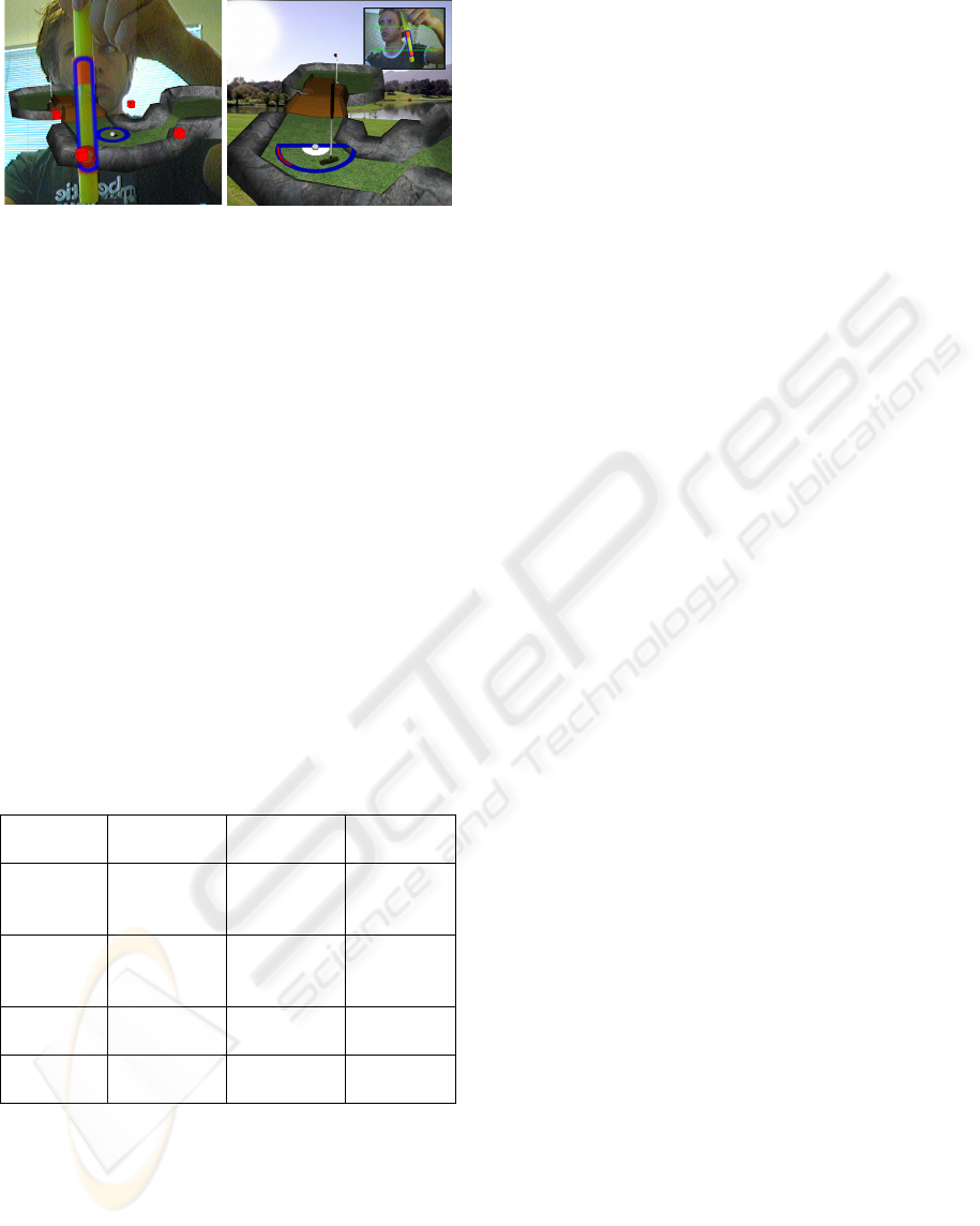
Figure 11: Mini Golf demo.
6.1 Performance
The interface was designed to be sufficiently
accurate to provide intuitive control and create a
convincing visual integration between real and
rendered objects. The accuracy of wand motion and
rotation has been tested in favourable lighting
conditions. Measurements were made at a range of
distances from the camera, with observations
repeated multiple times and compared to ground
truth data. Results, seen in Table 1, predictably show
uncertainty of the position estimates increasing with
distance from the camera. Linear movement
estimates are reasonably accurate, compensating
well for the effect of perspective on motion parallel
and perpendicular to the camera. However, a
substantial degree of inaccuracy is seen in x-axis
rotation estimates at a significant distance from the
camera.
Far (75cm) Mid (55cm) Near
(40cm)
10cm X
Translatio
n
10.03±0.09 10.02±0.06 10.03±0.0
6
10cm Z
Translatio
n
9.98±0.59 8.37±0.20 9.91±0.09
45° Z
Rotation
44.96±0.32 44.94±0.23 45.68±0.2
0
45° X
Rotation
45.28±4.61 39.76±2.76 45.39±1.0
6
In less favourable conditions, the presence of
bright light sources, shadows on the tracked features,
or noise due to low light can degrade performance.
However, a sufficient degree of control can be
achieved in most realistic indoor situations in which
the system was tested. As the tracking system is
based on colour, tracking problems are most
noticeable in situations where the colour of the
tracked features is present in substantial areas of the
background or user.
7 CONCLUSION
This paper has described methods of tracking a
known object in 3D in a single camera, through
properties of recognized features. This tracking is
used to create genuine 3D user interfaces that can be
used for direct interaction with 3D environments
integrating real and simulated objects. These
interfaces are suitable for use in a home
environment, with current computing hardware.
The current system is limited in terms of the
range of objects that can be tracked, requiring
markers to provide identifiable features for tracking
that incorporates rotation. However, the scope of the
fundamental system is broad enough that it could be
substantially extended with future development, and
further demonstrate the implementation and use of
original forms of human-computer interaction.
REFERENCES
Alter, T. D., 1992. 3D Pose from 3 Corresponding points
under weak-Perspective Projection. Technical Report
1378, MIT Artificial Intelligence Laboratory.
Chung, J., Kim, N., Kim, G.J., & Park, C.M., 2002. Real
Time Motion Tracking System For Interactive
Entertainment Applications. Proceedings of the 5th
International Conference on System Simulation and
Scientific Computing.
Haralick, R.M., Sternberg, S.R., & Zhuang, X., 1987.
Image analysis using mathematical morphology. IEEE
Transactions on Pattern Analysis and Machine
Intelligence, Vol. 9, No. 4, pp. 532-550.
Hartley, R., Zisserman, A., 2000. Multiple View
Geometry In Computer Vision, Cambridge University
Press.
Immersion Corporation, http://www.immersion.com
Kim, K., Ramakrishna, R.S., 1999. Vision-Based Eye-
Gaze Tracking for Human Computer Interface.
Proceedings of the IEEE SMC’99 Conference, No.2,
pp. 324-329.
Nielsen, F., Nock, R., 2004. Approximating smallest
enclosing disks. Proceedings of the 16th Canadian
Conference on Computational Geometry, pp. 124-127.
Rosenfeld, A., Pfaltz, J.L., October 1966. Sequential
operations in digital picture processing. Journal of the
ACM, Vol. 13, No. 4, pp. 471-494.
Smith, A.R., 1978. Color Gamut Transform Pairs.
Proceedings of SIGGRAPH 78, pp. 12-19.
Sony EyeToy, http://eyetoy.com
Yang, M-H., Ahuja, N., 1999. Recognizing hand gesture
using motion trajectories. Proceedings of the IEEE CS
Conference on Computer Vision and Pattern
Recognition, pp. 468-472.
Table 1: Mean values and standard deviation for estimates
of movement in 3D space.
VISAPP 2006 - MOTION, TRACKING AND STEREO VISION
394
