
3D TRACKING USING 2D-3D LINE SEGMENT
CORRESPONDENCE AND 2D POINT MOTION
Woobum Kang
Kyoto Univirsity
∗
Gokasho, Uji, Kyoto 611-0011 Japan
Shigeru Eiho
The Kyoto College of Graduate Studies for Informatics
7 Monzen-cho, Tanaka, Sakyo-ku, Kyoto 606-8225 Japan
Keywords:
3D tracking, CAD model, edge, feature point.
Abstract:
In this paper, we propose a 3D tracking method which integrates two kinds of 2D feature tracking. Our tracker
searches 2D-3D correspondences used to estimate camera pose on the next frame from detected straight edges
and projected 3D-CAD model on the current frame, and tracks corresponding edges on the consecutive frames.
By tracking tho se edges, our tracker can keep correct correspondences even when large camera motion occurs.
Furthermore, when the estimated pose seems incorrect, our tracker brings back to the correspondences of the
previous frame and proceeds tracking of corresponding edges. Then, on the next frame, our tracker estimates
the pose from those correspondences and can recover to the correct pose.
Our tracker also detects an d tracks corners on the image as 2D feature points, and estimates the camera pose
from 2D-3D line segment correspondences and the motions of feature points on the consecutive frames. As
the result, our tracker can suppress the influence of incorrect 2D-3D correspondences and can estimate the
pose even when the number of detected correspondences is not enough.
We also propose an approach which estimates both the camera pose and the correspondences. With this
approach, our tracker can estimate the pose and the correspondence on the initial frame of the tracking.
From experimental results, we confirmed our tracker can work in real-time with enough accuracy for various
applications even with a less accurate CAD model and noizy low resolution images.
1 INTRODUCTION
Image-based markerless 3D tracking is one of the im-
portant issues. One of the well-known approaches for
the 3D tracking, called as model-based approach, esti-
mates the camera pose from 2D-3D correspondences
between 2D feature and 3D model. As there are many
approaches (Liu et al., 1990), (Christy and Horaud,
1999) to estimate the pose from various kinds of 2D-
3D feature correspondence (line, point, etc.), we can
estimate the pose correctly if sufficient number of cor-
respondences are obtained on every frame of tracking.
However, this is difficult in the real situation. Various
corresponds estimation approaches for model-based
3D tracking have been proposed. Lowe (Lowe, 1992)
proposed an edge-based iterative pose and correspon-
dence estimation approach provided that approximate
pose is obtained as the initial guess. Drummond et
1
Most part of this research was done when the authors
belonged to Kyoto University. The first author currently
works for KEYENCE Corp.
al. (Drummond and Cipolla, 2002) proposed real-
time 3D tracking method using the 2D-3D edge point
correspondence.
The weaknesses of 2D-3D model based approach
are: (1)They cannot estimate or misestimate when
the number of correspondences is not sufficient due
to motion blur or measurement error of both 3D
model and intrinsic parameters of the camera. (2)In
the methods such as (Lowe, 1992) and (Drummond
and Cipolla, 2002), which estimate 2D-3D correspon-
dences by projecting the 3D model using the pose
on the previous frame and nearest 2D feature search,
once the tracker estimates an incorrect pose, it cannot
obtain correct correspondences on the latter frames.
Vacchetti et al. (L. Vacchetti and Fua, 2004b)
proposed a tracking method using 2D-3D feature
point correspondences and feature point motions for
the pose estimation. They also proposed a track-
ing method(L. Vacchetti and Fua, 2004a) which inte-
grates their feature-point-based method(L. Vacchetti
and Fua, 2004b) and the edge-based methods pro-
posed in (Drummond and Cipolla, 2002), (Comport
278
Kang W. and Eiho S. (2006).
3D TRACKING USING 2D-3D LINE SEGMENT CORRESPONDENCE AND 2D POINT MOTION.
In Proceedings of the First International Conference on Computer Vision Theory and Applications, pages 278-285
DOI: 10.5220/0001365402780285
Copyright
c
SciTePress

et al., 2003). By integrating 2D feature motions on
the consecutive frames, they cover the first weakness
of model-based approach. However, their tracker can
only use the feature points on the surface of tracked
object and does not use those on the back ground.
We here propose a markerless 3D tracking method
which combines image-based 2D feature tracking.
We estimate the pose from 2D-3D correspondences
between straight edges and 3D line segments of the
CAD Model and feature point motions on the consec-
utive frames, where the corners detected on the image
are used as the feature points.
Different from the method proposed on (L. Vac-
chetti and Fua, 2004b), our method does not re-
strict the position of feature points and can han-
dle large camera motions by using a strong image-
based straight edge tracking method. Moreover, by
introducing special 2D-3D correspondence update
process, our tracker can keep 2D-3D correspondences
and can track corresponding edges even if quite a
wrong pose is estimated for some numerical failures.
And our tracker can recover to the correct pose on the
latter frame by estimating the pose from stored cor-
respondences obtained just before the incorrect pose
estimation.
On the initial frame of our 3D tracking, it is nec-
essary to obtain the 2D-3D correspondences and the
pose. We also propose a method which estimates both
the pose and the correspondence by using the approx-
imate initial guess of the pose. With this method, our
tracker can estimate the pose and the correspondence
on the initial frame automatically.
2 OVERVIEW OF OUR 3D
TRACKING METHOD
Our 3D tracker estimates the camera pose relative
to the world coordinate system on every frame de-
rived from a single camera. We assume that intrin-
sic parameters of the camera are known. We esti-
mate the camera pose from (1) 2D-3D line segment
correspondences between straight edges detected on
the image and CAD model, and (2) motions of the
feature points on the consecutive frames. We use
corners on the image extracted with Tomasi-Kanade
method(Shi and Tomasi, 1994) as the feature points.
Our tracker tracks these points on the consecutive
frames by calculating their optical flow using Lucas-
Kanade method(Lucas and Kanade, 1981), and uses
their motions to estimate the pose. We assume that the
pose and the 2D-3D line segment correspondences on
the initial frame are provided.
We explain the outline of our method using fig.1.
(I) shows projected 3D CAD model (thin line),
straight edges corresponding to the model line seg-
I II III
IV
V
VI
Figure 1: Straight edge and feature point tracking, pose es-
timation, and 2D-3D correspondence update. [ I:Projected
CAD model (thin line), edges corresponding to the model
(bold line), and detected feature points. II:Edges detected
on the next frame of I. III:Our tracker tracks edges corre-
sponding to the model (solid bold line) and motions of fea-
ture points. IV and V:Our tracker estimates the pose from
2D-3D line segment correspondences and feature point mo-
tions. VI:Our tracker eliminates incorrectly corresponding
edges (dashed gray line) and searches newly found corre-
sponding edges (solid gray line). ]
ments (bold line), and detected feature points. When
the new frame comes in, our tracker tracks the edges
corresponding to the model line segments and fea-
ture points detected on the previous frame shown as
figures (II) and (III). By tracking those edges on the
consecutive frames, our tracker can estimate the cor-
rect position of those edges even when the large cam-
era motion occurs. After the 2D feature tracking, our
tracker eliminates outliers of motions of feature points
by fitting fundamental matrix with LMedS method.
Then, as figure (IV), our tracker estimates the pose
from both 2D-3D line segment correspondences and
feature point motions on the consecutive frames. Af-
ter the pose estimation, shown as the figures (V)
and (VI), 2D-3D line segment correspondences are
updated by checking the distances between straight
edges detected on the current frame and projected 3D
CAD model lines.
3 STRAIGHT EDGE TRACKING
AND CORRESPONDENCE
UPDATE
3.1 Straight Edge Tracking and
Detection
Straight edges corresponding to the 3D model line
segments are tracked on the consecutive frames. This
straight edge tracking is performed from two steps,
estimation and matching.
3D TRACKING USING 2D-3D LINE SEGMENT CORRESPONDENCE AND 2D POINT MOTION
279
On the estimation step, our edge tracker estimates
the motion of the edge by calculating optical flow of
all edge pixels for every tracked straight edge. And
the tracker fits a line from calculated destinations of
edge pixels and eliminates outliers. If those destina-
tions are not on a line, our tracker regards the estima-
tion was failed and stops tracking for the edge.
On the matching step, our tracker searches the
edges near the estimated destination. If straight edges
exist around there, the tracker regards one on the near-
est as the corresponding one. If there is no corre-
sponding edge but most destinations of the edge pix-
els are on a line, the tracker constructs a straight edge
from estimated destinations of edge pixels and re-
gards it as the corresponding one. Unlike the straight
edge tracking method proposed by Chiba et al. (Chiba
and Kanade, 1998), our edge tracker can track even
when the corresponding edge is not detected properly
due to motion blur and illumination changes.
On every frame, our tracker detects straight edges
on the image by using Canny edge detector(Canny,
1986) for the edge detection. Like the method pro-
posed by Lowe(Lowe, 1987), our tracker detects
straight edges by splitting connected edges until all
split edges become straight. Then, to reduce the
fragments, edges on the neighbor and on a line are
merged.
3.2 Correspondence Update Process
After estimating the pose, our tracker updates 2D-
3D correspondences by checking the distances be-
tween projected 3D model line segments and straight
edges. In the model projection, hidden lines are re-
moved in order to suppress incorrect 2D-3D corre-
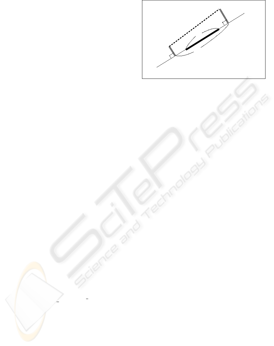
spondences. We define the distance and the over-
lapping ratio between straight edge and correspond-
ing projected model line segment using the distances
d
1
, d
2
and the lengths l, l
0
as shown in fig.2. Where
d
1
, d
2
is defined as the point-to-line distance between
each end point of the projected 3D line segment and
the line obtained by extending the straight edge. We
define the distance d and the overlapping ratio γ as
follows.
d =
1
2
d
2
1
+ d
2
2
1
2
γ = l/l
0
(1)
Correspondence update is done by the following
two steps; (1) elimination of incorrect correspon-
dences from those currently used for the pose estima-
tion, and (2) addition of new correspondences.
On the elimination step, our tracker calculates
the distance for every 2D-3D line segment pair cur-
rently regarded as corresponding each other, and es-
timates the standard deviation of distances ˆσ
d
us-
ing MAD(Median Absolute Deviation)(G.A.F. Seber,
1981). Then, the correspondences whose distances
d
1
d
2
l'
l
Projected Model
Line Segment
Corresponding
Edge
Figure 2: Distance and overlapping ratio between a 3D
model line segment and corresponding straight edge.
d are larger than βˆσ
d
are regarded as incorrect ones
and eliminated, where β is a constant and its value is
around 2-3. As threshold βˆσ
d
becomes very large if
the large displacements occur between the projected
models and its corresponding edges, our tracker keeps
2D-3D correspondences of the previous frame if quite
a different pose is estimated.
On the addition step, our tracker searches new cor-
respondences by checking the distances between pro-
jected model line segments and straight edges, both of
which has no corresponding edge or no corresponding
model line segment. If their distance is d < d
corres
and the overlapping ratio is γ > γ
corres
, our tracker
adds this pair to the correspondences which are used
in the pose estimation, where d
corres
and γ
corres
are
constants, and we set d
corres
around 2-3[pixel] and
γ
corres
= 0.3.
4 POSE ESTIMATION FOR THE
TRACKING
4.1 Pose from Known 2D-3D Line
Segment Correspondence
In this method, we estimate the pose by minimizing
the following objective function:
f(R
n
, t
n
) =
L
X
l=1
w
l
φ
2
l
+ g(R
n
) (2)
where φ
l
(R
n
, t
n
) is error term in 2D-3D correspon-
dence, g(R
n
) is constraint term for rotation matrix
R
n
, and w
l
is weighting coefficients introduced to
eliminate outliers.
We define the correspondence error between a 2D
line segment (straight edge) and corresponding 3D
line segment as follows: Considering fragments of
VISAPP 2006 - MOTION, TRACKING AND STEREO VISION
280

straight edges, we define the error as the sum of point-
to-line distances between each end point of projected
3D line segment and extended straight edge as fig. 2.
When one of the end points of a 3D line segment
is represented as X = [X, Y, Z]
T
in the world coor-
dinate system and represented as X
0
= [X
0
, Y
0
, Z
0
]
T
in the camera coordinate system, the relationship be-
tween X and X
0
is described as follows:
X
0
= RX + t (3)
Therefore, squared point-to-line distance between
projected end point and 2D line l : ax + by + c =
0(a
2
+ b
2
= 1) is described as follows.
d
2
=
a
X
0
Z
0
+ b
Y
0
Z
0
+ c
2
(4)
By substituting 1/Z
0
to a scale parameter µ in order
to simplify the objective function, the distance is de-
scribed as follows;
d
02
= µ
2
(aX
0
+ bY
0
+ cZ
0
)
2
= µ
2
n
T
X
0
2
= µ
2
n
T
(RX + t)
2
(5)
where n = [a, b, c]
T
. Then, 2D-3D line segment cor-
respondence error is defined as squared sum of d
0
.
When a 2D line segment l
i
is corresponding to the 3D
line segment L
j
, its correspondence error φ becomes:
φ(l
i
, L
j
, R, t) =
2
X
k=1
µ
2
jk
n
T
i
(RX
jk
+ t)
2
(6)
where X
jk
(k = 1, 2) is end point of the 3D line seg-
ment L
j
and µ
jk
is its scale parameter.
Weighting coefficient w
l
is determined from corre-
spondence error φ
l
. We set w
l
from Tukey’s ρ func-
tion;
w =
(
h
1 −
x
C
2
i
2
|x| ≤ C
0 |x| ≥ C
x =
e
ˆσ
(7)
where e is the error (φ
l
for w
l
) and C is a constant.
To determine w
l
from eq.7, it is necessary to estimate
the standard deviation of errors. According to MAD,
standard deviation is estimated as;
ˆσ
MAD
= 1.4826 median {|φ
1
|, ..., |φ
L
|} (8)
If we use MAD, however, 2D-3D correspondences
necessary to estimate the pose uniquely are some-
times regarded as outliers. We therefore set ˆσ from
maximum absolute correspondence error of those
necessary to estimate the pose uniquely if the plenty
number of correspondences are not obtained. By writ-
ing this maximum absolute error as |φ
0
|, ˆσ is deter-
mined as follows.
ˆσ = max{1.4826|φ
0
|, ˆσ
MAD
} (9)
To decrease the number of variables, we represent
rotation component of the pose by a quaternion r
n
instead of a rotation matrix R
n
. The number of vari-
ables representing the camera pose is reduced from
twelve (nine for R
n
and three for t
n
) to seven (four
for r
n
and three for t
n
). The objective function is
rewritten as follows;
f(r, t) =
L
X
l=1
w
l
φ
2
l
+ g(r) (10)
On the above equation, g(r) becomes the constraint
term for the rotation quaternion. The minimization
of the objective function is done by repeating weight-
ing coefficients determination and pose parameter es-
timation. Pose parameter estimation is done by us-
ing nonlinear minimization techniques such as Gauss-
Newton approach. The estimation procedure is de-
scribed as follows.
1. Set coefficients as w
1
= w
2
= ... = w
L
= 1 and
set R
n−1
, t
n−1
as initial guess of the pose parame-
ters R
n
, t
n
.
2. Update the pose parameter by the following proce-
dure.
(a) Compute the scale parameters µ
lk
= 1/Z
0
lk
,
(k = 1, 2) and ν
m1
, ν
m2
from currently esti-
mated pose R
n
, t
n
.
(b) Convert R
n
to a quaternion r
n
, and update the
pose to the one which decreases f(r
n
, t
n
). Then,
convert updated r
n
to a rotation matrix and sub-
stitute it to R
n
.
(c) Repeat above procedure until the objective func-
tion converges.
3. Calculate φ
l
and ψ
m
, and update the coefficients
w
l
.
4. Repeat 2 and 3 until the objective function becomes
sufficiently small.
4.2 Pose from Known 2D-3D
Correspondences and Motion
Constraints
In this method, we add the motion constraint errors to
the objective function of eq.2. The objective function
becomes as follows:
f(R
n
, t
n
) =
L
X
l=1
w
l
φ
2
l
+
M
X
m=1
w
0
m
ψ
2
m
+ g(R
n
) (11)
where ψ
m
(R
n
, t
n
) is the motion constraint error. ψ
is defined from epipolar constraints for the motion of
feature points on the consecutive frames.
3D TRACKING USING 2D-3D LINE SEGMENT CORRESPONDENCE AND 2D POINT MOTION
281

When 2D coordinates of a feature point on n − 1
and n-th frame are x
n−1
and x
n
respectively, epipo-
lar lines for x
n−1
, x
n
are represented by the follow-
ing vectors.
n
1
= ν
1
E
T
˜
x
n
= [a
1
, b
1
, c
1
]
T
n
2
= ν
2
E
˜
x
n−1
= [a
2
, b
2
, c
2
]
T
(12)
where E is the essential matrix composed of camera
motion parameters on the consecutive frames (R
0
, t
0
),
ν
1
, ν
2
are the scale parameters set to satisfy a
2
k
+b
2
k
=
1(k = 1, 2) , and
˜
x is the homogeneous representa-
tion of 2D point x, i.e.,
˜
x = [x, y, 1]
T
. Squared error
ψ
2
is defined as follows.
ψ
2
=
n
T
1
˜
x
n−1
2
+
n
T
2
˜
x
n
2
=
ν
2
1
+ ν
2
2
˜
x
T
n
E
˜
x
n−1
2
=
ν
2
1
+ ν
2
2
˜
x
T
n
{t
0
× (R
0
˜
x
n−1
)}
2
(13)
Then, we express the right side of eq.13 by cam-
era pose parameters R
n−1
, t
n−1
, R
n
, t
n
using the fol-
lowing equation which represents the relationship be-
tween the motion and the pose on each frame.
R
n
= R
0
R
n−1
t
n
= R
0
t
n−1
+ t
0
(14)
As we know the pose parameter on (n − 1)-th frame
R
n−1
, t
n−1
, ψ
2
becomes the function of the pose pa-
rameter on n-th frame R
n
, t
n
.
Same as the method of 4.1, we represent the ro-
tation component by a quaternion, and estimate the
pose by repeating weight coefficients determination
and pose parameter estimation.
4.3 Pose from Decomposition of
Essential Matrix and 2D-3D Line
Correspondences
Essential matrix is composed of rotation and transla-
tion components of the camera motion R
0
and t
0
, and
those parameters are obtainable by decomposing es-
sential matrix by using SVD(Hartley and Zisserman,
2000). However, motion parameters cannot be de-
termined uniquely from SVD method. We need to
choose rotation components from two rotation matri-
ces R
0
1
, R
0
2
obtained by the decomposition, and also
need to determine the scale of translation vector t
0
.
We therefore estimate the pose by the following pro-
cedure:
1. Decompose the essential matrix estimated from
feature point motions and calculate R
0
1
, R
0
2
,
¯
t
0
.
2. Choose R
0
from R
0
1
and R
0
2
, and determine the
scale of t
0
from 2D-3D line correspondences which
are easily obtained from existing 2D-3D line seg-
ment correspondences.
In the following discussion, we represent 3D line L
by point P on the line and direction D. Any point X
on line L is represented using coefficient κ as X =
P + κD. When a 3D line L is corresponding to the
2D line l, there exists the following equation:
n
T
RD = 0
n
T
(RP + t) = 0
(15)
From eqs.14 and 15, and representing the translation
vector t
0
as the product of scale parameter α and nor-
malized vector
¯
t
0
(t
0
= α
¯
t
0
), we obtain the following
equations.
n
T
(R
0
R
n−1
D) = 0 (16)
n
T
R
n
P +
R
0
t
n−1
+ α
¯
t
0
= 0 (17)
At first, we choose rotation matrix R
0
from R
0
1
and
R
0
2
. We can regard the value of left side of eq.16 as
2D-3D line correspondence error, and we choose R
0
which gives less median of absolute error. If 2D-3D
line correspondences (l
i
, L
i
), (i = 1, 2, ..., M) are
obtained on the n-th frame and two rotation matrices
R
0
1
and R
0
2
appear, R
0
is chosen from the following
equation.
R
0
= arg min
R
0
k
e
k
(k = 1, 2) (18)
e
k
= median
i
n
T
i
(R
0
k
R
n−1
D
i
)
(i = 1, 2, ..., M)
Next, the scale parameter α is obtainable from
eq.17 as follows:
α = −
n
T
(R
n
P + R
0
t
n−1
)
n
T
¯
t
0
(19)
This scale parameter is computed from every line cor-
respondences (l
i
, L
i
) and denoted as α
i
, then, we set
the scale parameter α as the median of α
i
:
α = median
i
α
i
(20)
By using the median of parameters in the estima-
tion process, we can eliminate the influence of some
incorrect correspondences.
4.4 Switching the Two Pose
Estimation Methods
On every frame, our tracker checks whether it has suf-
ficient number of 2D-3D correspondences to estimate
the pose from 2D-3D correspondences alone. If it
has, it estimates the pose by the method of section
4.2. Otherwise, the method of section 4.3 is used for
estimation.
If there are the sufficient number of 2D-3D corre-
spondences, the tracker also estimates the pose from
2D-3D correspondence alone using the method of
section 4.1. Then, the tracker computes the maximum
VISAPP 2006 - MOTION, TRACKING AND STEREO VISION
282

absolute errors |φ
0
| of those two estimated poses, and
chooses the pose whose |φ
0
| is smaller. By this choice
of the pose from two, the tracker can estimate correct
pose even when one of the estimated pose becomes
quite wrong for various reasons. Especially, on the
next frame after the incorrect pose is estimated, the
feature motion constraint becomes incorrect because
R
n−1
and t
n−1
are incorrect, and only 2D-3D corre-
spondences are correct. On such frames, the tracker
can obtain the correct pose estimated from 2D-3D
correspondences alone.
5 POSE AND
CORRESPONDENCES
ESTIMATION ON THE INITIAL
FRAME
On the initial frame of the tracking, it is necessary
to know the camera pose and the 2D-3D line seg-
ment correspondence. However, it is difficult to esti-
mate the pose and the correspondences automatically
if the tracker doesn’t have any prior knowledge about
the pose. In this section, we propose a method that
estimates camera pose and 2D-3D line segment cor-
respondences simultaneously provided that we know
approximate camera pose (initial guess).
5.1 Automatic Camera Pose and
2D-3D Line Correspondence
Estimation
This method is based on ICP-algorithm(Besl and
McKay, 1992) and integrates robust statistics tech-
niques, and can estimate camera pose and correspon-
dences simultaneously.
Our method is composed of two steps, namely cor-
respondence step and pose step, just like EM algo-
rithm. On the correspondence step, correspondences
between 2D line segments l = {l
1
, l
2
, ..., l
i
, ..., l
M
},
and 3D line segments L = {L
1
, L
2
, ..., L
j
, ..., L
N
}
are fixed from the currently estimated camera pose.
On the pose step, the pose is reestimated from those
correspondences. These two steps repeat until the
pose parameter converges.
On the correspondence step, 3D line segments are
projected using the currently estimated pose. Then,
the 2D line segment corresponding to a 3D line seg-
ment is determined as the one whose absolute line
segment correspondence error |φ| defined on eq.6 is
the smallest. 2D line segment l
0
j
corresponding to the
3D line segment L
j
is determined as the following
equation.
l
0
j
= arg min
l
i
|φ(l
i
, L
j
, R, t)| (21)
On the pose step, camera pose is updated from
the correspondences fixed above. We introduce the
weighting coefficients again to decrease the bad ef-
fects of incorrect correspondences. The objective
function used for updating the pose parameter is de-
scribed as follows.
f(r, t) =
N
X
j=1
w
j
φ
2
(l
0
j
, L
j
, r, t) + g(r) (22)
Coefficient w
j
is determined from the correspondence
error φ(l
0
j
, L
j
, r, t) and eq.7, and it is necessary to
estimate standard deviation ˆσ of line segment corre-
spondence errors. If half or more correspondences
are incorrect, we cannot correctly estimate ˆσ using
MAD. We therefore determine ˆσ not from the distri-
bution of φ but from the number of iteration. That is,
we use large value of ˆσ so that every coefficient w
j
has almost the same value on the initial few iterations
and gradually decrease ˆσ as the number of iteration
increases, and gradually regard the correspondences
that have large errors as incorrect and give less ef-
fect to pose update process. Overall procedure of our
method is described as follows.
1. Set ˆσ = ˆσ
0
.
2. Repeat the following procedure until the pose para-
meter converges.
(a) For every 3D line segmentL
j
, determine corre-
sponding 2D line segment l
0
j
from eq.21.
(b) Set coefficient w
j
from eq.7.
(c) Update pose parameter to the one which de-
creases the value of objective function f(r, t).
(d) for next iteration, set ˆσ := γˆσ (γ < 1)
5.2 Initial Pose and
Correspondences Estimation
We applied this method to the initial pose and corre-
spondence estimation problem. As we know the ap-
proximate initial guess of the camera pose, we can
restrict candidates for the true correspondences on the
first. To exclude the correspondences whose projected
model line segment is not overlapping to the corre-
sponding straight edge at all, we calculate the dis-
tances and the overlapping ratios defined on eq.1 for
all possible 2D-3D correspondences and adopt only
the correspondences as candidate whose distance is
below d
init
and overlapping ratio is above γ
init
.
As we restrict the correspondences at first, it is nec-
essary to use criteria different from the one described
in eq.21. We use the following criteria on the corre-
spondence step of estimation.
l
0
j
= arg min
l
i
∈l
0
j
|φ(l
i
, L
j
, R, t)| (23)
3D TRACKING USING 2D-3D LINE SEGMENT CORRESPONDENCE AND 2D POINT MOTION
283
Where l
0
j
is the 2D line segments that are candidates
for the one corresponding to the 3D line segment L
j
.
After the estimation, it is necessary to choose the
true correspondences from ones obtained on the cor-
respondence step. As we have already obtained ac-
curate camera pose, we determine the 2D-3D line
segment correspondences same as the correspondence
addition process described in section 2.
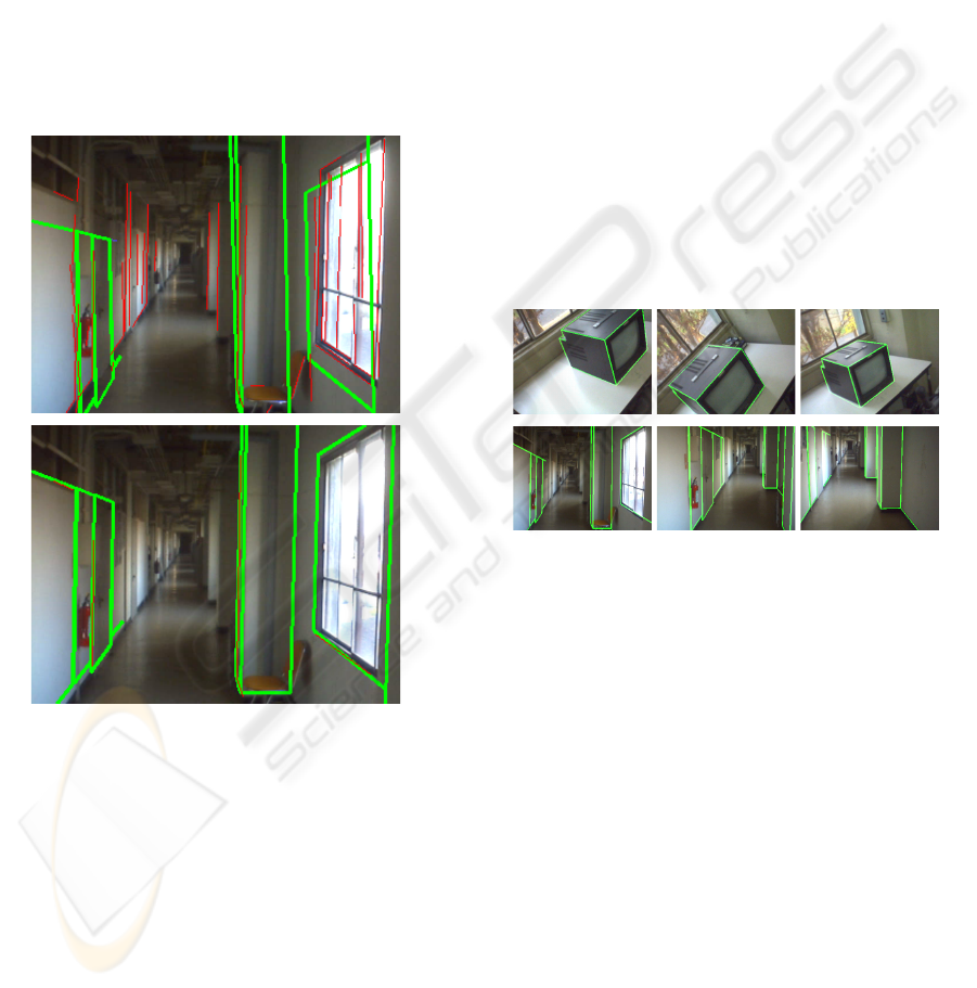
We applied this method to the pose and correspon-
dences estimation on the initial frame of tracking. The
top of fig.3 shows initial guess of the camera pose
(bold line) and the straight edges which are the candi-
date edges of those corresponding to 3D-Model line
segments (thin line), and the bottom shows accurately
estimated camera pose using our method.
Figure 3: Initial pose and correspondence estimation (Top :
Initial guess of the pose and candidates for the correspond-
ing edges, Bottom : Accurately estimated pose and edges
corresponding to the line segments of CAD model.
6 EXPERIMENTAL RESULTS
To evaluate our method, we took the motion image
sequences of an object in a room (a CRT display) and
a corridor scene. We used a conventional USB cam-
era (Creative Webcam Pro eX, image size:320×240
pixels) which was calibrated with a conventional cal-
ibration software. We prepared CAD models of CRT
display and corridor scene by measuring its 3D con-
tours by hand. Because of the measurement error in
the CAD model and intrinsic parameters of the cam-
era, displacements sometimes appear between the tar-
get objects on the image and the projected model al-
though we carefully estimated the correct pose by
hand.
We have tested on two image sequences which
are 1000 frames sequence for the CRT display and
300 frames sequence for the corridor scene, and our
tracker could track in those sequences well. Snap-
shots from tracking result are shown in fig.4.
Our tracker can track even when the camera moves
rapidly. An example of such cases is shown in fig.5.
Our tracker can also recover to correct pose even if
once it estimates a incorrect pose. Fig.6 shows an ex-
ample of such scene. The pose on the left side is ap-
parently wrong and large displacements appear. How-
ever, we could get the pose with less displacement on
the next frame as shown in right side.
Figure 4: Projected CAD model using tracking results
(Top:CRT display[1000frames sequence], Bottom:corridor
scene[300frames sequence]).
One of the reasons for the incorrect pose estima-
tion is the failure of numerical minimization in the
pose estimation. As we use nonlinear minimization
techniques for the estimation, the parameter some-
times falls into a local minimum and the tracker
misestimates the pose. We have tried several non-
linear minimization methods such as proposed by
Phong et al.(Phong et al., 1995) and Powell’s Dog-
leg method(Powell, 1970). However, the results were
not good enough.
We implemented the tracker with C++ language
and the program is not fully optimized. Even with this
program, our tracker could track on 15-20 fps with
a conventional PC (CPU : Intel Pentium4 Processor
2.2GHz, 1GB memory). We believe that our method
can easily track over 30fps by using optimized pro-
gram and a faster PC.
VISAPP 2006 - MOTION, TRACKING AND STEREO VISION
284
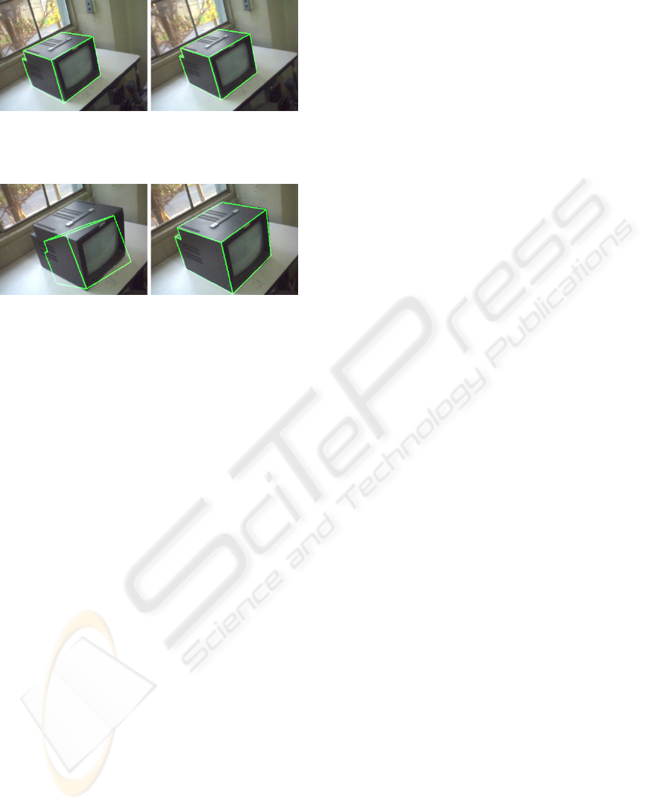
Figure 5: Projected model on the consecutive frames with
large camera motion (Distance between the target on each
frame are approximately 15-20pixels).
Figure 6: Recovery from incorrect pose (Left : Incorrectly
estimated pose, Right : Correctly estimated pose on three
frames later from the left image).
7 CONCLUSIONS
In this paper, we proposed a 3D tracking method
which integrates the 2D feature tracking. By track-
ing edges and holding 2D-3D correspondences, our
tracker can handle large camera motions and can re-
cover to the correct pose even once the pose estima-
tion fails. Moreover, our tracker estimates the pose
from both 2D-3D line segment correspondences and
motions of feature points. By fusing those two kinds
of information, the tracker can suppress the influ-
ence of the incorrect correspondence and can track
even when the sufficient number of 2D-3D correspon-
dences are not obtained. We also proposed automatic
camera pose and 2D-3D correspondences estimation
method and succeeded to estimate the pose and corre-
spondences on the initial frame automatically. From
the experiments, we confirmed our tracker can track
in real-time with noizy low resolution images taken
by a cheap USB camera.
As the future work, we intend to measure the 3D
position of feature points appeared during the tracking
from their 2D positions and estimated poses on a few
frame, then, continue 2D tracking for them and use
their 2D-3D correspondences on the latter frame of
the 3D tracking.
REFERENCES
Besl, P. J. and McKay, N. D. (1992). A Method for Reg-
istration of 3-D Shapes. IEEE Trans. Pattern Anal.
Mach. Intell., 14(2):239–256.
Canny, J. (1986). A computational approach to edge de-
tection. IEEE Trans. Pattern Anal. Mach. Intell.,
8(6):679–698.
Chiba, N. and Kanade, T. (1998). A Tracker for Broken and
Closely Spaced Lines. In ISPRS ’98, volume XXXII,
pages 676 – 683.
Christy, S. and Horaud, R. (1999). Iterative Pose Compu-
tation from Line Correspondences. CVIU, 73(1):137–
144.
Comport, A., Marchand, E., and Chaumette, F. (2003). A
real-time tracker for markerless augmented reality. In
ISMAR’03, pages 36–45.
Drummond, T. and Cipolla, R. (2002). Real-Time Visual
Tracking of Complex Structures. IEEE Trans. Pattern
Anal. Mach. Intell., 24(7):932–946.
G.A.F. Seber, C. (1981). Nonlinear Regression, chapter 14.
Wiley.
Hartley, R. I. and Zisserman, A. (2000). Multiple View
Geometry in Computer Vision. Cambridge University
Press.
L. Vacchetti, V. L. and Fua, P. (2004a). Combining Edge
and Texture Information for Real-Time Accurate 3D
Camera Tracking. In ISMAR’04, pages 48–57.
L. Vacchetti, V. L. and Fua, P. (2004b). Stable Real-Time
3D Tracking Using Online and Offline Information.
IEEE Trans. Pattern Anal. Mach. Intell., 26(10):1385–
1391.
Liu, Y., Huang, T. S., and Faugeras, O. D. (1990). Determi-
nation of Camera Location from 2-D to 3-D Line and
Point Correspondences. IEEE Trans. Pattern Anal.
Mach. Intell., 12(1):28–37.
Lowe, D. G. (1987). Three-Dimensional Object Recogni-
tion from Single Two-Dimensional Images. Artificial
Intelligence, 31(3):355–395.
Lowe, D. G. (1992). Robust model-based motion track-
ing through the integration of search and estimation.
IJCV, 8(2):113–122.
Lucas, B. and Kanade, T. (1981). An Iterative Image Reg-
istration Technique with an Application to Stereo Vi-
sion. In IJCAI’81, pages 674–679.
Phong, T., Horaud, R., Yassine, A., and Tao, P. (1995). Ob-
ject Pose from 2-D to 3-D Point and Line Correspon-
dences. IJCV, 15(3):225–243.
Powell, M. J. D. (1970). A Hybrid Method for Non-linear
Equations. In Rabinowitz, P., editor, Numerical Meth-
ods for Non-linear Equations, pages 87–114. Gordon
and Breach.
Shi, J. and Tomasi, C. (1994). Good Features to Track. In
CVPR’94.
3D TRACKING USING 2D-3D LINE SEGMENT CORRESPONDENCE AND 2D POINT MOTION
285
