
CALCULATION OF OPTIMAL TRAJECTORY IN 3-D
STRUCTURED ENVIRONMENT BY USING GEODESY AND
MATHEMATICAL MORPHOLOGY
Santiago T. Puente, Fernando Torres, Francisco Ortiz, Pablo Gil
Department of Physics, Systems Engineering and Signal Theory. University of Alicante, P.O. Box 99, 03080 Alicante, Spain
Keywords: 3-D mathematical morphology; disassembly trajectory; geodesic paths.
Abstract: A new method for obtaining the optimal path to disassembly an object in a 3-D structure is presented in this
paper. To obtain
the optimal path, we use an extension of the mathematical morphology and the geodesic
distance to 3-D sets. The disassembly algorithm is based on the search for a path of minimum cost by using
the wave-front of the geodesic distance. Cost is considered to be the number of changes in trajectory
required to be able to remove the object. The new method will be applied to disassembly objects in several
3-D environments. The result path for removing an object in a concrete 3-D set will be shown.
1 INTRODUCTION
A method for obtaining the optimal trajectory from
an initial point to a final point in a 3-D space is
presented in this paper. When the trajectory is
computed from the initial point to the final
destination, the following factors must be taken into
consideration:
• Avoiding collisions with the environment: as
there is a structure
d environment, the path between
the two points must avoid any collisions between the
moving object and the environment.
• The shortest path: when this is taken into
consideration, the displace
ment is reduced to a
minimum. It must be noted that there may be more
than one path with the same distance between the
two points. Such paths are all correct and must be
taken into consideration.
• Minimizing changes in direction: From all the
pos
sible paths, only those that require the minimum
number of direction changes along the path will be
chosen.
Another characteristic of the proposed trajectory
is th
at it allows paths in the 3-D space, which
implies an important characteristic gain over the 2-D
trajectories, which are the ones used in traditional
robot navigation. In the traditional navigation of
robots, the movement is defined in a 2-D
environment although the real movement is in 3-D.
Furthermore, in the case of air robots or submarine
navigation, a trajectory in a 3-D environment is
necessary, since the robots can move with more
freedom.
Another area where the use of 3-D trajectories is
necessa
ry is in manipulator robots. When a
manipulator needs to move within a complex
environment with obstacles, it has to define the
trajectory to be followed from the starting point to
the target, as for example, in the pick and place
application in a structured environment (McAvoy et
alt, 2000). Furthermore, this type of trajectory is
necessary when we must have access to the inside of
a product to manipulate it, and we must move the
manipulator between the other components of the
product without colliding with them (Puente et alt,
2003).
The techniques for the generation of trajectories
can be di
vided into three categories: global, local or
mixed (Puente, 2002), according to the environment
in which the solution is required. The global
techniques are the most interesting ones, since a
complete representation of the work area is used.
In this paper, geodesic techniques for computing
t
he trajectory between two points are used (Belta
and Kumar, 2002) (Tchon and Duleba, 1993). The
geodesic techniques used have been extended to
work in 3-D spaces. The use of geodesic techniques
affords a simple way of defining security parameters
153
T. Puente S., Torres F., Ortiz F. and Gil P. (2006).
CALCULATION OF OPTIMAL TRAJECTORY IN 3-D STRUCTURED ENVIRONMENT BY USING GEODESY AND MATHEMATICAL MORPHOLOGY.
In Proceedings of the First International Conference on Computer Vision Theory and Applications, pages 153-156
DOI: 10.5220/0001365001530156
Copyright
c
SciTePress
for avoiding collisions between the object to be
moved from the initial to the target points and its
environment. To do so, a dilation of the environment
is used, taking the size of the object to be separated
into consideration.
The organization of this paper is as follows:
Section 2, we extend the geodesic transformations to
3-D environments. The algorithm for calculating the
optimal path in the 3-D structured environment is
presented in Section 3. Examples of the uses of the
algorithm in 3-D structured environments are
presented in Section 4. Finally, our conclusions and
the bibliography are outlined in the final section.
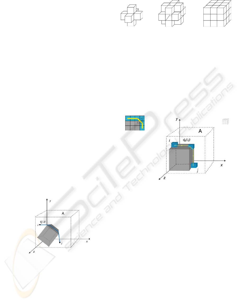
2 3-D GEODESIC DISTANCE
The geodesic distance in three-dimensional sets is a
generalization of the two-dimensional distance.
Geodesy in 3-D brings nothing really new into play,
as it only requires the choice of a digital unit ball of
the structuring element (Serra, 2002). Let i and j be
coordinates in Z3. As such, the geodesic dilation of
size n of i in A corresponds to the geodesic distance
of i in A up to j:
}1,0{
3
: →⊂ Z
f
Df (5)
In Fig. 2, we show the geodesic distance dA (i,j)
between the points i and j in a 3-D structure. We can
observe that the geodesic distance avoids all the
obstacles between the initial and final points.
Figure 2: Geodesic distance in a 3-D setting.
To summarize, in digital Z3, the geodesic
distance function starts from marker i and progresses
according to a connectivity: connectivity 6,
connectivity 12 (cube-octahedron), or connectivity
26, for example, as we can see in Fig. 3.
Figure 3: Different connectivities in 3-D sets.
The real physical movement of the marker object
through the 3-D mask influences the choice of the
connectivity. One consideration to be taken into
account in the calculation of the geodesic distance is
the diagonal movement. Diagonal movements in the
Z3 digital structure cannot be carried out physically,
since collisions with obstacles or edges of the mask
can occur. This can be seen in the example in Fig. 4.
Figure 4: Diagonal movements in connectivity 26.
3 ALGORITHM FOR
CALCULATING THE OPTIMAL
PATH
The optimal path can be obtained from the geodesic
distance. It is obvious that from the 3-D connectivity
defined, different optimal paths can be obtained.
Furthermore, as the wave-front can have many
points, different mechanisms that limit the search
must be taken into account. To avoid collisions with
the environment during movements, connectivity 6
has been defined.
In our algorithm, the structure or 3-D setting
through which the object to be removed must move,
will be defined as the mask. The marker will be the
object situated at the original point. To reduce
calculations, we only compute the geodesic distance
from the centre of the marker. Since we must ensure
that the object can move through the structure, we
VISAPP 2006 - IMAGE FORMATION AND PROCESSING
154

will dilate the 3-D mask with a structuring element
that is equal to the form the of marker. Once the
geodesic distance has been calculated from the
initial to the final points, the marker is redirected
from the final to the initial point through the wave-
front.
There are many different paths with the same
geodesic distance. To create the shortest path, a
process of “Branch-and-bound”, which limits the
search for valid paths, is carried out. From all the
valid paths, the one with the minimum cost is
chosen. Minimum cost is understood as the fewest
changes in directions. As such, in the search process,
paths that surpass a certain threshold of changes in
direction, or which have co-ordinates that have
already been reached by a path of a lower cost, will
be eliminated. Depending on the length of the path
under study, a given threshold of changes in
direction must not be surpassed. Each new path
under construction (from final to origin) is inserted
into a queue in which the priority level corresponds
to the changes of direction up to that moment (e-
path_add(path, priority level)). The first path in the
queue having the lowest priority level is then
extracted from the queue. The algorithm detailed
hereafter in pseudocode is:
•
inputs:
mask3d as 3-D mask
marker3d as 3-D marker
origin as point
final as point
• outputs: path as point vector
• Data structures:
- wave-front as 3-D wave-front
- pix as present co-ordenate
- e-paths as structure of paths
- newpath as array of co-ordenates
• Initialisation:
wave-front ← 3-D geodesic distance
from origin to final
pix ← final point
newpath_add ← final point
e-paths_add ← (newpath,1)
• Path propagation from final to origin in
the wave-front, according to the neighbours
in the valid connectivity of the pix in the
wave-front. The pix is the last co-ordinate
of the optimal path up to the moment.
while (pix<>origin) do
∀
first level of priority p’∈ e-path do
pix ← (e-paths_first(p’))_last)
∀
co-ordenate c’ ∈ Ng(pix)do
newpath_add(c’)
prioritylevel←direction-changes(newpath)
if(prioritylevel) > max-direction-changes
(newpath_long) then
newpath_reject(c’)
else
e-paths_add(newpath, prioritylevel)
end if
done
done
done
• List of optimal paths
if(pix = origin)then
∀
first level of priority p’∈ e-path do
path ← e-path_first(p’)
done
end if
4 EXPERIMENTAL RESULTS
Below, an example of the application of the previous
algorithm for calculating the optimal path to be
followed to remove an object (marker) from the
initial to the final position in a 3-D setting (mask) is
presented. The marker occupies a cubic space
(3x3x3). Inside the mask there are different
obstacles of different sizes. Once the algorithm has
been applied, three different trajectories of the same
cost (4 changes in direction) are obtained. In Figs 5,
6 and 7, different views of the paths follow by the
marker within the mask can be seen, it is represented
by spheres. The initial and final points are indicated
in the figure by 1 and 2, respectively.
Figure 5: View of the path to be followed in a 3-D setting
with obstacles, using a marker of 3x3x3. The initial and
the target points are indicated by 1 and 2 respectively.
CALCULATION OF OPTIMAL TRAJECTORY IN 3-D STRUCTURED ENVIRONMENT BY USING GEODESY AND
MATHEMATICAL MORPHOLOGY
155
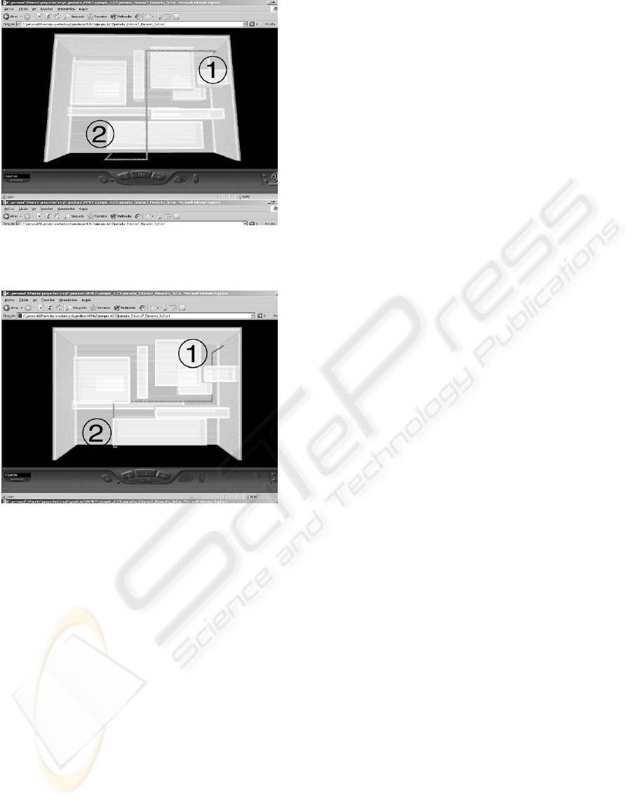
Figure 6: View of second possible path within the same
setting and with the same marker.
Figure 7: View of a third possible path within the same
setting and with the same marker.
5 CONCLUSIONS
In this paper, we have presented a new method for
obtaining the optimal path that an object to be
disassembled in a 3-D structure should follow. The
novelty of this algorithm is that it is based on the
used of the mathematical morphological geodesic
distance. In this case, all of the operations have been
adapted to three-dimensional spaces. The
disassembly algorithm is based on the search for a
path of minimum cost. Cost is considered to be the
number of changes in trajectory required to be able
to remove the object. After having implemented the
algorithm, an example of the application has been
presented. It has been observed that different
solutions of the same cost can be obtained. Having
several different paths for carrying out the
disassembly task by a manipulator, allows us to
choose any of them that the manipulator’s
restrictions permit.
Furthermore, the proposed algorithm allows
navigation within a 3-D setting, considering the
volume of the object to be transported within the
space.
We would like to continue researching in this field,
calculating the optimal path in a dynamic way and
including new information about the setting while
the path is being followed.
ACKNOWLEDGMENTS
This work was funded partially by the following
Spanish MCYT project "DESAURO:
Desensamblado Automático Selectivo para
Reciclado mediante Robots Cooperativos y Sistema
Multisensorial" (DPI2002-02103) and “Ayudas para
Grupos Emergentes (GR03-12)” of the University of
Alicante.
REFERENCES
Belta, C., Kumar, V., 2002. Trajectory design for
formations of robots by kinetic energy shaping. 19th
IEEE International Conference On Robotics and
Automation. pp. 2593-2598.
McAvoy, B., Sangolola, B., Szabad, Z., 2000. Optimal
trajectory generation for redundant planar
manipulators. IEEE Int. Conf. On Systems, Man &
Cybernetics. pp. 3241-3246.
Puente, S.T., Torres, F., Aracil, R., 2003. Non-Destructive
Disasembly Robot Cell for Demanufacturing
Automation. IFAC Workshop on Intelligent Assembly
and Disassembly - IAD'2003. Bucharest, pp. 126-131.
Puente, S.T., 2002. Desensamblado automático no
destructivo para la reutilización de componentes.
Aplicación al desensamblado de PC's. Ph.D. Thesis,
University of Alicante.
Serra, J., 2002. Course on Morphlogical Operators, Centre
de Morphologie Mathématique, Ecole des Mines de
Paris, France.
Tchon, K., Duleba, I., 1993. On inverting singular
kinematics and geodesic trajectory generation for
robot manipulators, Journal of Intelligent & Robotic
Systems, 8 (3) pp. 325-359.
VISAPP 2006 - IMAGE FORMATION AND PROCESSING
156
