
A DETECTION METHOD OF INTERSECTIONS FOR
DETERMINING OVERLAPPING USING ACTIVE VISION
Pablo Gil, Fernando Torres
Department of Physics Engineering Systems and Signal Theory, University of Alicante, Alicante, Spain
Oscar Reinoso
Department of Industrial Systems Engineering, Miguel Hernandez University, Elche, Spain
Keywords: Discontinuities, Overlapping, Occlusion, Occluded partially objects, Structured light.
Abstract: Sometimes, the presence of objects difficult the observation of other neighboring objects. This is because
part of the surface of an object occludes partially the surface of another, increasing the complexitiy in the
recognition process. Therefore, the information which is acquired from scene to describe the objects is often
incomplete and depends a great deal on the view point of the observation. Thus, when any real scene is
observed, the regions and the boundaries which delimit and dissociate objects from others are not perceived
easily. In this paper, a method to discern objects from others, delimiting where the surface of each object
begins and finishes is presented. Really, here, we look for detecting the overlapping and occlusion zones of
two or more objects which interact among each other in a same scene. This is very useful, on the one hand,
to distinguish some objects from others when the features like texture colour and geometric form are not
sufficient to separate them with a segmentation process. On the other hand, it is also important to identify
occluded zones without a previous knowledge of the type of objects which are wished to recognize. The
proposed approach is based on the detection of occluded zones by means of structured light patterns
projected on the object surfaces in a scene. These light patterns determine certain discontinuities of the
beam projections when they hit against the surfaces becoming deformed themselves. So that, such
discontinuities are taken like zones of boundary of occlusion candidate regions.
1 INTRODUCTION
Recognition of objects in image space is not a trivial
problem. Commonly, in robotic environments,
images are taken from scene where several objects
interact together. In addition, the illumination
conditions, view points, positions and orientations of
the objects that are desired to identify can change at
every moment of time.
In this context, the objects in image space suffer
the presence of occlusions and shadows which make
difficult or prevent the recognition due to the
ambiguity of boundary between different object
surfaces, especially when free-form surfaces are
involved in the scene.
To avoid some concrete types of occlusions,
active vision can be adopted. Structured light or
pattern projection systems have been used for this
purpose.
Our method is based on the assumption that the
occlusions are not caused by lack of visibility due to
shadows or by opacity of an object which hides part
of itself due to its geometrical form. Here, we have
assumed that the occlusion is caused by overlapping,
with or without contact. On the one hand, we
consider overlapping with contact when the surface
of an object A is in contact with the surface of
another object B, and the surface of A is partially
hidden by the surface of B. And, on the other hand,
overlapping without contact is considered when the
spatial pose of each object at different depth levels
(different distance from camera used like view
point) cause that the pose of an object A prevents to
perceive another possible B correctly, because B is
in the background of the scene. In these practical
applications, it is the camera and its relative pose
which need to be online adjusted.
The objective of this paper is to find the
intersection zone among surfaces of objects. Such
501
Gil P., Torres F. and Reinoso O. (2006).
A DETECTION METHOD OF INTERSECTIONS FOR DETERMINING OVERLAPPING USING ACTIVE VISION.
In Proceedings of the First International Conference on Computer Vision Theory and Applications, pages 501-507
DOI: 10.5220/0001364905010507
Copyright
c
SciTePress

intersection is caused by surfaces discontinuity
among different objects. Determining this
discontinuity, it is possible know which is the
intersection zone that delimit a possible occlusion
zone of an object hidden by another one.
This paper is organized as follows: The concept
and the types of occlusion are described in section 2,
also in this section we briefly expose the recognition
systems for occluded object presents in the literature
and which is the main problem of each system.
Section 3, show a method based on structured light
to detect occluded zones by overlapping between
objects in the image space. Our approach consists of
two steps. First, we fit the contours of beam
projection in the image with polygonal approach.
Second, it is commented a clustering process to
separate beam projection over different surfaces or
surfaces with different depth level, previously fit as
polygonal contours. The presented clustering
process combines moments and distances. To this
end, our clusters are fit afterwards by means of
straight lines. These one delimits the overlapping
zone. Section 4 gives the experimental results in the
implementation and 5 the conclusions.
2 CONCEPT AND ANALYSIS OF
OCLUSSIONS
The recognition and classification systems of objects
are based generally on the recognition from the
extraction of characteristics and properties of the
visible part of the objects (Bhanu, 2003)(Ulrich,
2001)(Ying, 2002). Therefore, the recognition
systems employed for computer vision do not often
work correctly when there are partially occluded
objects in a scene. This is because different types of
objects can be very similar if its visible part is only
observed (Figure 1).
There are different ways to classify the type of
occlusion. Depending on the cause that produces it,
the following categories can be distinguished:
• Occlusions in which an object covers a portion
of the area of other object which is wished to be
recognized and it is not absolutely visible. It is
well-known like overlapping (Boshra,
2000)(Ying, 2002).
• Occlusions by opacity. An object hides part of
itself due to its own geometry (Bhanu, 2003).
• Occlusions due to shadows. The kind of
illumination causes shadows in the image
around the object to be recognized or around the
rest of present objects in the scene. Thus, an
object can be occluded partially by its own
shadow or the shadow of other object according
to the kind of light employed (Bhanu,
2003)(Ulrich, 2001).
Almost all the recognition systems of occluded
partially objects which obtain good results of
success in the identification, are based on statistical
or stochastics methods and need a great percentage
of probability information (Park, 2003)(Ying, 2002).
Some of the techniques used in these systems
aim at the recognition of flat objects, 2D-objects or
three-dimensional ones (Chan, 2002) (Park,
2003)(Ulrich, 2001)(Ying, 2002) but whose registry
in image space and the processing employed does
not permit to work with the third dimension. In
much of these works, is not important what type of
occlusion appears, why it is caused or how it can be
avoided or corrected or where is located that
occlusion in the image. Only, the bi-dimensional
information of the visible part of the object is
analyzed and studied.
Here, a possible solution to improve the
recognition of objects with occlusions is proposed.
This one consists in determining where the occlusion
is located in image space. Thus, if the occlusion
zone is known, the camera can be repositioned with
respect to a non-planar object given to avoid or
reduce it. Furthermore, additional information about
the boundary and occlusion zones of the objects can
be important for a successful recognition process.
3 DETECTION OF
OVERLAPPING ZONES
In this paper, we have proposed an approach for the
detection of intersection in surfaces. When a light
plane hit different surfaces, that is to say surfaces of
a same object with different orientations or depth
values, or hit surfaces of different objects, a
discontinuity effect is caused in the projection
planes. The discontinuity is caused by the breakage
Figure 1: A same perception for different occluded
objects.
VISAPP 2006 - IMAGE ANALYSIS
502
of light beam projection; thus several projection
planes displaced in the space can be observed.
Our active vision system consist of a light
pattern projector LASIRIS SNF, with a wavelength
of 660nm, a power of 20mW, a fan angle about 15º
and 7 concentric circles with an interbeam angle of
0.77º, and a CCD camera. The intrinsic and extrinsic
parameters of the camera are not necessary to know
them to the overlapping detection, because
reconstruction task are not made. Only, when the
camera is wanted to reposition, both the intrinsic and
extrinsic parameters of the camera are assumed from
the pre-calibration offline.
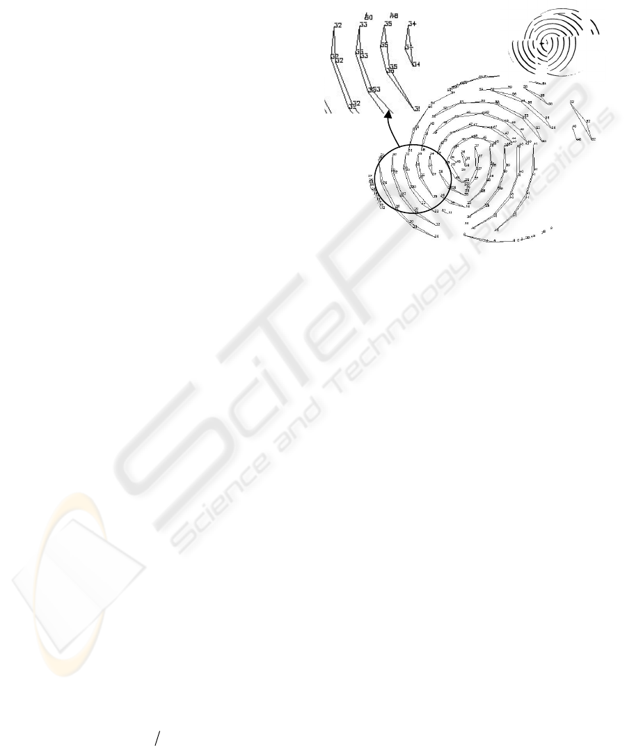
3.1 Approach of Contours
In our work, the first stage consists of extracting the
contours of circle pattern. To do it, firstly, a
Gaussian smoothed process with a 3x3 size mask is
done to reduce the produced noise when the beam
hit too reflecting surfaces. Later, the image is
binarized by means of a suitable threshold,
according to the wavelength of the laser.
Experimentally, a luminance threshold about 70 has
been considered for 660nm. With this threshold it is
possible to extract only the information of contours
from the projected laser pattern.. Next, the projected
circles in the image are detected by means of a
convolution process. In this process, 8-connectivity
masks are used (Teh, 1989). Thus, the pixels which
determine each contour are found. This set of pixels
corresponds to the 2D-points which compose each
projected circle are fit by a polygonal approach.
The advantages of a polygonal approach are, on
the one hand obtaining a simple representation for
each contour which permits a fast and efficient
comparison process between contours. On the other
hand, we have the advantage of the reduction of the
number of interest points detected during the contour
extraction process. Thus, the beam projection is
only represented by a minimum set of interest points
without loss of stability in the contour extraction
process (Figure 2).
Our approach method is based on the Douglas-
Peucker’s algorithm (Douglas, 1973)(Hersberger,
1993). Where, each contour is approximated by a
poly-line, P
s
. If a contour is defined as a sequence of
n points so that
{}
ns
pppC ,...,,
21
= , a poly-line P
s
,
can be defined as the union of 1-degree segments,
where l denotes each segment.
{}{ }
10/)1(
1
1
1
1
1
1
≤≤−+==
+
−
=
+
−
=
tpttpllP
ii
n
i
ii
n
i
s
UU
{}
2...
1
≥= nppP
ns
The adjustment is based on the representation of
set of points by means of edge segments where the
proximity of each point to the edge segment must be
inferior to a tolerance factor
ε
which is taken like
reference threshold. The proximity is measured like
a normal distance vector to each candidate edge
segment.
The algorithm begins approximating all the
points of a same contour,
{}
ns
pppC ,...,,
21
= , with
a poly-line which joins the fist and the last point of
the edge contour,
{}
ns
pplP
11
=
=
. The distance of
each intermediate point to the poly-line is measured,
and the farthest point with a tolerance greater than
the
ε
value, is added to the simplification process
and takes part to build a new poly-line
{
}
nis
pppP
1
=
. Later, this one is divided into two
segments
{
}
i
ppl
11
=
and
{}
ni
ppl =
2
and the union
of both will compose as
{}{ }
nis
pppllP
121
, == .
Thus, these steps are repeated iteratively for each
edge contour until all the points which belong to the
poly-line do not violate the value rank marked by the
tolerance factor. If the distance of an intermediate
point to a poly-line is inferior to the tolerance factor,
this one is not taken into account for the
simplification process of the poly-line. The
polygonal adjustment process has permit to
approximate the laser beam contours in a more
stable way than a set of contour points. Now, each
edge contour is composed by an inferior number of
points. Each contour is a set of points greater than
two which it is the minimum number of points
necessary to define a segment.
Nevertheless, in spite of the previous smoothing
pre-processing, during the contour detection process,
some contours have been approximated by poly-
lines of small length, this polylines are formed by a
Original
contours
Approach
contours
Figure 2: Approach of a beam.
A DETECTION METHOD OF INTERSECTIONS FOR DETERMINING OVERLAPPING USING ACTIVE VISION
503
small number of points. This fact can be due to
noise, contour points which contribute with little
information because it represents very small and
despicable discontinuities. Therefore, the
approximated contours should be filtered in order to
work only with those having some length and are
determined by a number of points greater than three
{}
3...
21
≥= npppP
ns
. Once filtrated, it is
necessary number the candidate contours again with
a new numberation, despising those which are not
useful because they do not contribute with important
discontinuity information or because they can cause
confusion.
3.2 Clustering and approach of
discontinuity
Once, the polygonal approaches have been filtered,
the end points are only chosen. These points are the
tactically important points which will determine the
directions of discontinuity
{}
3
1
≥= nppP
ns
. These
directions of discontinuity are not but the zones of
breakage of the light beam projections, when the
beam hit over two surfaces with different depth or
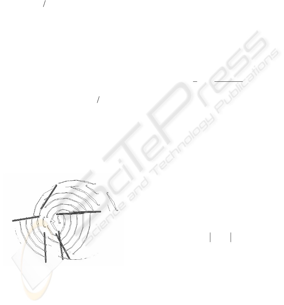
orientation. Later, a method of adjustment of the
tactically important points is applied by means of
straight lines. These straight lines determine the
candidate zones and the suitable direction for the
search of possible discontinuities which are present
in the changes of surface (Figure 3).
A clustering process of tactically important
points is carried out to be able to determine
whichever straight lines are necessary to fit them,
and to discrimante what tactically important points
belong to one or intersection. The clustering process
permits to group the tactically important points
according to two parameters: inertial moments
(Chavez, 1999) and metric distances (Teague, 1980).
Thus, each edge contour approximated by a poly-
line
s
P has two tactically important points, each one
must belong to different clusters, and must have
associated the central moments of the poly-line to
which they belong. The central moments are
invariant to transfering identical beams in the image,
and they do not depend on the position that the beam
projections have in the image.
∫∫
−−= dxdyyxfyyxx
q
c
p
cqp
),()()(
,
μ
Furthermore, it is possible to determine the
rotation of each edge contour around its gravity
centre from the central moments and with the aid of
the components of inertial tensor, as:
2,00,2
1,1
2
arctan
2
1
μμ
μ
θ
−
=
The parameter of inertial moments is employed
to discern between tactically important points which
belong to poly-lines, and therefore to contours with
the same orientation. This way, we have supposed
that the beam projections over the same surface of
an object A have similar inertial moments. Although,
in an object B which is overlapping and occluding
part of surface of A, the inertial moments estimated
from the beam projections over a surface of B, are
different to those estimated from A (Figure 3). When
a discontinuity is detected an orientation change of
the beam projections takes places, and consequently
a new value of the inertial moments.
Also, another parameter to emphasize is the
distance of Minkowski L
2
. Thus, the distance of
each tactically important point to the rest of
tactically important points is calculated, trying to
minimize it.
The distance parameter is used to avoid to group
as points of a same discontinuity, those points which
can agree at inertial moment, but due to their little
proximity they may not belong to the same
candidate zone. For this reason, only the tactically
important points, near among them and whose poly-
lines have similar inertial moments, are clusterized.
Then, we obtain n sets of points of the following
type:
{
}
nisssp
ni
<
<
=
0/...
21
where
{}
n
sss ...
21
are the points nearer
i
p ordered according to
proximity. Finally, the difference of moments for
each set of points is obtained as it was mentioned
above. From the distances and the difference of
r
ji
r
jiL
ppd
r
/1
,
⎟
⎟
⎠
⎞
⎜
⎜
⎝
⎛
−=
∑
Figure 3: Intersection and discontinuity zones among
three objects.
A
B
C
VISAPP 2006 - IMAGE ANALYSIS
504
moments calculated for each set
{}
ni
sssp ...
21
= ,
the clustering process is made. In this way, for any
two points
i
p and
j
s
, these will be able to be
jointly stored and included in the same cluster,
solely if they fulfill that
cij
d
ϕ
θ
< , with
c
ϕ
the
angular tolerance allowed to consider it similar
orientation.
Finally, after the tactically important points have
been grouped by means of the clustering process,
(Figure 4), the candidate zones which represent
discontinuities in the image are defined as those
zones which cotain each cluster. In order to
determine the search direction of those candidate
zones and their boundary, it is necessary to make a
linear adjustment by least-squares method which
calculates the straight line segments which diminish
the Minkowski’s distance L
1
-L
2
of each set of
tactically importan points to the straight line
segment (Figure 3).
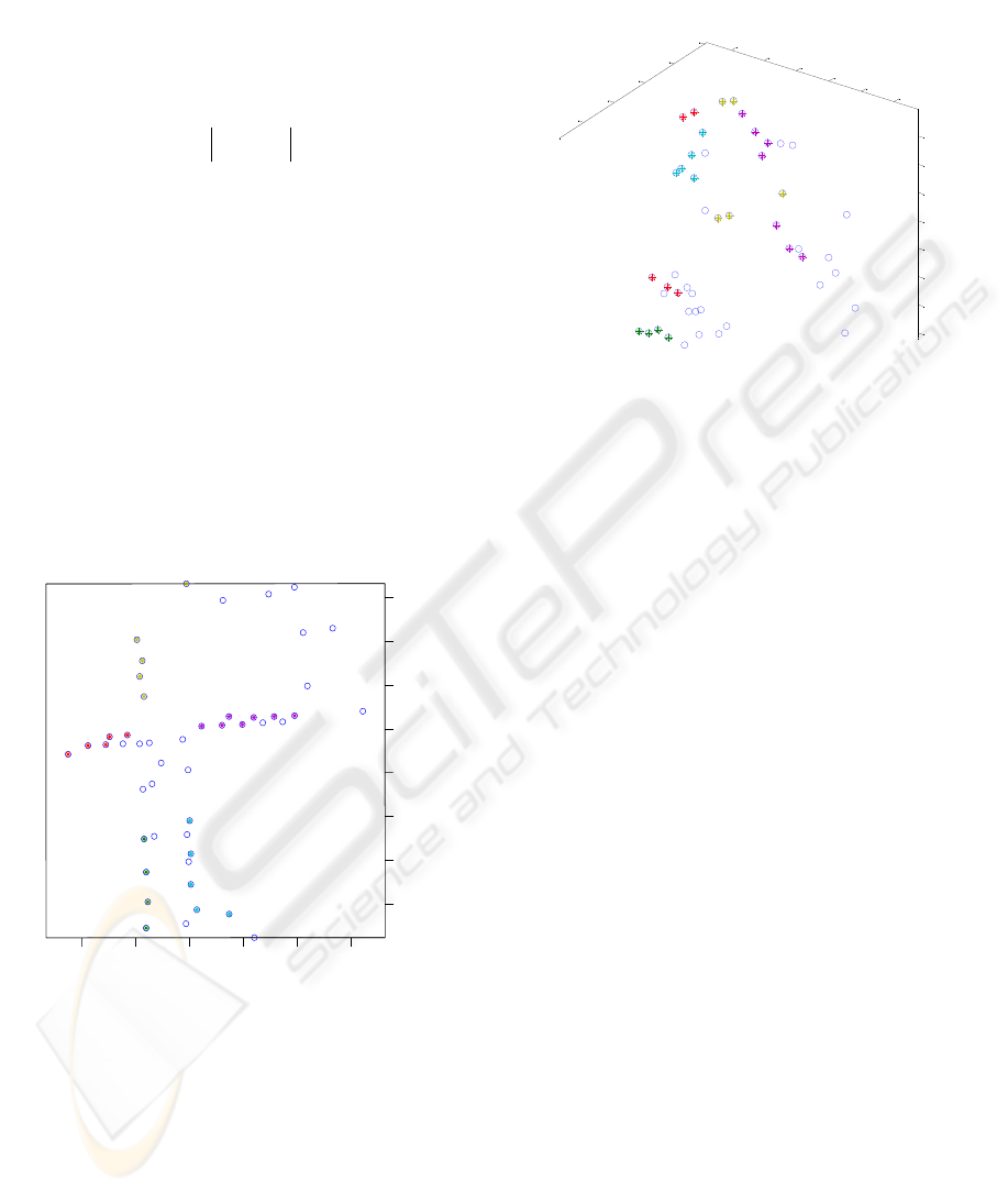
In Figure 4, the clustered sets of points are
represented by different colours.
The 2D-representation shows the relation of
distance among the points of each cluster.
Furthermore, in the distribution space of clusters
shown in Figure 5, it is observed that using jointly
parameters like distances and inertial moments,
points which could be considered very different can
be grouped. Thus, figure 5 shows the relation
between the pose of each point in image space and
its inertial moment.
The coloured points determine the intersection
zones between two objects. Thus, figures 4 and 5
represent the clusters used for the approach shown in
figure 3.
4 EXPERIMENTAL RESULTS
In our experiments, the objects used are
polyhedrons. We have not considered objects with
smooth surfaces. The size of captured image is
768x576 and all images have been acquired with a
monochrome CCD in our laboratory.
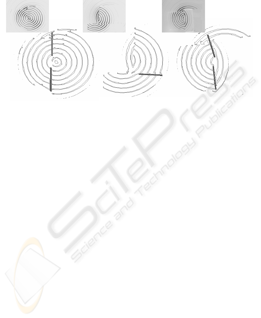
The experimental results exhibit satisfactory
coherence in the spatial detection by discontinuities
when the discontinuities are caused by overlapping
(Figures 6b and 6c). However, the proposed method
works correctly and it is valid when the
discontinuities are caused by contact between sides
of two very near objects (Figure 6a).
Figure 6 shows the application of the proposed
method on the detection of intersections among
objects. In our method, the intersections are well
detected while other type of discontinuities is not
detected because they are not caused by the
intersection between objects. In Figure 6a, two
objects have a side of contact and therefore a
discontinuity is caused by the contact between both.
In Figures 6b, and 6c, there is an overlapping
between both objects. This overlapping is caused
because an object called B is located upon another
one A. Moreover, there is an occlusion because B
hidden part of surface of A. In theses two cases, the
discontinuities caused by overlapping are only
detected.
sjpiij
d
θθθ
−=
200 300
400 500
600 700
15
0
20
0
25
0
30
0
35
0
40
0
45
0
50
0
Figure 4: 2D-Representation of the clustering process.
A
B
C
200
300
400
500
600
700
100
200
300
400
500
-60
-40
-20
0
20
40
60
80
Figure 5: 3D-Representation of the clustering process.
A DETECTION METHOD OF INTERSECTIONS FOR DETERMINING OVERLAPPING USING ACTIVE VISION
505
5 CONCLUSION
In this paper, we studied the occlusion by
overlapping using concentric pattern projections.
The developed method was implemented with
satisfactory experimental results. The system can
work well for detection of simple polyhedral
surfaces without requiring apparent features. In the
practice this system is used jointly with colour
segmentation techniques. This active vision system
is useful for occlusion detection when there are
several objects in the scene with a same colour. In
this case, the colour segmentation techniques fail. In
addition, it is also useful to provide additional
information when they work well, this is when the
objects have colour different. Perhaps, an analysis of
the proposed method could suggest that a method
based on range data analysis could be applied to
obtain discontinuities from depth information of a
more robust way. However the computation of depth
data requires a previous camera calibration, and
therefore a triangulation method to calculate the 3d-
space coordinates. The method proposed permits to
work with cameras with unknown intrinsic and
extrinsic parameters as opposed to the methods
based on range data. In many recognition
applications, in which the camera changes the
localization and focal length, the use of the proposed
method is an advantage because a recalibration of
laser-camera system is not a necessary.
REFERENCES
Bhanu B., Lin Y., 2003. Stochastic models for recognition
of occluded target. Pattern Recognition 36, pp. 2855-
2873.
Boshra M., Ismael M.A., 2000. Recognition of Occluded
Polyhedra from range images. Pattern Recognition
33, pp. 1351-1367.
Chan C.J., Chen S.Y., 2002. Recognizing Partially
Occluded Objects Using Markov Model. International
Journal of Pattern Recognition and Artificial
Intelligence 16(2), pp. 161-191.
Chavez, E., Navarro G., Baeza-Yates R., Marroquín J.,
1999. Searching in metric spaces.
Technical Report TR/DCC-99-3, Dept. of Computer
Science, Univ. of Chile.
Douglas D., Peucker T., 1973. Algorithms for the
reduction of the number points required to represent a
digitized line or its caricature. The Canadian
Cartographer 10(2), pp. 112-122.
Hershberger J., Snoeyink J., 1993. Speeding Up the
Douglas-Peucker Line-Simplification Algorithm.
Proc. 5
th
Symp. On Data Handling, pp. 134-143.
Teague M.R., 1980. Image Análisis via the general theory
of moments. Journal of Optical Society of America
70(8), pp. 920-930.
Teh C.H., Chin R.T., 1989. On the detection of dominant
points on digital curves. IEEE Trans. PAMI 1(8), pp.
859-872.
Park B.G., Lee K.M., Lee S.U., Lee, J.H., 2003.
Recognition of partially occluded objects using
probabilistic ARG (attributed relational graph)-based
matching. Computer Vision and Image
Undesrstanding 90, pp. 217-241.
Figure 6: Results for different pose of o
b
jects (real objects in part superior and image
processed in part inferior).
A B A
B
A
B
a
)
b
)
c)
VISAPP 2006 - IMAGE ANALYSIS
506

Ulrich M., Steger C., 2001. Empirical Performance
Evaluation of Object Recognition Methods. Empirical
Evaluation Methods in Computer Vision. IEEE
Computer Society Press. Los Alamitos, C.A., pp. 62-
76.
Ying Z., Castañon D., 2002. Partially Occluded Object
Recognition Using Statistical Models. International
Journal of Computer Vision 49(1), pp. 57-58.
A DETECTION METHOD OF INTERSECTIONS FOR DETERMINING OVERLAPPING USING ACTIVE VISION
507
