
NiMMiT: A NOTATION FOR MODELING MULTIMODAL
INTERACTION TECHNIQUES
Davy Vanacken, Joan De Boeck, Chris Raymaekers, Karin Coninx
Hasselt University, Expertise Centre for Digital Media and Transnationale Universiteit Limburg
Wetenschapspark 2, BE-3590 Diepenbeek, Belgium
Keywords:
Multimodal Interaction, Interaction Technique, Interactive Virtual Environment, Metaphors, Model-Based De-
sign.
Abstract:
The past few years, multimodal interaction has been gaining importance in virtual environments. Although
multimodality makes interaction with the environment more intuitive and natural, the development cycle of
such an environment is often a long and expensive process. In our overall field of research, we investigate
how model-based design can help shorten this process by designing the application with the use of high-level
diagrams. In this scope, we present ‘NiMMiT’, a graphical notation suitable for expressing multimodal user
interaction. We elaborate on the NiMMiT primitives and illustrate the notation in practice with a comprehen-
sive example.
1 INTRODUCTION AND
RELATED WORK
Designing intuitive and easy to use computer systems
is not always an obvious task. In spite of the extensive
knowledge that exists nowadays, the problem is even
more pronounced when interacting in 3D. Humans in-
teract daily in a (real) 3D world, but it turns out, how-
ever, that moving into a 3D virtual world causes a lot
of usability problems to appear. Over the last years,
several interaction techniques (ITs) have been inves-
tigated in order to overcome those problems, and to
make the interaction more natural. Despite all efforts,
each technique still has its own strengths and weak-
nesses.
We can divide all user tasks in a 3D world in three
classes (Esposito, 1996): Navigation, Object Selec-
tion and Object Manipulation. Well-known naviga-
tion metaphors include Flying Vehicle and Scene In
Hand. Object Selection can, for instance, be done
by a virtual hand or ray selection. Finally, com-
mon object manipulation metaphors include virtual
hand, HOMER and Voodoo Dolls. A comprehen-
sive overview of the most important metaphors can
be found in (De Boeck et al., 2005).
When developing an interactive 3D interface, the
designer has a large number of possibilities: choos-
ing, combining and adapting existing solutions or
even developing a custom-made solution. As the ac-
ceptance of an IT often depends on the concrete appli-
cation setup, and the user’s experience and foreknowl-
edge, the most appropriate way to evaluate a solution
is by testing it in a user experiment. However, test-
ing solutions in practice means that each one must be
implemented separately.
In this paper, we propose a graphical notation
which makes it easy to design and adapt an IT with a
minimum of coding effort. Moving the implementa-
tion of the interaction to a high-level description also
introduces a way to easily reuse previous solutions.
It allows a designer to quickly change between solu-
tions or easily adapt existing solutions according to
the findings of test persons, hence shortening the de-
velopment cycle.
In the next section, we first introduce some exist-
ing notations, each with their particular strengths and
weaknesses. Thereafter, we clarify the requirements
to describe an interaction technique. Subsequently,
we explain the basic primitives of our new notation,
which combines the aforementioned requirements. In
section 3 we explain how the notation can be used for
the automatic execution of an interaction technique
and how it can support quick evaluations. Finally, we
illustrate the notation by means of an example we re-
alized.
224
Vanacken D., De Boeck J., Raymaekers C. and Coninx K. (2006).
NiMMiT: A NOTATION FOR MODELING MULTIMODAL INTERACTION TECHNIQUES.
In Proceedings of the First International Conference on Computer Graphics Theory and Applications, pages 224-231
DOI: 10.5220/0001357902240231
Copyright
c
SciTePress
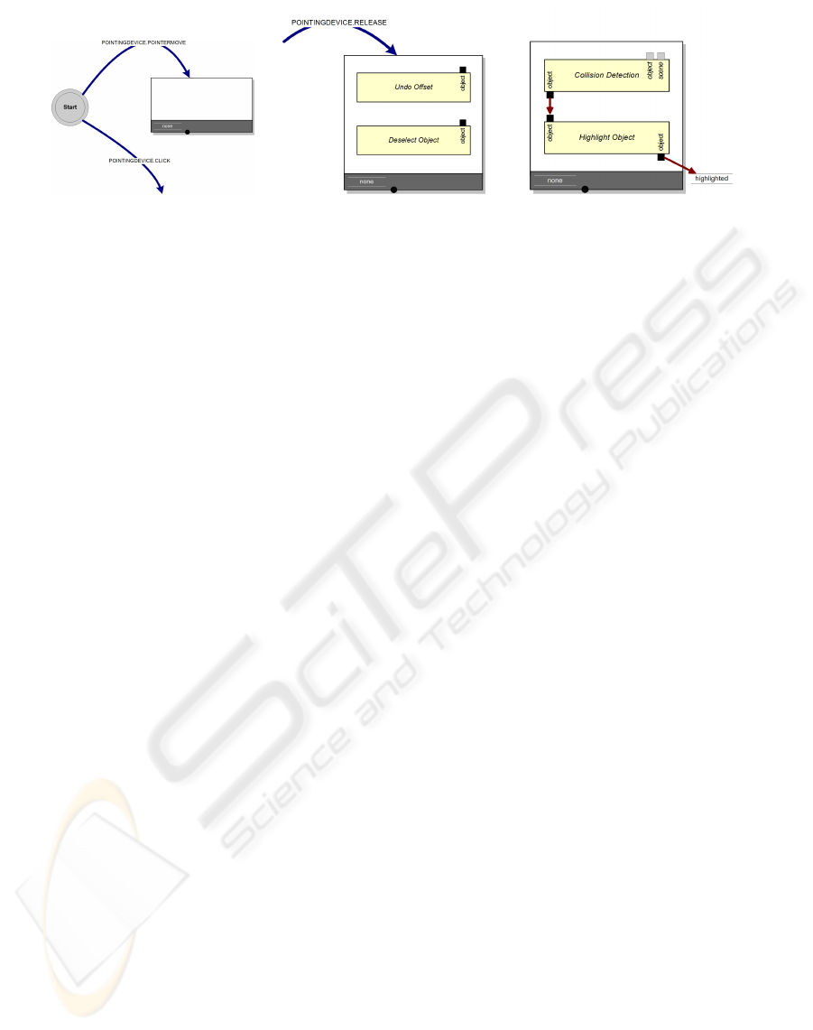
(a) Start state with possible
events.
(b) Task chain. (c) Data flow between tasks
and to a label.
Figure 1: NiMMiT basics.
2 NIMMIT: DESCRIBING
INTERACTION TECHNIQUES
2.1 Background
In literature, quite some interesting research can be
found on modelling ITs. Several authors seem to
agree that states and events are a rather natural way of
describing interaction (Harel, 1987). State charts are
based on the formal mechanisms of finite state ma-
chines and are often used as a foundation for more
extended notations, such as Petri Nets (Palanque and
Bastide, 1994). A basic element of such a notation is
a state transition, which has the general form “when
event a occurs in state A, the system transfers to state
B”. A lot of ITs seem to be state and event driven by
nature. For instance, if an object is selected (state) and
the button is pressed (event), we can start dragging the
object (new state).
Other approaches focus on the data flow during
the interaction. InTml (Figueroa et al., 2002) and
ICon (Dragicevic and Fekete, 2004) are two very sim-
ilar notations, using a data flow architecture. The di-
agrams consist of filters, performing the basic actions
of the interaction. Each filter contains input and out-
put ports: output ports can be connected to input ports
of other filters, and a filter is executed when it re-
ceives a legal value on all of its input ports. Another
data-flow approach can be found in UML 2.0 (Am-
bler, 2004), using activity diagrams. In many ways,
these diagrams can be seen as object-oriented equiva-
lents of flow-charts and data flow diagrams.
Although both approaches clearly have their bene-
fits, to our opinion, none of them offers an ideal solu-
tion to describe user interaction. From a preparatory
study, we found that, while describing a technique us-
ing a state driven notation, the lack of data handling
can be very restricting. Moreover, Petri Nets, for
instance, quickly become very complex, even when
describing a rather simple interaction. Alternatively,
using one of the data flow based notations, complex
structures have to be designed to enable or disable
certain parts of the interaction. Therefore, both ap-
proaches can be seen as complementary.
Based upon these findings, we developed a graph-
ical notation which is both state and data driven, and
supports device abstraction by means of events. This
allows us to maintain data flow, while inheriting the
formalism of state charts, which is necessary for au-
tomatic execution. The notation is called NiMMiT
(Notation for Multimodal Interaction Techniques). To
our opinion, the strengths of this solution are the easy-
to-learn diagrams, which provide an unambiguous de-
scription of the interaction, and can be interpreted by
an application at runtime.
2.2 Requirements for Describing
User Interaction
In this paragraph, we clarify our vision on interaction.
We use a rather abstract approach, which is formu-
lated as a set of requirements, serving as a guiding
principle for the remainder of our work on interaction
modelling.
In our opinion, as a result of our preceding exper-
iments, a notation to describe interaction techniques
must support the following requirements:
• it must be event driven,
• state driven,
• data driven,
• and must support hierarchical reuse.
In the next subsections, we will motivate the impor-
tance of these requirements in the context of interac-
tion techniques.
2.2.1 Event Driven
Interaction techniques are inherently driven by user-
initiated actions, which we define as events. Since
NiMMiT: A NOTATION FOR MODELING MULTIMODAL INTERACTION TECHNIQUES
225

(a) State transition. (b) Conditional state transition.
Figure 2: State transition and conditional state transition.
human interaction is multimodal by nature, it can
be seen as a combination of unimodal events (e.g.
pointer movement, click, speech command, gesture,
etc.). An event has the following properties:
• a source, indicating the modality and/or the abstract
device that caused it (speech, pointing device, ges-
ture, etc.),
• an identification, defining the event itself (e.g. but-
ton click, a certain speech recognition, etc.),
• a list of parameters, giving additional information
about the event (such as the pointer position).
Events can be seen as “the initiators” of the different
parts of the interaction.
2.2.2 State Driven
While interacting with it, the system not always has
to respond to all available events. Most of the time,
certain events must have occurred before other events
are enabled. For instance, the user first needs to click
the pointer’s button, before being able to drag an ob-
ject. Therefore, we perceive an interaction technique
as a finite state machine, in which each state defines
to which events the system will respond. The occur-
rence of an event also initiates a state transition. In
our example, the dragging technique consists of two
states. In a first state, the IT waits for a click, before
moving to the second state. The second state responds
to the movements of the pointer and executes a state
transition to itself.
2.2.3 Data Driven
Limiting our vision on interaction techniques solely
to a finite state machine would be too restrictive. Af-
ter analysing several existing interaction techniques
in 3D environments, it became clear that throughout
the execution of an interaction some important data
flow takes place. For instance, the user can select an
object and drag it around in a later phase of the in-
teraction. Obviously, certain data must be passed on
as a parameter between the different tasks of the in-
teraction technique. Therefore, a notation to describe
interaction techniques should also support data flow.
2.2.4 Hierarchical Reuse
Some subtasks of interaction techniques recur rather
frequently. Selecting objects is an example of a very
common component. When modelling a new interac-
tion technique, the designer should be able to reuse
descriptions that were created earlier. That way, re-
curring components do not have to be modelled re-
peatedly. In other words, the notation should sup-
port a hierarchical build-up, so an existing diagram
of an interaction technique can be reused as a sub-
task of a new description. Using hierarchical building
blocks contributes significantly to more efficient de-
velopment.
2.3 NiMMiT Basics
States and events. Since the NiMMiT notation is
state and event driven, a diagram can basically be
seen as a state chart. When an interaction technique
is started, it is initiated in the start-state. This state
responds to a limited set of events, such as a speech
recognition, a movement of the virtual pointer, a but-
ton click, etc.
Events are generated by devices. Dependent on
the properties of a physical device, we create an ab-
straction by defining ‘families’. Devices within the
same family generate interchangeable events. Since
we support several families of devices, multimodal-
ity can be accomplished using combinations of events
from different families. The recognition of an event
causes a task chain to be fired (fig 1(a)).
Task chain and tasks. A task chain is a strictly
linear succession of tasks. Figure 1(b) shows a task
chain (big white rectangle with grey border) contain-
GRAPP 2006 - COMPUTER GRAPHICS THEORY AND APPLICATIONS
226
ing two tasks (small shaded rectangles). The next task
in the chain is executed if and only if the previous task
has been completed successfully. The set of possible
tasks obviously depends on the application domain,
but in each particular case, the most common tasks
will be predefined by the system. Clearly, not all task
can be predefined. Therefore, we provide the possi-
bility for the designer to add custom tasks by means
of scripting.
Data flow, data types and labels. In a task-chain,
tasks can pass data from one to another. Therefore,
each task has input and output ports. An output port
of a preceding task is often connected to the input
port of the next task. Input ports can be required or
optional; if a required input port receives an invalid
value, the entire task chain is rolled back. The shape
of the port indicates its data type, and only ports of
the same data type can be linked to each other. To
share data between tasks in different task chains, or to
store data to reuse later, we provide high-level vari-
ables in the form of labels (fig 1(c)). The content of
a label is maintained as long as the NiMMiT diagram
is operational; its scope is the entire diagram.
State transition and conditional state transition.
After a task chain has been successfully executed, a
state transition takes place, which is represented by
the grey arrow in figure 2(a). The interaction tech-
nique goes either to a new state or back to the current
state (a loop). In a new state, the IT may respond
to another set of events. A task chain can have mul-
tiple state transitions associated with it; the value of
the chain’s label indicates which transition should be
executed. Figure 2(b) shows a task chain with a label
‘ID’ and three possible state transitions.
Hierarchical use and input/output parameters.
Since interaction techniques have an interface simi-
lar to the atomic tasks in a task chain, an interaction
technique can be used as a task in a task chain. When
a hierarchical interaction technique is activated, the
current execution is temporarily suspended and saved
on a stack, waiting for the new interaction technique
to finish.
3 AUTOMATIC EXECUTION OF
A MODEL
As described in the previous section, NiMMiT can
be used to unambiguously visualize an interaction
metaphor. It is beyond the scope of this paper to ex-
plain the overall model-based approach for VE devel-
opment (Cuppens et al., 2005) in which NiMMiT fits.
When the notation is used to evaluate and adapt in-
teraction techniques during the development phase,
clearly automatic ‘interpretation’ and ‘execution’ of
the diagrams are required. In the next sections, we
will elaborate on some important aspects of the cur-
rent implementation of the NiMMiT interpreter.
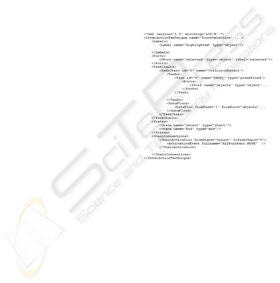
3.1 NiMMiT Framework and XML
First, the graphical notation must be ‘translated’ to
a format which can be efficiently parsed, in order
to allow a framework to perform the execution of
the interaction. Therefore, a NiMMiT diagram is al-
ways saved in a NiMMiT-XML structure. This for-
mat stores all primitives (States, Chains, Tasks, etc)
in a structured way. Figure 3 shows an example of a
simple interaction technique.
Figure 3: NiMMiT-XML of a simple IT.
This XML is easy to parse and can be loaded into
the NiMMiT framework. There, a central manager
maintains the state, listens to events coming from the
application, executes task-chains, and keeps track of
the labels. We designed the NiMMiT Framework in
such a manner that it can operate apart from our ex-
isting research framework, so it can also be applied in
other frameworks or applications.
3.2 Tasks, Custom Tasks and
Scripting
The main actions of an IT are clearly situated in the
tasks. Dependent on the framework and the applica-
tion domain, different sets of tasks are possible. In
our implementation, which focusses on interaction in
3D environments, we provide several predefined tasks
such as ‘selecting’, ‘moving’ and ‘deleting’ objects,
NiMMiT: A NOTATION FOR MODELING MULTIMODAL INTERACTION TECHNIQUES
227
‘collision detection’, etc. When a different task is re-
quired, a custom task can be created. Custom tasks
are coded using a scripting language, which is inter-
preted or compiled at runtime.
3.3 Events and Device Abstraction
Clearly, interaction is initiated by the user, who
communicates with the environment through de-
vices. Since the number of different device setups is
huge, NiMMiT makes an abstraction of these devices
through the use of events: according to the kind of
device which generates an event, events and devices
are grouped in ‘families’, sharing the same properties.
We define pointer and navigation devices, speech and
gesture recognition and user interface elements such
as menus and dialogs. By switching between devices
within the same family, theoretically, the interaction
itself is not affected, and hence, as a result of this ab-
straction, the diagram does not need to be changed
either. On the other hand, when a click-event is for in-
stance replaced by a speech command, the interaction
changes and a small change to the diagram (changing
the event arrow) is required.
4 CASE STUDY
In this section, we explain our notation by means of a
practical example. First, we describe the principles of
the ‘Object-In-Hand Metaphor’, the two-handed in-
teraction technique in our example. Next, we elab-
orate upon the diagrams. We start with the inter-
action technique for selecting an object. The result
will be hierarchically used in the diagram of the non-
dominant hand’s interaction. In the fourth section, the
relation to the manipulation with the dominant hand is
shortly described. Finally, we consider the support for
other types of multimodal interaction.
4.1 The Object-In-Hand Metaphor
As a case study, we have chosen to elaborate on the
Object-In-Hand metaphor, which we presented and
evaluated in (De Boeck et al., 2004). After an ob-
ject has been selected, the user can ‘grab’ the object
by bringing the fist of the non-dominant hand close
to the pointing device in the dominant hand. At that
instant, the selected object moves to the centre of the
screen, where it can be manipulated by the dominant
hand (figure 5). In our implementation, we allow the
user to select the object’s faces and change their tex-
ture. Since the Object-In-Hand metaphor requires the
user to utilize both hands, this example also illustrates
a synchronization mechanism between different inter-
action techniques.
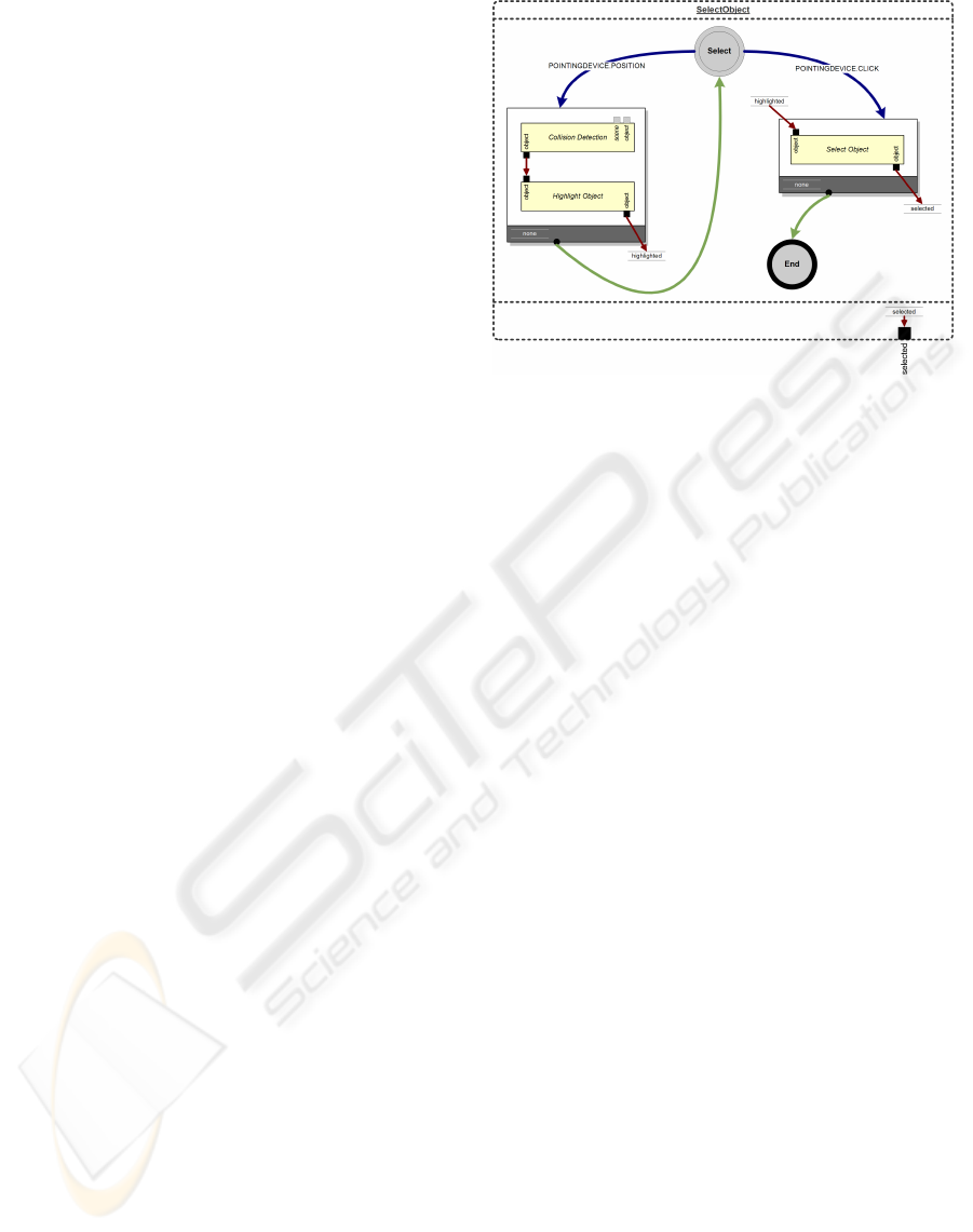
Figure 4: Selecting an object.
4.2 Selecting an Object
As a first step, the user is required to select an ob-
ject. A number of selection metaphors exist, so the
designer has several alternatives. We have chosen a
virtual hand metaphor: highlight the object by touch-
ing it, and confirm the selection by clicking. This
interaction component can be easily expressed in the
NiMMiT notation, as depicted in figure 4.
The interaction technique starts in the state ‘Se-
lect’, which reacts to two events: a movement of the
pointer and a button click. Each time the pointer
moves (and the button is not clicked), the leftmost
task chain is executed. This chain contains two con-
secutive, predefined tasks: collision detection and
highlighting an object. The first task has two optional
input ports, indicating which objects should be taken
into account when checking for collisions. If optional
inputs have no connections, default values are used.
By default, the first task checks for collisions between
the pointer and all the objects in the virtual environ-
ment. If a collision occurs, the colliding object is
passed on via the output port.
The second task in the chain, the highlighting of an
object, will only be executed when all of its required
input ports receive a viable value. If the first task does
not detect a collision, this prerequisite is not satisfied
and the chain is aborted. Consequently, the system re-
turns to the state ‘Select’ and awaits new events. If the
highlighting task does receive an appropriate value,
the object is highlighted. Finally, the output is stored
in the label ‘highlighted’ and a task transition returns
the system to the state ‘Select’.
If a click event occurs while the system is waiting
in the state ‘Select’, the second task chain is executed.
It contains only one task: the selection of an object. If
GRAPP 2006 - COMPUTER GRAPHICS THEORY AND APPLICATIONS
228
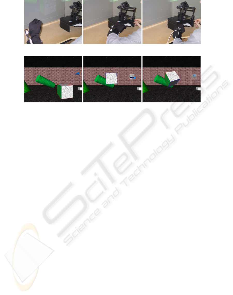
(a) Grabbed object. (b) Hand brought close. (c) Hand rotated.
(d) Selected object. (e) Object-in-Hand. (f) Rotated object.
Figure 5: Object-in-Hand metaphor.
the previous chain successfully highlighted an object,
the task selects that object, which is passed on to the
filter by connecting the label ’highlighted’ to the input
port. The task also stores the selected object in a new
label, ‘selected’. If the label ‘highlighted’ contains
no viable value (e.g., no object was highlighted), the
chain is aborted and the system returns to the state
‘Select’.
If the second task chain finishes successfully, a fi-
nal state transition occurs. The system goes to the end
state and the selected object is outputted via the label
‘selected’. At this moment, the interaction technique
is finished. In the next section, we demonstrate how
this entire diagram can be reused as a single, hierar-
chical task.
4.3 Non-dominant Hand Interaction
After an object has been selected using the afore-
mentioned selection technique, the object can be
‘grabbed’ with the non-dominant hand. By bringing
the fist close to the dominant hand, the selected ob-
ject moves to the centre of the screen, where it can be
manipulated by the dominant hand.
Running the diagram in figure 6 activates the start
state. If an ‘idle’ event occurs, which happens contin-
uously when no other events are generated, the first
task chain is executed. The only task in this chain is
our previously defined selection technique. As long
as this task is active, the execution of the current in-
teraction technique is suspended. We store the result
of the selection, the selected object, in the label ‘se-
lected’. Next, a state transition to ‘Prepare OiH’ is
performed.
This state waits for either a gesture or a cancel
event. The gesture is defined as ‘a closed non-
dominant hand brought in the proximity of the dom-
inant hand’. When this event takes place, the second
task chain is fired. The first task in this chain is a
scripting task, which calculates a custom offset be-
tween the virtual position of the non-dominant hand
and the centre of the world. The task requires the se-
lected object as an input. The output is the original
position of the selected object, the offset and the new
position. All these outputs are stored in labels. The
next task moves the selected object to the given posi-
tion, and the last task simply sets a label to true. This
label is needed for the synchronization, which will be
explained in section 4.4.
Eventually, the system ends up in the state ‘OiH’
and looks for one of the awaited events. When the
user opens his/her hand (recognized as a gesture), a
transition (without task chain) to the state ‘suspend
OiH’ takes place. If the hand is closed, the ‘OiH’-
state is reactivated. These state transitions imple-
ment clutching and declutching, in order to rotate an
object beyond the physical constraints of the user’s
arm. ‘OiH’ also responds to movements of the non-
dominant hand. In the corresponding task chain, a
new position is calculated according to the move-
ments of the hand, and the object is moved. Finally,
both states respond to a ‘cancel’ event and the with-
drawing of the non-dominant hand (a gesture). In
both cases, the activated task chain restores the ob-
jects original position and resets the ‘isRunning’ label
to false.
NiMMiT: A NOTATION FOR MODELING MULTIMODAL INTERACTION TECHNIQUES
229
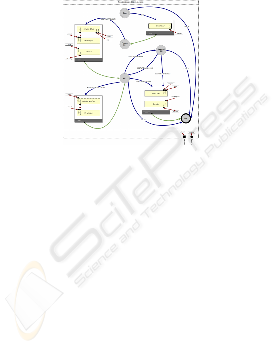
Figure 6: The interaction of the non-dominant hand.
4.4 Collaboration with the Dominant
Hand
If the ‘OiH’-state of the ‘Non-dominant Object-in-
Hand’ diagram has been reached, the label isRunning
is true. This value is sent to the output port of the in-
teraction technique. The interaction of the dominant
hand, which is another NiMMiT diagram, depends on
the state of the diagram of the non-dominant hand:
when the non-dominant hand is not in the proximity
of the dominant hand, it has no sense to enable the
execution of the dominant hand’s interaction. There-
fore, the isRunning output label is connected as an
input label to this latter diagram. Based on the value
of this label, the execution can be controlled.
4.5 Considerations on Multimodality
As formulated in the previous paragraphs, the nota-
tion is designed to support multimodal interaction.
The example shows how direct manipulation, gestures
and menu commands can cooperate, but more ad-
vanced multimodal interaction is also possible. Based
on the idea that a multimodal interaction is caused
by several unimodal events, the notation provides the
opportunity to support sequentially multimodal and
simultaneous multimodal interaction (Sturm et al.,
2002), as well as equivalence between the modalities
(Nigay and Coutaz, 1997). Sequential multimodal-
ity can be implemented by defining subsequent states
that respond to events coming from different sources.
First, in figure 7(a), an object is moved via a gesture.
In the next state, it is deselected by speech. Simulta-
neous multimodality is supported by using the AND-
operator between the affecting events: the object is
moved by a pointer device movement, together with
a speech command as shown in figure 7(b). Finally,
equivalent modalities are carried out using the OR-
operator. Figure 7(c) illustrates a move command that
can be achieved by either a speech-command or a ges-
ture.
5 CONCLUSIONS AND
ONGOING WORK
This paper described NiMMiT, a graphical notation
to model user interaction in 3D environments, which
has been developed in our lab. The notation, based
on both state driven and data driven primitives, al-
lows a designer to express interaction techniques in
a visual way. We have illustrated the expressiveness
of NiMMiT by applying the notation to the ‘Object-
In-Hand’-metaphor. Currently, the implementation of
the runtime interpretation engine has been fully com-
pleted and tested with some well known interaction
techniques other than described in this paper. Fur-
ther research is planned to demonstrate the usabil-
ity/usefullness of the notation. We also want to inte-
grate NiMMiT in other frameworks in order to prove
GRAPP 2006 - COMPUTER GRAPHICS THEORY AND APPLICATIONS
230
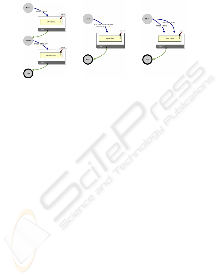
(a) Sequential MM. (b) Simultaneous MM. (c) Equivalence.
Figure 7: Multimodal support within NiMMiT.
the generality of our solution. Furthermore, the nota-
tion is not only intended to express interaction tech-
niques, but it is also designed to allow an unambigu-
ous modelling of the interaction technique, which can
facilitate the (often tedious) development process of
usable interactive VEs. This is established by allow-
ing a designer to efficiently test, change and adapt the
interaction based upon the pilot user tests, as well as
by reusing previously generated diagrams.
ACKNOWLEDGEMENTS
Part of the research at the Expertise Centre for Digi-
tal Media is funded by the ERDF (European Regional
Development Fund), the Flemish Government and
the Flemish Interdisciplinary institute for Broadband
Technology (IBBT). The VR-DeMo project (IWT
030284) is directly funded by the IWT, a Flemish sub-
sidy organization.
The authors also want to thank Erwin Cuppens for
his valuable contribution to the implementation.
REFERENCES
Ambler, S. (2004). Object Primer, The Agile Model-Driven
Development with UML 2.0. Cambridge University
Press.
Cuppens, E., Raymaekers, C., and Coninx, K. (2005). A
model-based design process for interactive virtual en-
vironments. In Proceedings of 12th International
Workshop on Design, Specification and Verification
of Interactive Systems (DSVIS’05), pages 239–250,
Newcastle upon Tyne, UK.
De Boeck, J., Cuppens, E., De Weyer, T., Raymaekers,
C., and Coninx, K. (2004). Multisensory interac-
tion metaphors with haptics and proprioception in vir-
tual environments. In Proceedings of the third ACM
Nordic Conference on Human-Computer Interaction
(NordiCHI 2004), Tampere, FI.
De Boeck, J., Raymaekers, C., and Coninx, K. (2005). Are
existing metaphors in virtual environments suitable
for haptic interaction. In Proceedings of 7th Inter-
national Conference on Virtual Reality (VRIC 2005),
pages 261–268, Laval, France.
Dragicevic, P. and Fekete, J.-D. (2004). Support for input
adaptability in the ICON toolkit. In Proceedings of the
6th international conference on multimodal interfaces
(ICMI04), pages 212–219, State College, PA, USA.
Esposito, C. (1996). User interfaces for virtual reality
systems. In Human Factors in Computing Systems,
CHI96 Conference Turorial Notes.
Figueroa, P., Green, M., and Hoover, H. (2002). InTml: A
description language for VR applications. In Proceed-
ings of Web3D’02, Arizona, USA.
Harel, D. (1987). Statecharts: A visual formalism for com-
plex systems. In Science of Computer Programming,
volume 8, pages 231–274.
Nigay, L. and Coutaz, J. (1997). Intelligence and Multi-
modality in Multimedia Interfaces: Research and Ap-
plications, chapter Multifeature Systems: The CARE
Properties and Their Impact on Software Design.
AAAI Press.
Palanque, P. and Bastide, R. (1994). Petri net based design
of user-driven interfaces using the interactive cooper-
ative objects formalism. In Interactive Systems: De-
sign, Specification, and Verification, pages 383–400.
Springer-Verlag.
Sturm, J., Bakx, I., Cranen, B., Terken, J., and Wang, F.
(2002). The effect of prolonged use on multimodal in-
teraction. In Proceedings of ISCA Workshop on Mul-
timodal Interaction in Mobile Environments, Kloster
Irsee, Germany.
NiMMiT: A NOTATION FOR MODELING MULTIMODAL INTERACTION TECHNIQUES
231
