
COLLABORATION ON SCENE GRAPH BASED 3D DATA
Lorenz Ammon and Hanspeter Bieri
Institute of Computer Science and Applied Mathematics, University of Bern
Neubr
¨
uckstrasse 10, 3012 Bern, Switzerland
Keywords:
Collaboration, DCC (digital content creation), attributed scene graph, automatic merging, conflict resolution.
Abstract:
Professional 3D digital content creation tools, like Alias Maya or discreet 3ds max, offer only limited support
for a team of artists to work on a 3D model collaboratively. We present a scene graph repository system
that enables fine-grained collaboration on scenes built using standard 3D DCC tools by applying the concept
of collaborative versions to a general attributed scene graph. Artists can work on the same scene in parallel
without locking out each other. The artists’ changes to a scene are regularly merged to ensure that all artists
can see each others progress and collaborate on current data. We introduce the concept of indirect changes and
indirect conflicts to systematically inspect the effects that collaborative changes have on a scene. Inspecting
indirect conflicts helps maintaining scene consistency by systematically looking for inconsistencies at the right
places.
1 INTRODUCTION
3D modeling can be a challenging task, and usu-
ally several specialized artists have to work collab-
oratively on different aspects of the same 3D scene.
Especially if content creation is an evolutionary team
process, as it is often the case in highly creative envi-
ronments, a rather immediate collaboration on a scene
is essential. Also, sometimes a scene gets too large
for one single artist to finish it in time and several
people have to work on it in parallel (e.g. large seam-
less worlds are one of the challenges in content cre-
ation for next generation console games). Quite often
a scene does not evolve just linearly, i.e. alternative
designs are considered, refined, rejected and finally
taken over.
Unfortunately, today’s professional 3D digital con-
tent creation tools (DCC tools), like Alias Maya or
discreet 3ds max, offer only limited support for a team
of artists to work on a 3D model collaboratively. Usu-
ally they store 3D scenes in a simple file, and the
file system’s locking mechanism is applied, so only
one artist can work on a scene file at a time. A
work around for this locking problem are reference
files. Reference files allow the decomposition of a
scene into several parts. A main scene file then ref-
erences all part scene files. Artists can work in par-
allel on separate reference files, but the decomposi-
tion of the scene into parts also puts barriers to the
artists’ collaborative work. In order to see what the
others are doing, an artist has to open the main scene
file or explicitly reference the corresponding part files.
Changes to a scene are coordinated using the main
scene file, but to make the necessary adjustments the
artist always has to find and open the corresponding
part file. Therefore reference files only make possi-
ble a coarse-grained collaboration on rather statically
defined parts of a scene. In addition, managing the
separately evolving parts can get quite cumbersome,
as more parts and especially lots of revisions of them
are created.
Exactly this problem is attacked by Alienbrain Stu-
dio (Alienbrain, 2005) which is today’s leading digi-
tal asset management solution in content creation for
video games. It stores scenes in a central repository,
manages their revisions and is aware of the reference
file mechanism. But it does not provide support for
two artists to work in parallel on the same scene file
and for merging their changes. This support is only
provided for text documents (e.g. program code).
Text files are merged using a standard line-based diff
and merge approach. Such line-based merging does
not work for scene files because it would invalidate
their usually complex internal structure. There ex-
ist approaches in software development (Magnusson
et al., 1993) to make use of the structure of programs
within text files to implement versioning at the finer-
grained level of functions, i.e. not just at the file level.
Yet such approaches do not translate directly to 3D
scenes because program code is inherently text- and
line-based while scenes of standard DCC tools usu-
ally are coded in a proprietary binary format.
The graphics database system GSCOPE (Collison
and Bieri, 2000) implements versioning at the scene
259
Ammon L. and Bieri H. (2006).
COLLABORATION ON SCENE GRAPH BASED 3D DATA.
In Proceedings of the First International Conference on Computer Graphics Theory and Applications, pages 259-266
DOI: 10.5220/0001357602590266
Copyright
c
SciTePress
graph object level. But it focusses on reuse of 3D
models rather than on collaboration on them. There is
no support for the merging of changes that different
artists have made to a scene in parallel. Another ap-
proach to add versioning support to CAD/CASE data-
bases (Wieczerzycki and Rykowski, 1994) extends
the database version approach by a merge transac-
tion that merges database versions by object compar-
ison. But it focusses rather on extending the version-
ing model and does neither really detail scene graph
and change representations nor conflict resolution and
scene consistency.
There exist systems, like Scene-Graph-As-Bus
(Zeleznik et al., 2000), blue-c (Naef et al., 2003),
Mu3D (Galli and Luo, 2000) and Distributed Open
Inventor (Hesina et al., 1999), that directly operate on
the internal structure of a scene to implement a fine-
grained and immediate kind of collaboration. These
systems provide a single distributed scene graph that
usually is replicated on each collaborator’s system.
Changes made to the scene graph by one collabora-
tor are immediately propagated to the replicated scene
graphs of the other collaborators. Objects worked on
by one collaborator are locked for all other collabora-
tors to ensure scene consistency. Because collabora-
tors always share the same instance of the distributed
scene graph, such systems do not have to implement
the merging of scene graphs.
Distributed scene graph systems usually form the
basis for collaboration in virtual reality environments.
But they are not well suited for enabling collabora-
tion between users of standard DCC tools, because
such tools use their own proprietary scene graphs that
were not designed to get distributed. Also their scene
graph APIs tend to hide internal structures and were
not meant to support efficient scene graph replication
and synchronization. In addition, distributed scene
graph systems need all collaborators to be connected
by a common high speed network.
Because there exists always only one instance of
the distributed scene graph, collaboration is immedi-
ate. Artists are not able to privately evaluate different
experimental designs before making an initial version
of their design known to the other artists. Therefore
some collaborators possibly base their work on a de-
sign that might still change heavily.
In the following sections we shall present a system
that supports fine-grained collaboration on scenes of
standard 3D DCC tools. It enables collaboration on
the scene graph at the object level, as opposed to the
coarse reference file level. Several artists can work on
the same scene in parallel without locking out each
other. Because of that, dynamic work assignments
become possible. The artists’ changes to a scene
are regularly merged to make sure that all artists can
see each other’s progress and collaborate on current
data. Artists may work privately on a scene and make
their results public only when they are really ready.
Merging is carried out automatically if there arise no
conflicts between the artists’ different changes to the
scene. In addition, we present a number of strate-
gies for automatic conflict resolution. The effects that
local changes may have on a scene as a whole are
tracked, and possible consistency problems caused by
side effects of these changes are registered as indirect
conflicts and are brought to the artists’ attention. We
give a practical example for the collaboration made
possible among artists by our system by discussing
its application to the development of a 3D model of
the old part of the city of Bern. Finally, we list some
conclusions.
2 COLLABORATIVE VERSIONS
To enable several artists to work collaboratively on a
single 3D scene, we adopt the concept of collabora-
tive versions which is widely and successfully used in
software development. We only give a short overview
here and then concentrate on the critical points when
applying this concept to enable collaboration on scene
graph based data created by common 3D DCC tools.
Key elements of our concept are a repository for stor-
ing scenes, the versioning of scenes, and the auto-
matic merging of scenes.
SS
A
working copy
of artist A
S
B
working copy
of artist B
repository
check-out check-out
check-in
merge
S
A
B
S
1
S
B
check-in
S
1
S
2
DCC toolDCC tool
Figure 1: Collaborative versions.
Figure 1 illustrates how two artists A and B work
in parallel on a scene S. Artist A starts working on
S by checking-out the scene from the repository to a
private local working copy S
A
on his
∗
system. This
check-out operation does not put a lock on the scene
S. Therefore artist B is also allowed to check-out the
scene S from the repository to a local working copy
S
B
on his system, and the same holds for any other
artist. Both artists now make changes to their local
∗
Here and in the following “he” stands also for “she”.
GRAPP 2006 - COMPUTER GRAPHICS THEORY AND APPLICATIONS
260
working copies of the scene using a standard DCC
tool. When artist A finishes his work or a consistent
piece of it, he wants to make his changes to S avail-
able to the other artists. To do so he simply checks
his local working copy back into the repository. The
repository registers the changes artist A made to S
and stores his scene as the new current version S
1
of
S. In the meantime, artist B is also satisfied with the
changes he made to S and wants to make them public
by checking his private working copy back into the
repository. Of course, the current version of S is no
longer the version artist B checked-out, but equal to
the version S
1
which artist A recently checked-in. In
order not to get lost, the changes artist A made to S
must be merged with the changes artist B wants to
check-in. The result is the now current version S
2
of the scene. If both artists made changes to differ-
ent parts of the scene, these changes can usually be
merged automatically. If there arise conflicts, they
must be resolved either automatically by the reposi-
tory or manually by the artists involved. Even if some
changes by artist B were dropped during conflict res-
olution, they would not be lost, because before the
merging takes place, artist B’s working copy S
B
is
checked-in to the repository as an alternative version
S
B
1
to what artist A checked-in earlier. So the whole
work of artist B can be reviewed again at any time if
necessary.
Obviously the merging of different scene versions
is the critical point of the concept of collaborative ver-
sions. Standard revision control systems, like CVS,
ClearCase, Perforce, etc., are not able to automati-
cally merge 3D scene files because they are special-
ized in line-based diff and merge of text files and can-
not handle the usually proprietary binary formats of
3D scene files. Such tools can detect bitwise changes
but do not know how to interpret them and thus are not
able to merge such changes to form a valid 3D scene
again. Therefore, to implement the concept of collab-
orative versions, a repository must know the internal
structure of scenes and be able to interpret the changes
that are applied to them. Fortunately, 3D DCC tools
share an important common concept for managing
scene data, i.e. the scene graph. That allows us to de-
velop a repository system enabling collaboration on
scenes originating not only from one special 3D DCC
tool, but also on scenes coming from the other tools.
What is needed is a general scene graph model being
able to hold the scene graphs coming from the differ-
ent 3D DCC tools.
3 ATTRIBUTED SCENE GRAPHS
Text books usually define scene graphs to be directed
acyclic graphs (DAG) that model the composition
and transformation hierarchy of a scene. However,
3D DCC tools normally use a more sophisticated
kind of scene graph, as a careful analysis of Alias
Maya, discreet 3ds max, Softimage XSI, Open Per-
former, VRML, X3D, Java 3D, OpenSG and Open
Scene Graph shows. Usually there is a DAG part
that models hierarchical relationships between scene
graph nodes, but in addition there exist also many
other relationships between nodes which usually ex-
press some kinds of constraints that do not explicitly
form an acyclic graph. Such additional relationships
occur in different forms (e.g. as routes in VRML, as
dependencies in Maya, as references in 3ds max) and
are implemented in different ways (e.g. by explicitly
connecting attributes of scene graph nodes or by using
general message passing between nodes). A general
scene graph model must, of course, be able to model
such additional relationships between nodes. To do
so, we opted for an attributed scene graph model as it
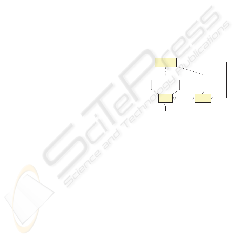
is shown in a simplified UML diagram in Figure 2.
Node
0..n
0..n
child {may be ordered}
{acyclic}
parent {may be ordered}
dependant
0..n
depends on {cyclic}®
ruler
0..n
Attribute
0..n
1
Dependency
0..1
dependant
0..n
0..n
ruler
0..1
Figure 2: The attributed scene graph model.
This model centers around nodes that may have
an arbitrary number of attributes of different types to
store data. Every node has a unique identifier and
a type. Node attributes are identified by names. A
node can be connected to an arbitrary number of child
and/or parent nodes. The latter enables nodes to be
shared in a scene graph’s composition hierarchy, a
feature that not all 3D DCC tools provide. A node’s
children and parents may be ordered. To order child
nodes is e.g. needed for the so-called switch nodes.
There are no cycles allowed in the parent-child hier-
archy, i.e. this part of the attributed scene graph model
corresponds to the classic DAG structure.
The cyclic part of our model provides dependency
relationships to express that one node depends on an-
other one (e.g. because it needs to access the other
node’s data or adapt itself to certain changes of the
other node). Dependencies bear a description and
may reference attributes of nodes. This feature allows
us to easily map scene graph models that have been
designed or influenced by Silicon Graphics − and
therefore use some kind of routes − to our attributed
scene graph model.
We have formally defined our attributed scene
graph model in an XML schema which allows us to
COLLABORATION ON SCENE GRAPH BASED 3D DATA
261

code and exchange such scene graphs as XML files.
We did not use an existing XML based digital asset
exchange solution, like COLLADA (Barnes, 2005),
because these tend to concentrate on aspects that are
less important to our application purpose, like e.g.
finding common ways to represent graphical and ani-
mation primitives. Our main focus is not on the scene
content’s detailed representation but on its structure
and dependencies. We also need a scene’s mapping to
our general scene graph model to be absolutely loss-
less, which exchange formats usually do not provide:
Creating a scene with a 3D DCC tool, exporting it
into an exchange format file and then reimporting the
file into the DCC tool, usually does not yield exactly
the same scene graph, but only a scene that looks the
same. The next section will explain how the attributed
scene graph model fits into the overall architecture of
our system.
4 SYSTEM ARCHITECTURE
The central part in our system is the scene graph
repository server which provides operations for man-
aging and versioning scenes in the attributed scene
graph model. The actual scene data is stored in a
database using an OODBMS, but a graph-oriented
database systems, like GRAS (Kiesel et al., 1995),
would also be a suitable choice. Artists access the
scene graph repository through plug-ins for their DCC
tools. The following example demonstrates how
scene graph data “flows” through the repository sys-
tem’s architecture which is shown in Figure 3.
Let us assume that a Maya artist has created a new
3D scene and wants to store it in the scene graph
repository. He does so by invoking the check-in oper-
ation of the attributed scene graph (ASG) plug-in for
Maya. This plug-in traverses the Maya scene graph
and maps it losslessly to an attributed scene graph
which is encoded in XML and sent to the scene graph
repository. The repository server parses the XML data
into its own attributed scene graph implementation,
registers a new version for the scene and stores it in
the database. If the artist later wants to make changes
to his scene, he uses the Maya plug-in to query the
scene graph repository for the scene and then invokes
the check-out operation. The repository server reads
the scene from its database and encodes its attributed
scene graph data in XML and sends the XML data to
the Maya plug-in. The plug-in parses the XML data
and recreates exactly the same Maya scene graph that
was checked-in by the artist before.
The same processes hold for any other supported
DCC tool, because application specific tasks (e.g.
encoding losslessly the complete application scene
graph into ASG XML data) are encapsulated into the
corresponding ASG plug-ins. With scene description
languages, like VRML, no plug-in is needed, as the
scene graph data can be directly parsed from a scene
file. Checking-out or -in scenes that have not been
worked on in parallel by different artists mainly in-
volves the mapping of application scene graphs to at-
tributed scene graphs and vice versa, but not the key
operation of the collaborative versions concept, i.e.
the merging of scenes. In the next sections we show
how to realize this key operation.
5 MERGING
Merging two versions S
A
and S
B
of a scene S that has
been modified in parallel by artists A and B means
combining the changes of both artists into one new
scene version S
M
. To do so it is essential to know all
changes C
A
and C
B
that artist A and B have applied
to the scene S. The merging of the two scenes S
A
and S
B
can then be reduced to the merging of the so-
called change sets C
A
and C
B
into a single change
set C
M
. The merged scene S
M
results from applying
all changes in C
M
to S. We show now how change
sets can be determined.
5.1 Change Sets
There are two different approaches to track scene
changes, i.e. state-based and operation-based. To de-
termine operation-based changes, a plug-in for every
DCC tool would have to record all the tool’s oper-
ations on a scene as an artist is modifying it. Un-
fortunately, detailed monitoring of operations is not
supported by all DCC tools. In addition, working
with operation-based changes requires the necessary
recording plug-ins to be installed. If an external artist,
who does not have such a plug-in installed, is handed
over a scene from the repository to work on, it is diffi-
cult to later incorporate his modifications to the scene
into the scene graph repository because of the miss-
ing set of changes. Therefore we use a state-based
approach.
To determine changes between two scene versions,
their attributed scene graphs are compared node by
node and changes in state are collected into a change
set. As mentioned before, every node has a unique
ID, and node attributes are identified by names. This
allows us to reliably and efficiently find the corre-
sponding nodes and attributes that have to be com-
pared between two attributed scene graphs. Without
node IDs, corresponding nodes would have to be de-
duced from the scene graph structure alone, which is
a costly and error prone task as related work (Cob
´
ena
et al., 2002) shows that deals with the comparison of
hierarchical XML data. The following list shows the
GRAPP 2006 - COMPUTER GRAPHICS THEORY AND APPLICATIONS
262

Queries
Check-in/-out
Update
Revision Control
Converters
etc.
Operations
Scene Graph Repository
Server
Clients
Conversion
from/to XML
Data Model
Attributed
Scene Graph
Versioning
Change Sets
DBMS
DCC Tools
3ds max
Maya
VRML/X3D
Conversion from/to ASG
ASG-
Plug-in
ASG in XML
write
read
check-out
check-in
Figure 3: Architecture of the scene graph repository system.
types of changes we determine when comparing two
attributed scene graphs:
• AddNode, DeleteNode
• AddAttribute, RemoveAttribute
• SetAttribute
• AddDependency, RemoveDependency
• AddHierarchy, RemoveHierarchy, ReoderChil-
dren, ReorderParents
Each change affects a specific node and possibly
a specific attribute (e.g. an AddNode change only
affects a node whereas a SetAttribute change also
affects an attribute). After having determined the
change sets C
A
and C
B
, merging can be easily done
by building their union C
M
= C
A
∪ C
B
, but only
if there occur no changes in C
A
and C
B
that conflict
with each other. How to detect conflicting changes
will be explained in the next section.
5.2 Conflict Detection
For the detection of conflicts we set up a conflict de-
tection matrix with the change types listed above as
labels for both the rows and the columns. Each matrix
position holds a Boolean expression whose arguments
are expressed using the change types of the corre-
sponding row and column. If such an expression eval-
uates to “true” for two changes, these changes conflict
with each other. Evaluating such a conflict detection
expression for each possible change pair would be
rather inefficient. Fortunately it is sufficient to only
evaluate changes that affect the same node, because
changes that affect different nodes obviously cannot
directly conflict with each other.
Conflict detection may be implemented at the node
level or finer at the attribute level. In the first case,
changes from two different change sets conflict with
each other if they affect the same node and are not
identical. This leads to a simple conflict detection ma-
trix containing simple expressions. For every change
pair it is sufficient to only check the IDs of the nodes
affected by its changes. But such a conservative
scheme may report two changes as conflicting that ac-
tually are compatible. E.g. modifying a node’s posi-
tion attributes and adding an additional child to that
node hardly conflict with each other.
The second form of conflict detection works at the
attribute level and demands more complicated conflict
detection matrices. Of course, if two changes try to
set the same node attribute using different values they
always conflict with each other. Yet in some other
cases, actual conflicts may depend on special proper-
ties of the DCC tool’s scene graph. For a DCC tool
that allows node attributes to have a fan-in of depen-
dencies, two changes adding dependencies which af-
fect the same node attribute do not conflict with each
other, but for a DCC tool that forbids such fan-ins they
do. If such properties are global to a DCC tool’s scene
graph they can be directly encoded in the correspond-
ing conflict detection matrix’ expressions. But if these
properties are local to nodes and their attributes, they
have to be encoded in the node types, and this infor-
mation has then to be taken into account by the corre-
sponding expressions in the conflict detection matrix.
By adding more information to the node type de-
scriptions and more complexity to the conflict de-
tection matrix expressions, conflicts can be detected
more precisely, but to do so the DCC tool’s scene
graph model has to be analyzed first. Therefore when
making a new DCC tool’s scene graph known to the
repository it is reasonable to start with a node based
conflict detection matrix and then refine it for cases
where conflicts have been detected too pessimisti-
cally.
5.3 Conflict Resolution
Merging two change sets C
A
and C
B
by building their
union C
M
= C
A
∪ C
B
is not possible if there are
changes c
A
∈ C
A
and c
B
∈ C
B
that conflict with
each other. Essentially there is only one way to re-
solve such a conflict, i.e. either c
A
or c
B
has to be
dropped. Therefore, resolving conflicts means choos-
ing from conflicting changes those to be kept and
those to be dropped.
When an artist checks-in his local working copy to
COLLABORATION ON SCENE GRAPH BASED 3D DATA
263

the repository and his changes must be merged with
another artist’s changes, his complete working copy
is first registered as a new alternative scene version
before the merging takes place. This makes sure that
the artist’s changes cannot get lost and that changes
that were dropped during the merging can later be
selected and ported to another scene version, if re-
quired. This feature allows us to establish aggressive
automatic merging policies.
If there is a strict hierarchy defined among the
artists, a reasonable automatic merging policy con-
sists in always dropping changes by a junior artist
that conflict with changes by a senior artist. If re-
quired, the senior artist may still port some of the
junior artist’s changes later to the current version of
the scene. If the artists are collaborating peers, the
artist checking-in his local working copy of a scene
to the repository may be given the opportunity to de-
cide himself if his conflicting changes should override
other artists’ changes or should be overridden them-
selves. Of course, artists may also analyze their con-
flicting changes together and choose the changes to
keep or drop on a per conflict basis.
More advanced conflict resolution does not only in-
volve discarding changes which conflict with other
changes, but also changes that relate to conflicting
changes. If conflicts have been found in a certain part
of a scene, an artist sometimes does not only want to
make sure that his changes override other conflicting
changes in that part but also that the part as a whole
remains exactly the same as in his version. Therefore,
while checking-in a scene, an artist may specify a sub-
graph of the scene where only his changes are taken
into account and where changes from other artists to
this subgraph are dropped.
At the end of the conflict resolution process results
the merged change set C
M
containing changes from
C
A
that do not conflict with changes from C
B
and
vice versa. Changes in C
A
and in C
B
but not in C
M
are not lost and can still be applied later to a selected
scene version if required.
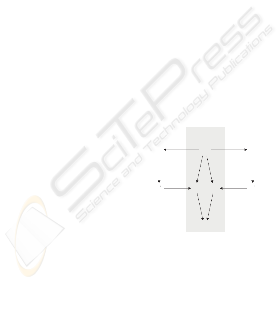
5.4 Indirect Conflicts
Even if artists A and B make only changes to a scene
that do not conflict, their changes might still not be
consistent. We illustrate this by giving a simple exam-
ple for such inconsistent collaborative scene changes
in Figure 4. It shows a scene graph (a) that groups two
rectangles to model the character T in the scene S (b).
Obviously there occurs a problem, i.e. a small gap
arises between the two rectangles. Let us assume that
artists A and B both close this gap within collabora-
tive versions. To do so, artist A extends the vertical
rectangle as shown in (c), and artist B extends the hor-
izontal rectangle as shown in (d). Because both artists
only modify different nodes, merging their collabora-
tive versions S
A
and S
B
into S
M
does not yield any
conflicts, yet S
M
does not look right as it is shown in
(e): The gap between the rectangles in S has disap-
peared, but they now overlap in S
M
.
The problem just shown is an illustration of what
we call indirect changes. The group node in (a) aggre-
gates the two rectangle nodes and therefore depends
on them. Changing one of the group node’s children
indirectly also changes the group node itself. More
generally, a change to a scene graph node indirectly
changes all nodes that depend on it, i.e. by propaga-
tion of indirect changes along hierarchy and depen-
dency relationships.
An indirect change affects a node and possibly also
a node attribute. Indirect changes introduced by hi-
erarchy relationships only affect nodes whereas indi-
rect changes introduced by dependency relationships
may also affect node attributes for attribute dependen-
cies. Indirect changes can be computed recursively:
A change or indirect change that affects a node in-
troduces an additional indirect change for every node
that depends on that node by hierarchy or depen-
dency. Because of possible cycles in dependency re-
lationships, care must be taken when computing in-
direct changes. Every indirect change includes a root
change where it originates from and knows its preced-
ing indirect change if there is one.
Computing all indirect changes for all direct
changes c ∈ C
A
that artist A applied to S yields the
set I
A
of all changes artist A made indirectly. When
merging the two change sets C
A
and C
B
, not only
direct conflicts but also indirect conflicts can now be
detected. If an indirect change i
A
∈ I
A
affects the
same node as an indirect change i
B
∈ I
B
, and i
A
and i
B
originate from different root changes, the two
indirect changes conflict. That is exactly what hap-
pens at the group node in Figure 4 and leads to the
overlapping rectangles in (e). Indirect conflicts iden-
tify nodes where the effects of different changes from
artists A and B meet. For the group node in (e) these
changes are the extensions of the vertical and horizon-
tal rectangles caused by A and B.
If an indirect conflict has been detected in a node
it propagates along dependency and especially hierar-
chy relationships. Such propagated indirect conflicts
are only of limited interest because they are just a
manifestation of an indirect conflict that has already
occurred deeper within the scene graph. Therefore
we only consider indirect conflicts in nodes where the
changes from artists A and B meet for the first time.
For indirect changes i
A
∈ I
A
and i
B
∈ I
B
affect-
ing the same node n, no indirect conflict is registered
if both their preceding indirect changes have already
affected the same node m.
Detecting indirect conflicts allows us to systemati-
cally check the effects that collaborative changes have
on each other and to track down unexpected side ef-
GRAPP 2006 - COMPUTER GRAPHICS THEORY AND APPLICATIONS
264

group node
primitives
scene graph
S
A
SS
B
S
M
(a) (b) (c) (d) (e)
Figure 4: An indirect conflict resulting in overlapping rectangles.
fects of changes that may not have been taken into ac-
count by the artists. Therefore, inspecting nodes with
indirect conflicts helps ensuring a scene’s consistency.
If the indirect conflict in the group node of the scene
S
M
in Figure 4 had been reviewed by an artist, the
overlapping problem would have been identified and
could have been fixed.
To bring possible problems caused by indirect
changes to an an artist’s attention, nodes with indirect
conflicts must be isolated in the scene and, if possi-
ble, be visually presented to the reviewing artist. If an
artist detects a problem, the root changes of the con-
flicting indirect changes can be consulted in order to
figure out what went wrong. Indirect conflicts result
from the effects that changes by two different artists
have on a scene graph. Therefore resolving indirect
conflicts is similar to resolving direct conflicts: If the
indirect changes i
A
∈ I
A
and i
B
∈ I
B
conflict with
each other, either the root change of i
A
or that of i
B
has to be dropped to resolve this indirect conflict. Yet
an artist may also prefer not to deal with changes at
all and to directly fix a problem in the scene where the
indirect conflict has occurred.
Of course, not all indirect conflicts lead to a prob-
lem that needs to be addressed; in fact, most indirect
conflicts will not. Inspecting indirect conflicts is just a
way to systematically and purposefully look for pos-
sible problems at the right places, as opposed to ran-
domly scanning the whole scene.
For every indirect conflict we register the distances
from the originating root change nodes to the node
where the indirect changes meet in a conflict. The
reason is that we assume that local indirect conflicts,
whose causing root changes are not far away, are more
likely to identify problems than rather global indirect
conflicts, whose causing root changes are spread far
away in different parts of the scene graph. This makes
it possible to first review indirect conflicts that are
more likely to be critical.
Computing indirect changes and detecting indirect
conflicts are only possible because of the underlying
general attributed scene graph model which makes the
exact structure of a scene known to the scene graph
repository. In addition to the hierarchy and depen-
dency relationships between nodes, also internal at-
tribute dependencies of nodes have to be taken into
consideration. Such internal dependencies are defined
within the node types.
6 A PRACTICAL EXAMPLE
The authors’ research group is currently developing a
3D model of the old part of the city of Bern. A pro-
totype version of the scene graph repository system
has been applied to this model, and its capability to
enable collaboration could be successfully tested.
To be able to model all the buildings needed in rea-
sonable time a special plug-in for Maya has been de-
veloped (Zaugg, 2005). It allows us to automatically
construct a building typical for the city of Bern from
a building’s ground plan and from some additional
parameters that are directly attached as attributes to
its ground plan polygons in Maya. Historically im-
portant or complex buildings, like towers, churches,
fountains, etc., have to be manually modeled in Maya
from scratch.
There are several people involved in building this
city model. One modeler acquires ground plan poly-
gons and defines the rough parameters for the houses
to be built upon them. Another modeler erects houses
from the ground plan polygons using the special
building plug-in and fine-tunes their parameters to
achieve a consistent overall appearance of the city.
Some of the ground plan polygons correspond to
those important buildings that need to be manually
modeled in detail by additional modelers. Yet an-
other modeler decorates buildings with advertisement
signs, flowers, etc. to add further “realism” to the city
model.
All these modelers can work in parallel on the same
model without locking out each other. Each time
they check-in or update their scene they can see what
their collaborating modelers added or changed and
can adapt their own work accordingly. This helps to
ensure an overall consistent appearance of the model
and to sort out different opinions on aspects of the
model as early as possible.
A modeler of a historical building can create his
COLLABORATION ON SCENE GRAPH BASED 3D DATA
265

model directly within the city model, which allows
him to adjust his model to the surrounding buildings
at the time he creates it. If he needs to change some
of the surrounding buildings to fit in his model cor-
rectly, he can do so immediately in his own scene and
does not have to search for and to open the reference
file which contains the buildings he wants to change.
Therefore he will also not run into the problem that
a specific reference file might already be in use by
someone else and is not available for him to work on.
Detection and resolution of conflicting changes by
the repository system during the check-in of scenes
keeps the city model in a clean state. In addition, the
detection and inspection of indirect conflicts helps to
keep the city model consistent. If two modelers have
accidentally decorated the same building this would
result in an indirect conflict in the affected building.
During a check-in or an update this indirect conflict
would be brought to the modelers’ attention and the
problem could be fixed.
7 CONCLUSIONS
Today’s professional 3D digital content creation tools
only offer limited support for several artists to work
collaboratively on a 3D scene, and also standard
group authoring tools are only of limited assistance,
because they are not able to merge collaborative
changes made to 3D scenes. To make the merging
of 3D scenes possible we have presented an attributed
scene graph model that is general enough to handle
scene graphs of different DCC tools.
We have also presented a scene graph reposi-
tory system that enables fine-grained collaboration on
scenes of standard 3D DCC tools by implementing
the concept of collaborative versions. Artists can now
work on the same scene in parallel without locking
out each other. The artists’ changes to a scene are reg-
ularly merged to make sure that all artists can see each
other’s progress and can collaborate on current data.
We have reduced the merging of scenes to the merg-
ing of state-based change sets and have shown how to
detect and resolve conflicts between such change sets
using different conflict resolution policies.
We have also introduced the concept of indirect
changes and indirect conflicts which help maintain-
ing scene consistency by systematically looking for
inconsistencies at the right places. Computing indi-
rect conflicts is based on our attributed scene graph
model’s capability to depict detailed dependencies be-
tween nodes.
Our approach has been implemented in a proto-
type scene graph repository server in Java and a Maya
ASG plug-in in C++. We have successfully tested our
prototype implementation by applying it to our model
of the old part of the city of Bern. Merging different
versions of a city model Maya scene, which is about
50 MB in size, by applying an automatic conflict res-
olution policy takes less than 15 seconds on a today’s
standard PC.
REFERENCES
Alienbrain (2005). Alienbrain studio 7. http://www.
alienbrain.com.
Barnes, M. (2005). Collada, digital asset schema release
1.3.0, specification. http://www.collada.org.
Cob
´
ena, G., Abiteboul, S., and Marian, A. (2002). Detect-
ing changes in XML documents. In Proceedings of
the 18th International Conference on Data Engineer-
ing (ICDE’02), pages 41–52. IEEE.
Collison, A. and Bieri, H. (2000). A component-based sys-
tem for storing and manipulating graphics objects of
different representations. In The Visual Computer,
volume 16(6), pages 322–338. Springer.
Galli, R. and Luo, Y. (2000). Mu3d: a causal consistency
protocol for a collaborative vrml editor. In VRML ’00:
Proceedings of the fifth symposium on virtual real-
ity modeling language (Web3D-VRML), pages 53–62,
New York, NY, USA. ACM Press.
Hesina, G., Schmalstieg, D., Fuhrmann, A. L., and Purgath-
ofer, W. (1999). Distributed open inventor: a practical
approach to distributed 3d graphics. In VRST, pages
74–81.
Kiesel, N., Sch
¨
urr, A., and Westfechtel, B. (1995). Gras,
a graph-oriented (software) engineering database sys-
tem. Information Systems, 20(1):21–51.
Magnusson, B., Asklund, U., and Min
¨
or, S. (1993). Fine-
grained revision control for collaborative software de-
velopment. In Proceedings of the first ACM sympo-
sium on Foundations of software engineering, pages
33–41. ACM Press.
Naef, M., Lamboray, E., Staadt, O., and Gross, M. (2003).
The blue-c distributed scene graph. In Proceedings of
the IPT/EGVE Workshop 2003, pages 125–133.
Wieczerzycki, W. and Rykowski, J. (1994). Version sup-
port for cad/case databases. In Proceedings East/West
Database Workshop, Workshops in Computing, pages
249–260.
Zaugg, M. (2005). Generische Geb
¨
audemodellierung in
Maya. Master Thesis, Institute of Computer Science
and Applied Mathematics, University of Bern.
Zeleznik, B., Holden, L., Capps, M., Abrams, H., and
Miller, T. (2000). Scene-graph-as-bus: Collaboration
between heterogeneous stand-alone 3-D graphical ap-
plications. In Computer Graphics Forum (Eurograph-
ics 2000), volume 19(3).
GRAPP 2006 - COMPUTER GRAPHICS THEORY AND APPLICATIONS
266
