
MOTION MAP GENERATION FOR MAINTAINING THE
TEMPORAL COHERENCE OF BRUSH STROKES
Youngsup Park
Chung-Ang University
221 HukSeok-Dong, DongJak-Gu, Seoul, Korea
KyungHyun Yoon
Chung-Ang University
221 HukSeok-Dong, DongJak-Gu, Seoul, Korea
Keywords:
Non-photorealistic Animation, Painterly Animation, Motion Map, Temporal Coherence, Strong Edge, Local
Gradient Interpolation.
Abstract:
Painterly animation is a method that expresses images with a handpainted appearance from a video, and the
most crucial element for it is the coherence between frames. A motion map generation is proposed in this
paper as a resolution to the issue of maintaining the coherence in the brush strokes between the frames. A
motion map refers to the range of motion calculated by their magnitudes and directions between the frames
with the edge of the previous frame as a point of reference. The different methods of motion estimation used
in this paper include the optical flow method and the block-based method, and the method that yielded the
biggest PSNR using the motion information (the directions and magnitudes) acquired by various methods
of motion estimation has been chosen as the final motion information to form a motion map. The created
motion map determined the part of the frame that should be re-painted. In order to maintain the temporal
coherence, the motion information was applied to only the strong edges that determine the directions of the
brush strokes. Also, this paper sought to reduce the flickering phenomenon between the frames by using the
multiple exposure method and the difference map created by the difference between images of the source and
the canvas. Maintenance of the coherence in the direction of the brush strokes was also attempted by a local
gradient interpolation in an attempt to maintain the structural coherence.
1 INTRODUCTION
The most crucial element in a painterly animation
with an input of a video is to maintain the coherence
in the brush strokes between frames. This paper pro-
poses a motion map in order to resolve the issue of
maintaining the coherence of brush strokes between
frames in a painterly animation.
One of the basic information needed for the per-
ception of the objects moving between frames (the
foreground and the background) is the information of
edges. The information of edges is a standard that dis-
tinguishes between the objects in a video and an es-
sential element that visualize the motion. The motion
map suggested in this paper is created using the in-
formation of edges as well as the motion information.
In other words, a motion map refers to the range of
a motion calculated by the magnitudes and directions
of the motions of each object between frames with the
edge of a previous frame as a point of reference, and
the area where brush strokes should be newly created
when passing on to the next frame. Our painting al-
gorithm, applying the similar methods applied to the
paint-on-glass animations, has sought to maintain the
coherence of brush strokes between frames by apply-
ing new brush strokes by determining at the area of
the motion map the area of the previous canvas where
it should be re-painted to produce the images of the
next frame.
Motion information can be acquired by the meth-
ods of motion estimation, such as the optical flow
method(Horn and Schunck, 1981)(Lucas and Kanade,
1981) and the block-based method(Koga et al., 1981)
(Tekalp, 1995). The motion information created by
using the optical flow method accurately shows the di-
rection of the motion, but it does not accurately depict
the exact magnitude of the motion as a result of the
noise and/or occlusion problem of the images(Tekalp,
1995). Although Litwinowicz(Litwinowicz, 1997)
and Hertzmann(Hertzmann and Perlin, 2000) have
produced motion information using the optical flow
method, this paper sought to improve the accuracy of
the motion information by choosing among the three
methods of motion estimation(Horn and Schunck,
158
Park Y. and Yoon K. (2006).
MOTION MAP GENERATION FOR MAINTAINING THE TEMPORAL COHERENCE OF BRUSH STROKES.
In Proceedings of the First International Conference on Computer Graphics Theory and Applications, pages 158-167
DOI: 10.5220/0001354101580167
Copyright
c
SciTePress

1981)(Lucas and Kanade, 1981)(Koga et al., 1981)
the method that yields the greatest PSNR. This paper
also sought to maintain the coherence between frames
by applying the motion information to strong edges
that determine the direction of brush strokes among
other elements.
The character of brush strokes is determined by
such elements as the color, the direction, the size,
and the shape. Most of the painterly rendering algo-
rithms(Litwinowicz, 1997)(Hertzmann, 1998)(Hays
and Essa, 2004) use a very simple form of brush
strokes that have the same shapes and sizes among
the characteristics of brush strokes. For such reasons,
the resulting images convey a static, machine-like at-
mosphere, unlike the active and intense effects of the
actual paintings. This paper, however, created brush
strokes of diverse directions, sizes, and lengths using
the linear and curvy shapes and local gradient interpo-
lation, and applied them to the motion map in order to
produce a painterly animation.
2 RELATED WORK
Litwinowicz and Hertzmann used the optical flow
method for motion estimation in order to move the
brush strokes from the previous frame to the cur-
rent one(Litwinowicz, 1997)(Hertzmann and Perlin,
2000). This method, however, calculates the motion
using only the intensity information between neigh-
boring pixels, and thus, the occlusion problem be-
tween a foreground and a background and between a
foreground and another foreground is neglected. This
paper used both the optical flow method(Horn and
Schunck, 1981)(Lucas and Kanade, 1981) and the
block-based method(Koga et al., 1981) in order to re-
solve the problems associated with using twodimen-
sional image, among the various methods of motion
estimation chose the method with the biggest PSNR.
Hertzmann(Hertzmann and Perlin, 2000), in order
to maintain the coherence of the brush strokes be-
tween frames, applied new brush strokes on the re-
painting part of the next frame by using the paintover
method, similar to the paint-on-glass method, differ-
ence masking, and the motion data. His method, how-
ever, has two problems. First, because a video has
noises and/or the occlusion problem, the motion in-
formation calculated between frames is not accurate.
Hertzmann failed to resolve the problem of flicker-
ing by applying his motion data to every element
such as the directions, locations, and shapes of the
brush strokes(Hertzmann and Perlin, 2000). This pa-
per sought to decrease the flickering phenomenon by
applying the motion data only to the strong edges
that determine the directions of the strokes and using
the motion map elsewhere. Second, in a real paint-
on-glass animation, the coherence between frames is
maintained by using the canvas of the previous frame
as the initial canvas for the next frame and by applying
brush strokes only to where it should be re-painted.
Hertzmann(Hertzmann and Perlin, 2000), however,
warped the canvas of the previous frame using the in-
accurate motion data, and used that warped canvas as
the initial canvas for the next frame. Also, he cal-
culated the difference masking not by using the im-
ages of the current source and the initial canvas, but
by comparing the images of the previous sources with
the images of the current sources. When using the dif-
ference masking calculated in such a way to paint the
brush on the previously warped canvas, it may show
much difference from the images of the current source
and continue the flickering phenomenon onto the next
frame. It is because the image with the most main-
tained coherence is an image of a source. This paper
sought to maintain the coherence between frames by
calculating the difference map between the image of
the current source and the canvas onto which the mo-
tion map had been applied.
Hays redefined the characteristics of the brush
strokes and produced brush strokes for each frame be-
cause a hole had appeared on the canvas due to the
imperfect motion information and/or a phenomenon
of partially erased characteristics of the brush strokes
had appeared on the canvas(Hays and Essa, 2004).
Hays method, however, also has disadvantages as it
applies a process of decreasing the opacity by 10%
for each frame in an attempt to avoid the flickering
that emerge in the process of the redefinition of brush
strokes. It is too dependent on opacity, in other words.
The method also conveys a feeling of mere movement
of brush strokes between frames by using only line
brush strokes for the texture.
3 CREATION OF THE MOTION
MAP
Motion estimation refers to the estimation of the vec-
tors of the motion between the previous frame and the
current frame. The method proposed by in this paper
employed for motion estimation include: the method
of finding the pixel with the minimum pixel-to-pixel
variation among the flow vectors(Horn and Schunck,
1981); the method of motion estimation based on an
assumption that the motion vector remains unchanged
over a particular block of pixels(Lucas and Kanade,
1981); and the block-based method that, using the
block mask, finds the pixels with the best-matching
block of the same size(Koga et al., 1981). Based on
the motion information(the directions and the mag-
nitudes) gathered by using these methods, this paper
chooses the method with the biggest PSNR.
MOTION MAP GENERATION FOR MAINTAINING THE TEMPORAL COHERENCE OF BRUSH STROKES
159
A motion map is created by applying the method
of perceiving an object in the channel that handle the
forms and movements among other channels of han-
dling the visual information, and this method of per-
ception is reflected upon the edges of the moving ob-
ject in focus. This paper creates a motion map by find-
ing the range of the motion with the edge of the pre-
vious frame as a point of reference using the motion
vectors found by the motion estimation. The newly
created motion map determines where should be re-
painted in the next frame and maintains the coherence
in brush strokes between the frames.
3.1 Motion Estimation
The HS(Horn and Schunck, 1981) and LK(Lucas and
Kanade, 1981) optical flow method can apply motion
estimation to the whole range of an image and the di-
rection of the motion in its information is accurate,
while the magnitude of the motion is not. On the con-
trary, the BM(Koga et al., 1981) method that looks for
the pixels with the most correspondence to the previ-
ous frame as much as the size of a block mask per
pixel provides the direction and the magnitude of the
motion more accurate than those of the optical flow
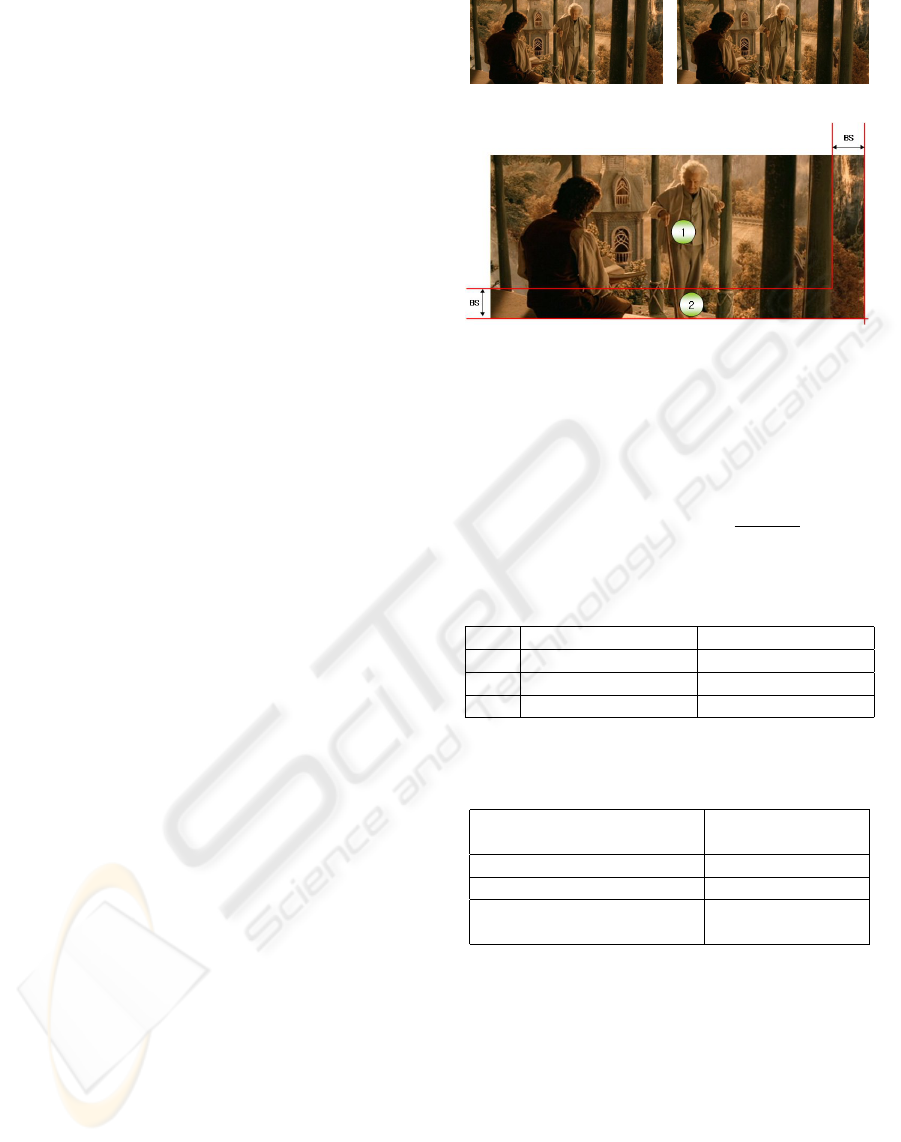
method, despite its disadvantage that the area 2 of
Figure 1(C) cannot calculate the motion information.
This paper chose the method with the biggest PSNR
after calculating each motion vector by dividing the
whole area into area 1 and area 2 just as in Figure 1.
Table 1 is the result of the calculation of the peak sig-
nal to noise applying the optical flow method and the
block-based method to each area. In case of calcu-
lating the motion vectors regarding the image in Fig-
ure 1(A–B), similar to the results shown in Table 1,
after applying the motion information calculated by
the BM method to Area 1 and the motion information
calculated by the LK method to Area 2, the PSNR
is calculated again based on the whole area(Area 1
+ Area 2). Table 2 is the result of the calculation of
the PSNRs from the optical flow method(Horn and
Schunck, 1981)(Lucas and Kanade, 1981) and other
method suggested in this paper. Equation 1–2 is the
formula used to calculate the PSNR, and Element A is
the warped image of the image of the previous source
using the estimated motion information, and Element
B is the image of the current source. This paper does
not always choose the LK and BM methods as in
Tables 1-2, but chooses the method with the biggest
PSNR for each image. This paper also shortened the
rendering time by calculating the motion information
for all the images as a preprocessing step.
T =
SZ
i=1
(A
i
− B
i
)
2
(1)
(a) Previous Image (b) Current Image
(c) Dividing the whole area into area 1 and area 2 for Mo-
tion Estimation (BS : Block Size)
Figure 1: Images applied Motion Estimation and Area Seg-
mentation for Motion Estimation Method.
PSNR(dB)=10∗ log(
65025.0
T/SZ
) (2)
Table 1: 3 PSNR Values for each Area of Figure 1(C).
PSNR(dB)(Area 1) PSNR(dB)(Area 2)
HS 18.86403 19.70797
LK 20.90547 19.75762
BM 26.14414
Table 2: 3 PSNR Values for the whole area of Figure 1(C).
PSNR(dB)
(Area 1 + Area 2)
HS 18.91518
LK 20.81920
OURS
(Area 1:BM + Area 2:LK) 24.83612
3.2 Motion Map
The edge information is one of the important elements
for the visual perception of movements. This paper
created a motion map based on the motion vectors and
the edge information.
Figure 2 shows how a motion map is developed
when a circle moves downward to the right. When
a circle composed of Areas A and B of the previ-
ous frame moves to a circle composed of Areas B
and C in the current frame, Area A transforms from
a foreground into a background, Area B maintains its
GRAPP 2006 - COMPUTER GRAPHICS THEORY AND APPLICATIONS
160
(a) Previous Image (b) Current Image
(c) Creation of Motion Map
Figure 2: Motion map is developed when a circle moves
downward to the right (The point P and Q are a meeting
point between frames, F(x,y,t)=(5 pixels, 5 pixels)).
foreground status despite the movements, and Area C
transforms from a background to a foreground. This
paper creates a motion map that includes Areas A and
C by assuming the area of re-painting for the next
frame as Areas A and C just as it is in the method
of making the paint-on-glass animation. This method
makes a motion map that includes the Areas A and C
by drawing a line from Point P on the edge to Point
Q when the Point P of the previous frame has moved
to Point Q in the current frame. The motion map pro-
posed in this paper has an advantage of easy creating
using the edge and motion information without sep-
arating the foreground and the background. Figure 3
is a motion map using the method suggested by this
paper.
Because the motion map is an area where the
visual changes between frames are apparent, brush
strokes of various sizes were applied in layers to
the initial canvas of the current frame. The method
to decide what size to use for the brush strokes
when applying to a motion map in layers is similar
to Hertzmanns method(Hertzmann, 1998) that forms
one brush stroke in one grid. However, the brush
strokes that go beyond the motion map can be re-
moved by applying the brush strokes only when the
proportion of the grid area and the area of the mo-
tion map exceeds a certain threshold. Figure 3(d)
and Figure 3(e) show the brush strokes created using
the motion map of Figure 3(C). As shown in Figure
3(D), applying brush strokes of various kinds to the
next frame without regarding the size of the motion
map area can cause much difference from the previ-
ous frame, bringing up much more flickering.
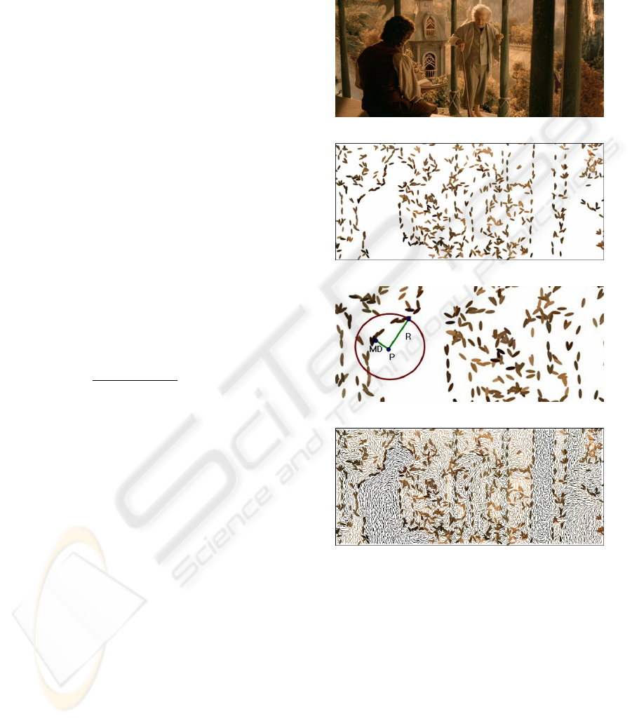
(a) Previous Image (b) Current Image
(c) Motion Map
(d) applying brush strokes of various kinds to the next
frame without regarding the size of the motion map area
(e) applying the brush strokes only when the proportion
of the grid area and the area of the motion map exceeds a
certain threshold(threshold : 50%)
Figure 3: Motion map and the canvas created using the mo-
tion map.
4 MOTION MAP BASED
PAINTERLY ANIMATION
4.1 Direction
Painters usually draw a picture of an object fol-
lowing the edgy line of that object. Litwinow-
icz(Litwinowicz, 1997) proposed a local gradient in-
terpolation. This method determines the directions of
the brush strokes by interpolating the gradients of the
surrounding pixels in case of a pixel with a gradient
located in a certain area with a magnitude near 0. Be-
cause this method applies the interpolation to the area
where the direction of the strokes is not certain, the
MOTION MAP GENERATION FOR MAINTAINING THE TEMPORAL COHERENCE OF BRUSH STROKES
161
direction of the brush strokes does not comply with
the direction of the edges. In order to resolve this
problem, this paper set strong edges that determine
the direction, and made the direction of the surround-
ing pixels correspond to the direction set by the edges.
This is similar to the Hays method(Hays and Essa,
2004), but while Hays(Hays and Essa, 2004) used the
gradient interpolation of the whole area, this paper
used the local gradient interpolation.
There are three steps to finding strong edges: first,
calculating the magnitudes of the gradients of pixels
on the edges using thinned images; second, organize
the calculated sizes of the gradients in a descending
order; third, choose the biggest gradient as a strong
edge and remove the surrounding edges only when
their difference from the strong edge in direction is
smaller than a fixed threshold. Many strong edges can
be found by repeating this process.
The local gradient interpolation method using the
strong edges calculated the weight of the distances
between the edges that are within R radius, which is
N times the shortest distance with the location of P
as a point of reference(Park and Yoon, 2004). The
gradients in pixels were calculated by adding the gra-
dients and weights of the strong edges on the radius R
and dividing the number. Variable N is an experimen-
tal number, and the values between 1.5 and 2.5 were
given to it.
Weight(i)=
MinDistance
Distance(i)
b
,i=1,...,M
(3)
Equation 3 is a gradient interpolation function in
order to calculate the weighted gradient value at each
pixel (x, y). The MinDistance of a element is the
shortest distance from Point P to the strong edges on
the radius R and is expressed as MD. The distance
is the length between Point P and the strong edges
on the radius R. M is the number of the strong edges
on the radius R and b is a constant. Figure 4(c) ex-
plains Point P, MD and Radius R. This method is a
variation of the method of interpolation used in mor-
phing (Beier and Neely, 1992). Figure 4 shows the
strong edges created and the interpolated gradient im-
ages using the method suggested in this paper.
4.2 Color
Colors largely depend on the subjective motivations
of the painters, and each painter has his own palette
of distinctive colors. The Impressionists in particular
were influenced by the flat form of the Japanese color
prints. Considering this, this paper has attempted the
method of flatizing the range of luminosity from 256
levels to 12 levels and the method of quantizing the
colors (Deng et al., 1999b) (Deng et al., 1999a) (Park
and Yoon, 2004). The painterly rendering in partic-
ular is handled by the units of random areas where
the brush strokes are made, not by the pixel units, and
thus, it is unnecessary to apply every color that forms
an image of a source.
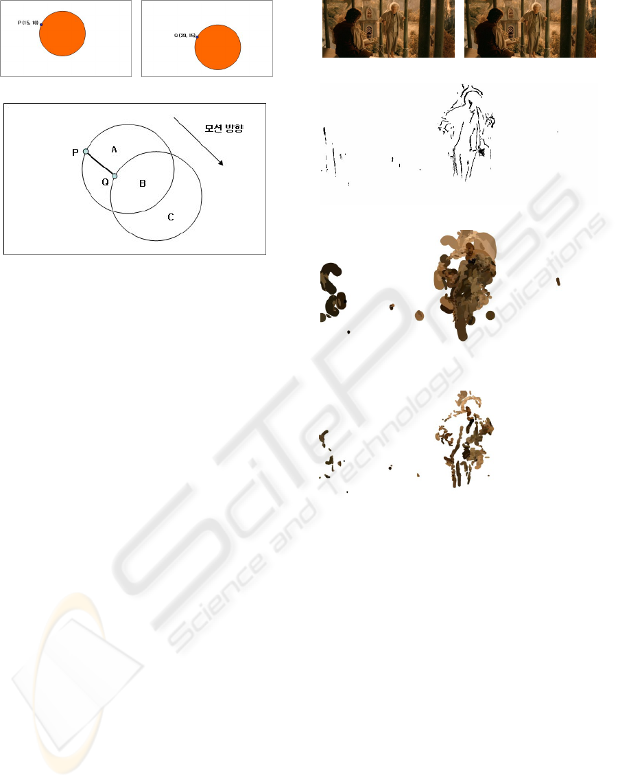
(a) Source Image
(b) Strong Edges Image
(c) Gradient Intepolation Using Strong Edges
(d) Gradient Interpolated Image
Figure 4: Strong Edge Image and Gradient Interpolated Im-
age.
4.3 Shape and Size
Brush strokes have sizes of 4 to 32 pixels depending
on the area of their application. The divided areas
are painted using big brushes first, and then smaller
brushes. The brush strokes are expressed in spline
curves as well as the linear lines as a result of the ap-
plication of the edge clipping. The control points of
the spline curves are chosen in reference to the gradi-
ent interpolation of each pixel, and expanded upward
and downward or left and right with the spline curve
GRAPP 2006 - COMPUTER GRAPHICS THEORY AND APPLICATIONS
162

as a line of reference that follows the minimum of 2
and the maximum of 10 control points along the gra-
dient from the starting point.
4.4 Maintenance of the Coherence
Between Frames
Accurate motion information is necessary for the
maintenance of coherence between frames. The exist-
ing methods of calculating motion information(Horn
and Schunck, 1981)(Lucas and Kanade, 1981)(Koga
et al., 1981) do not provide accurate motion infor-
mation due to the noise or occlusion problem in the
video(Tekalp, 1995). Those who studied the painterly
animation earlier(Litwinowicz, 1997)(Hertzmann and
Perlin, 2000)(Hays and Essa, 2004) cause the flicker-
ing phenomenon by applying the inaccurate motion
information to every element of the brush strokes.
The Hays method especially has a high dependency
on opacity, conveying a feeling of mere movements of
the brush strokes rather than a feeling of re-painting.
This paper has applied motion information only to
the strong edges that determined the element of di-
rection of the brush strokes in an attempt to maintain
coherence between frames. It is because the edge im-
ages found using random thresholds produce differ-
ent results per frame, which may dislocate the strong
edges. When the strong edges change their locations
per frame, so does the direction of brush strokes. Fig-
ure 5 is an image resulting from moving the strong
edges by applying the motion information in an at-
tempt to maintain coherence of the directions of brush
strokes.
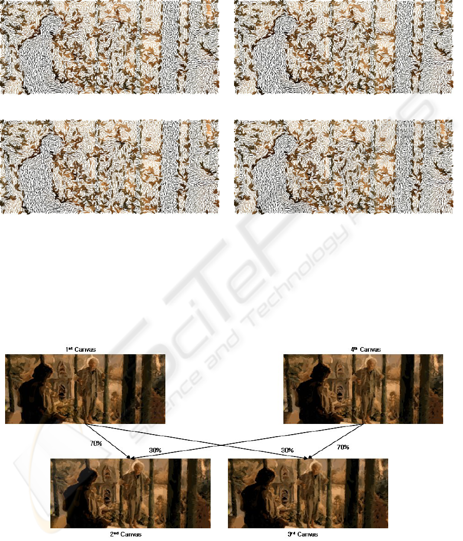
Another method to maintain coherence be-
tween frames is to express the natural move-
ments of the object by applying the multi-exposure
method(Laybourne, 1998) as shown in Figure 6. This
method expressed natural movements of the object by
creating an in-between frame, blending Canvas 2 in
a proportion of 7 (Canvas 1): 3(Canvas 4), and Can-
vas 3 in a proportion of 3 (Canvas 1):7(Canvas 2) af-
ter rendering only Canvases 1 and 4. This method is
effective for the usage in a video with many move-
ments, and has an advantage to alleviate the flickering
phenomenon that can be caused by many differences
in the colors of the brush strokes that are applied to
the same location between frames.
The last method to maintain coherence between
frames is to make a difference map between the can-
vas onto which a motion map has been applied and
the image of the source and the re-paint it using a
small brush. The area of effect of this method is Area
B of Figure 2(c). This Area B had not appeared in
the motion map, despite its motion, because its dif-
ference in intensity was not apparent from the sur-
rounding pixels. Changes of each frame were prob-
able in this area, so a difference map was made using
the difference between the canvas of the applied brush
strokes in the motion map and the image of the source,
and Area B was re-painted with that map as a ref-
erence. Unlike Hertzmanns method(Hertzmann and
Perlin, 2000) that makes a difference map between the
warped image of the previous source and the image
of the current source, the method applied in this pa-
per made a difference map between the canvas where
the area of the motion map had been re-painted and
the image of the current source in an attempt to lessen
the flickering phenomenon between frames. It is due
to the fact that the image with the most coherence be-
tween frames is an image of a source, and the differ-
ence between a warped image of the previous source
and the image of the current source is different from
the difference between the previously warped canvas
and the present canvas. Figure 7(G) is an image re-
sulting from the area without the motion map, and the
smallest brush was used to produce it.
5 RESULTS
Figure 5 is an image resulting from determining the
directions of the brush strokes by applying motion in-
formation only to the strong edges between frames.
This was an attempt to maintain coherence between
frames by applying the motion information, which
could be inaccurate due to the noise and the occlu-
sion problem of the image, not to every element of the
brush strokes (the direction, the location, the color,
the form), but by applying it to only the direction be-
tween frames. Figure 6 is an image resulting from
applying the multi-exposure method. Movements are
naturally expressed by extracting the images of the
source that have 8 frames per second from the video,
rendering them, and blending the images between
them. Figure 7 shows an image resulting from each
step taken to maintain coherence between frames. Co-
herence is maintained by making a difference map
between the image whose brush strokes are created
and repainted by the motion map and the image of the
source. Figure 8 is the images resulting from many
scenes. You can find more images and videos created
by the methods outlined in this paper on the website
at : http://cglab.cse.cau.ac.kr/npr/index.html.
6 CONCLUSION AND FUTURE
WORK
This paper has suggested the method of using a mo-
tion map in creating a painterly animation. The ar-
eas of repainting between frames are distinguished by
MOTION MAP GENERATION FOR MAINTAINING THE TEMPORAL COHERENCE OF BRUSH STROKES
163

the motion map made by the edge and motion infor-
mation acquired from motion estimation. In an at-
tempt to maintain coherence between frames, motion
information was applied to only the strong edges that
determined the directions of the brush strokes, and
the multi-exposure method was used in order to ex-
press the natural movements of the object(Laybourne,
1998). Also, by making a difference map between the
previous canvas and the current image of the source
and applying the smallest brush strokes, the flickering
phenomenon was also lessened.
Among the characteristics of brush strokes, the ef-
fects of color contrast, the brush texture expressed us-
ing rough brushes or knives, and the glazing effects
need to be analyzed and simulated.
REFERENCES
Beier, T. and Neely, S. (1992). Feature based image meta-
morphosis. In SIGGRAPH’92, pages 35–42.
Deng, Y., Kenney, C., Moore, M., and Manjunath, B.
(1999a). Peer group filtering and perceptual color im-
age quantization. In ISCAS’99, pages 21–24.
Deng, Y., Manjunath, B., and Shin, H. (1999b). Color image
segmentation. In CVPR’99, pages 2446–2451.
Hays, J. and Essa, I. (2004). Image and video based
painterly animation. In NPAR’2004, pages 113–120.
Hertzmann, A. (1998). Painterly rendering with curved
brush strokes of multiple sizes. In SIGGRAPH’98,
pages 453–460.
Hertzmann, A. and Perlin, K. (2000). Painterly rendering
for video and interaction. In NPAR’2000, pages 7–12.
Horn, B. and Schunck, B. (1981). Determining optical flow.
In Artifitial Intelligence, pages 185–203.
Koga, T., Iinuma, K., Hirano, A., Iijima, Y., and Ishiguro,
T. (1981). Motion-compensated interframe coding for
video. In NTC’81, pages 531–534.
Laybourne, K. (1998). Animation Book. Three Reviers
Press, 2nd edition.
Litwinowicz, P. (1997). Processing images and video for an
impressionist. In SIGGRAPH’97, pages 407–414.
Lucas, B. and Kanade, T. (1981). An iterative image reg-
istration technique with an application to stereo vi-
sion. In DARPA Image Understanding Workshop,
pages 121–130.
Park, Y. and Yoon, K. (2004). Adaptive brush stroke gen-
eration for painterly rendering. In EG’04 - Short Pre-
sentations, pages 65–68.
Tekalp, A. M. (1995). Digital Video Processing. Prentice–
Hall, 2nd edition.
GRAPP 2006 - COMPUTER GRAPHICS THEORY AND APPLICATIONS
164
(a) 1st Strong Edges Image (b) 4th Strong Edges Image
(c) 7th Strong Edges Image (d) 10th Strong Edges Image
Figure 5: An image resulting from determining the directions of the brush strokes by applying motion information only to the
strong edges between frames.
Figure 6: An image resulting from applying the multi-exposure method.
MOTION MAP GENERATION FOR MAINTAINING THE TEMPORAL COHERENCE OF BRUSH STROKES
165
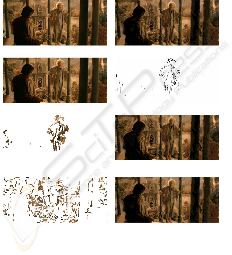
(a) 1st Source Image (b) 1st Final Canvas and 4th Initial Canvas
(c) 4th Source Image (d) Motion Map
(e) applying brush strokes of various kinds to the next
frame with regarding the size of the motion map area
(f) (b)Image + (e)Image
(g) an Image applyied the smallest brush strokes by dif-
ference map between (f)canvas and (c)Image
(h) 4th Final Canvas ((f) Image + (g) Image)
Figure 7: An image resulting from each step taken to maintain coherence between frames.
GRAPP 2006 - COMPUTER GRAPHICS THEORY AND APPLICATIONS
166
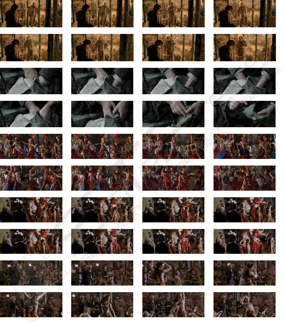
Figure 8: The images resulting from many scenes.
MOTION MAP GENERATION FOR MAINTAINING THE TEMPORAL COHERENCE OF BRUSH STROKES
167
