
ADAPTIVE CONSTRAINT AND 3D SKETCH-BASED
DEFORMATION FOR INTERACTIVE FREE FORM SURFACE
STYLING
Li Han
1,2,3
, Raffaele De Amicis
1
, Giuseppe Conti
1
1
Graphitech, Via Dei Molini, 2, 38100, Trento (TN), Italy
2
Information and Communication Technology Faculty, Trento University, Italy
3
College of Computer and Information Technology Of Liaoning Normal University, Dalian, China
Keywords: Physical-based modelling, adaptive constraint, free form sketching, local deformation.
Abstract: This paper tries to answer to the increasing demand in the domain of conceptual design for more intuitive
methods for creating and modifying free-form curves and surfaces. This is done by addressing the issue of
physical-based shape control by free hand spline sketching instead of the tedious mathematical parameters
adjustment. We present a novel approach capable of matching the designer’s requirements in terms of qual-
ity and accuracy of the produced model. The algorithm adopts a simple 3D sketching technique and a finite
element deformation method to create free-form models. In the method proposed the user applies interactive
sculpting to modify a surface in a predicable way. Our algorithm automatically extracts the key points from
sketched target curve and adaptively distributes the external-force constraints which impose the force energy
on the corresponding control vertexes along their normal. We have limited the influence of these constraints
to a localized area by attaching an influence factor to each control vertex of the parent surface. The smooth-
ing function introduced later further solves the transition interval and it provides for symmetry features. This
proposed method is finally implemented in a 3D scene environment and the results show how the designers
intuitively and exactly control the shape of the surface.
1 INTRODUCTION
Efficient and intuitive shape manipulation techniques
are vital to the success of geometric modeling, com-
puter animation, physical simulation and other com-
puting areas. Recently considerable achievements
have been reached through the adoption of Free-
Form Deformation (FFD) and Extended Free-form
Deformation (EFFD). These embed the whole object
into a tensor product volume, and the volume can be
deformed by means of spline control points while the
embedded object is deformed accordingly. Unfortu-
nately, manipulation of splines is not intuitive. Al-
though other physical-based manipulation ap-
proaches improve the natural operation and a new
medial Axial Deformation method (AxDf) is being
currently proposed to achieve better deformation
results, the degree of freedom available to control
the shape is still limited.
The technique presented here supports fully in-
teractive and intuitive shape control, ranging from
free-form surface creation to predictable shape de-
formation. We proposed three surface generation
modes based on easy freehand sketching. During the
implementation of the deformation, our method
adaptively extracts force constraints and it automati-
cally adjusts the corresponding control vertices in
response to the external force distribution. Further-
more, a series of linear influence functions are intro-
duced to improve the continuity and the symmetry.
The rest of the paper is organized as follows: in
section 2 we present the previous works. Section
describes the parent surface creation and relevant
concepts. In section 4 we detail the implementation
of the algorithm showing how to control the defor-
mation process. Section 5 describes some experi-
mental results. Finally in section 6 we conclude with
a summary and describe the directions of future work.
2 PREVIOUS WORKS
The first modeling deformation technique introduced
into the CAD/CAM field was the method relying on
392
Han L., De Amicis R. and Conti G. (2006).
ADAPTIVE CONSTRAINT AND 3D SKETCH-BASED DEFORMATION FOR INTERACTIVE FREE FORM SURFACE STYLING.
In Proceedings of the First International Conference on Computer Graphics Theory and Applications, pages 392-399
DOI: 10.5220/0001352803920399
Copyright
c
SciTePress

global and local deformations (Barr, 1984). This
method and its improvements (
Güdükbay, 1990) can
provide support for regular deformations such as
twisting, tapping, bending, rotating and scaling.
However the method does not easily yield arbitrary
shapes and, further, it involves tedious and unintui-
tive geometric operations. Free-Form Deformation
(FFD) (
Sederberg, 1986) tackles the issue of generat-
ing more complex objects through geometric model-
ing. Specifically a geometrical element such as a
point, a line, a plane etc. is chosen together with
special weight factors and by taking their weighted
average to express a complex shape. Then, to induce
deformations within such complex shape, those con-
trol points are moved, while the local object points’
coordinates are deemed to remain unchanged: i.e. the
topological structure of the deformed object remains
unchanged (
Bechmann, 1994). In fact, FFD is one of
the most versatile and powerful deformation tools,
however it is not easy for the user to exactly predict
the deformation to exactly reach a desired effect.
Further exact placement of object points is hard to
achieve. In literature (
Kalra, 1992; Lamousin, 1994;
Griessmair, 1989; Coquillart, 1991; Chadwick, 1989) it
is possible to find FFD improved in terms of shape
control functions, whose results have been exploited
in several domains including human body animations
and dynamic flexible deformations. However, while
these approaches increase control flexibility, on the
other hand they require the solution of complex
nonlinear equations with numerical methods.
Another approach which promotes an easier and
more intuitive interface is the so-called Extended
Free-Form Deformation (EFFD) technique proposed
in (
Coquillart, 1990). With EFFD, instead of starting
with the FFD’s set of parallelepipeds control points,
the user configures the initial lattice of control points
taking into account the approximate shape of the
intended deformed shape. However, the user must
know the general shape before starting to model, and
the interface is still a direct representation of the
underlying mathematics.
Thanks to the introduction of constraint points
and radius the authors in (
Borrel, 1994) present a
good technique for local deformation which was
further improved by (
Xiaogang, 2000) to the extent
which, not only it conducts to deformation of point
constraints, but also lines and surfaces constraints.
Léon et al. (
Léon, 1997; Léon, 1995; Léon, 1991) have
linked the control polyhedron of a surface to the
mechanical equilibrium of a bar network by using
the force density concept. Although its effect on the
deformation is very satisfactory in terms of aesthetic
feeling, it often needs the solution of high-order
systems of linear equations which generally need
demanding complex computations.
3 SURFACE CREATION AND
RELEVANT CONCEPTS
In the approach implemented we adopt a physical-
based method that incorporates both external force
energies and internal deformation distributions into
the parent NURBS geometric surface.
During the implementation both the “parent sur-
face” creation by user interactive sculpting and the
“target surface” construction through spline-driven
approach underline the physical meaning and pre-
dictable motion features.
3.1 The Creation of Parent Surface
The so-called “parent surface” is the surface which
will be affected by the deformation. As mentioned
earlier, it can be obtained in three different ways:
1. Geom-filling mode: the designer is allowed
to sketch two or more 3D curves which
serve as the constrained boundary of the
surface.
2. Skinning mode: the designer sketches a sur-
face by using the well-known concept of ex-
trusion. He/she first draws a free-form 3D
curve, then the curve is attached to the
pointer and when the pointer is moving, the
process of surface generation starts and the
shape is immediately shown.
3. Revolving mode: the designer can generate
a surface by revolving a curve around one
axis.
In this process, the technique developed supports
fully freehand curve sketching, and as a result, the
NURBS parent surface is constructed by a “multi-
patch” which is composed of a compatible network
of iso-parametric curves as it is shown in formula 1,
where numRow and numCol represent the number of
iso-parametric curve C(u,v) in U and V directions.
S (
)v,u
numRow
i
(
i
C
∑
=1
; )v,u
numCol
j
(
j
C
∑
=1
); (1)
In the following section, we will further describe
how the constraint-based resultant surface is finally
reconstructed by combining multi-patch with so-
called “physical force” distribution technique.
ADAPTIVE CONSTRAINT AND 3D SKETCH-BASED DEFORMATION FOR INTERACTIVE FREE FORM
SURFACE STYLING
393
3.2 Relevant Concepts
Before illustrating further details of the approach we
first introduce the mathematical representation be-
hind the process presented in the following sections.
Bound curve and Target curve
Let C: φ (u, v) = 0 be a sketched closed-curve in 3D
space. It will be used for deciding the region to be
deformed. The influence factor
E (Q
j
) (0 ≤ j≤ Nt) is
attached to each control vertex
Q
j
within the parent
surface
S (u, v), where Nt is the number of the control
vertex in parent surface. If the control vertex Q
j
lies
inside the bound curve, E is equal to 1 and it can be
influenced by force constraints, otherwise E is set to
0 and it will thus keep a “static” status;
⎩
⎨
⎧
=
0
1
)Q(E
j
0
0
>
≤
)v,u(
)v,u(
jj
jj
ϕ
ϕ
(2)
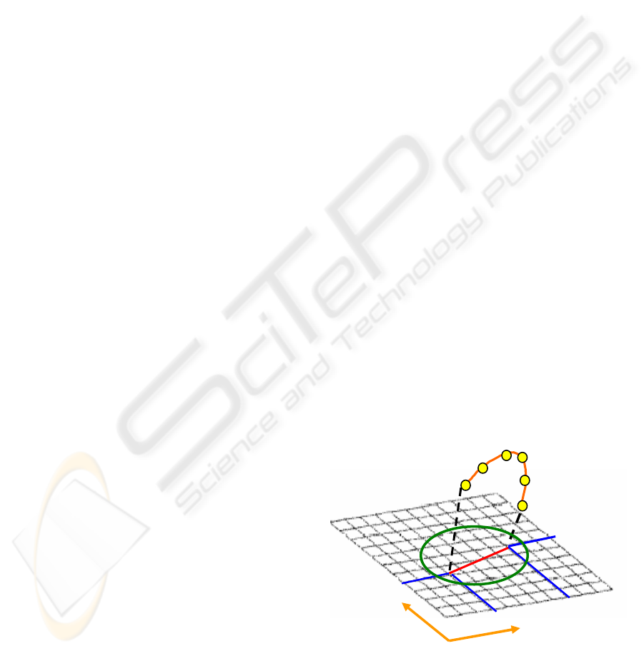
Figure 1: Target curve (in purple) influences only the area
which is inside of the bound curve (in dark)
Likewise the sketched target curve is used to de-
fine the resultant shape by Ψ (u, v) = 0. A series of
force energies are adaptively produced through the
key points on this curve (see Figure 1).
The next section will illustrate how we effectively
obtain these force energies and how they influence
the whole parent surface.
Linear force energy fi (Ki ,P).
We define K
i
as the key points on target curve and D
(K
i
) as the projection distance from K
i
to the parent
surface S (u, v) along the normal N
i
(see Figure 2 -
left). Q
j
is the closest control vertex to the projected
point P which is used for determining the corre-
sponding curve on the parent surface. In this way,
the energy of each force f
i
(K
i
,P) will be distributed
among the vertices on the corresponding curve.
Therefore, the parent surface will be gradually ap-
proximated to the leading target curve (see Figure2 -
right).
⎩
⎨
⎧
==
0
)(
)()(),(
i
ijii
KD
KDQEPKf
(3)
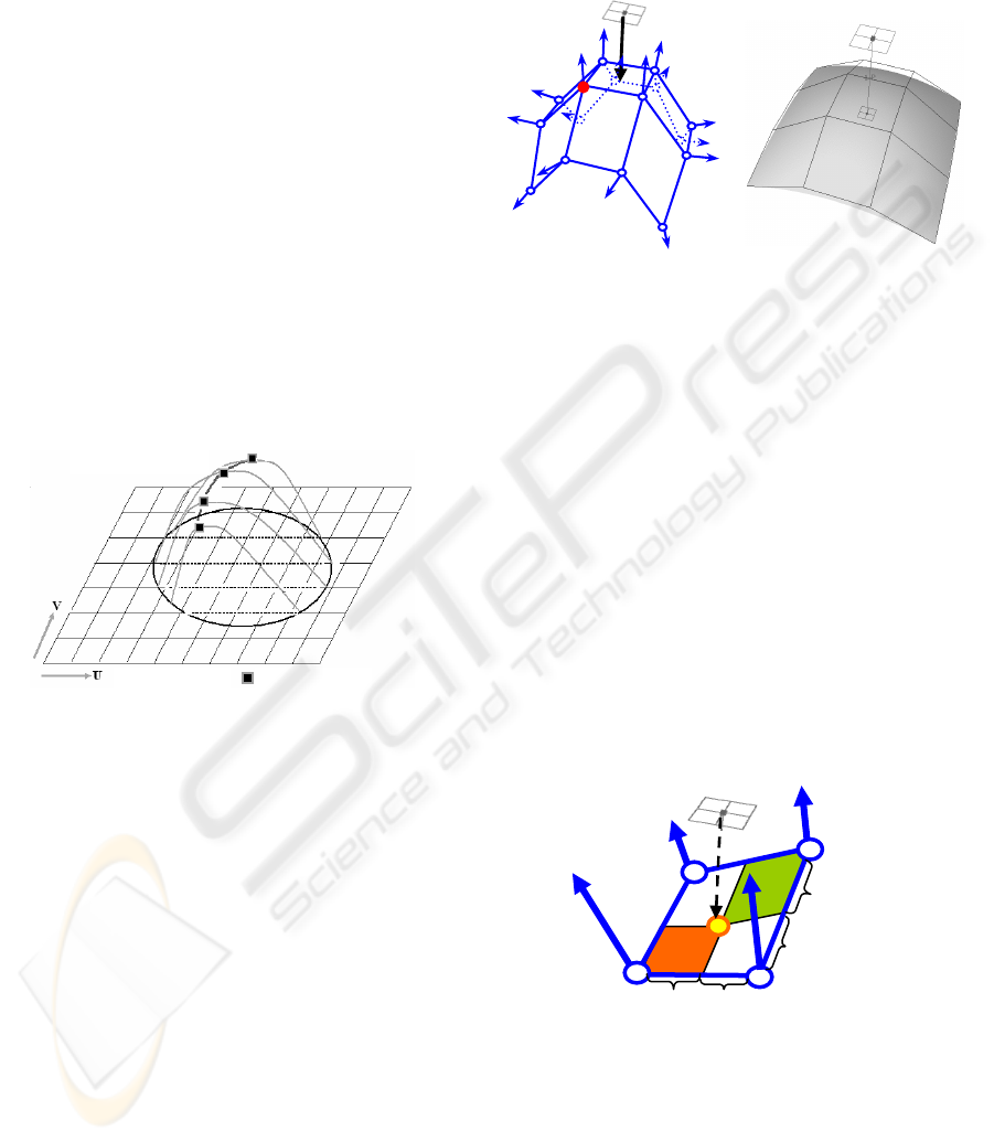
Figure 2: (Left) the multi-patch structure of a surface. K
i
is
the key point which imposes the force energy f
i
to the
patch, and Q
j
is the closest vertex to the projected point P.
(Right) the resultant surface under the influence of the
force f
i
.
The force intensity “α”
Within our model, “α
i
” represents the contribution of
the i
th
force energy to the parent surface S (u, v). If
the projected point P lies in one patch, the force will
be distributed among the neighboring four vertices
(see Figure 3);
α
j
(u
j
, v
j
)
=
α
0
x
b
y
b
(4)
)
i
K(D)
j
Q(E)
j
v,
j
u(
j
)P,
i
K(
i
f)
j
v,
j
u(
j
)
j
Q(F
αα
== (5)
))v,u(Q(F))v,u(C(F
t
Np
t
ti
∑
=
=
1
δ
(6)
Figure 3: Force Intensity distribution in one patch. P is
the projected points from key point K
i
; then as the inten-
sity of the force to the closest vertex Q
j,
“α
j
” is varied
according to the extent of area x
b
y
b
Here x
a
, x
b
, y
a
and y
b
are defined as the distance
from P to the four neighbor vertices, and the unit of
the intensity “α
0
”
is set to “1”. Then the force exer-
cises its effect inversely to the extent of the area.
x
a
y
a
y
b
x
b
P
Q
j
K
i
N
i
K
i
P
Q
j
Parent Surface Key Point
Bound Curve
Target Curve
GRAPP 2006 - COMPUTER GRAPHICS THEORY AND APPLICATIONS
394
Therefore the force’s influence on the control vertex
j
Q can be described as )Q(F
j
(see formula 4, 5). In
formula 6,
))v,u(C(F
i
δ
represents the force’s influ-
ence on the whole curve, where the Np is the number
of control vertex on this curve.
Resultant Surface
Finally we call D
L
the replacement function, which
represents the extent to which the parent surface is
influenced by the force f. We assume Nc as the
number of curves and Nt as the number of the con-
trol vertices on the parent surface, m is the number
of the force constraints. Then the resultant surface S’
(u, v) is obtained as:
∑∑∑∑
==
••=
==
=
m
i
Nt
j
)
i
K(D)
j
Q(E)
j
v,
j
u(
j
m
i
Nc
k
))v,u(
k
C(
i
F)v,u(
L
D
1111
αδ
(7)
)v,u(S)v,u(D)v,u(S
L
+=
′
4 SKETCH-BASED LOCAL
DEFORMATION
4.1 Local deformation algorithm
The algorithm followed briefly depicts the imple-
mentation of local deformation where applicable
through the help of pseudo code description.
Step1: The user creates a free form surface S (u, v)
in the preferred mode (e.g. by geom-
filling, skinning or revolving);
Step2: The user draws a bound curve φ (u, v) and
consequently the system calculates the in-
fluence factor
E (Q
j
) for each vertex.
Step3: The user sketches the target curve
Ψ
(u, v);
IF (Over-constrained) then Goto Step 5;
IF (Under-constrained) or (Well-constrained)
1. The system predicts the motion tendency of
the target curve “_DiR” and it determines the
number of force constrains “m”
2. Switch (_DiR)
Case (U direction):
The curves in V direction evolve by
repositioning control vertexes accord-
ing to each force constraint;
Case (V direction):
Likewise, the curves in U direction
evolve by repositioning control ver-
texes.
3. The system resolves the transition intervals
and it improves the symmetry.
Step4: The system renders the resultant surface
Step5: End
In the following sections we will detail how to ef-
fectively obtain the key points on the sketched target
curve and how to classify three different constraints
configurations to further improve boundary features
of resultant surface.
4.2 The number of force constraints
“m”
Since the designer’s sketching activity produces only
an approximation of the desired shape, it is impor-
tant that the resultant surface captures the “shape”
features of the leading target curve. However, in the
free-form domain, the number of the constraints is
usually unknown. Most current approaches provide
only a solution that is a result of a predetermined
criterion.
We instead propose a method which adaptively
provides such criteria through the prediction of the
motion of target curve (see Figure 4).
We then adopt the partial derivatives θ
1
and θ
2
(see equation 8). As shown in Figure 4 we can easily
get the points P
s
(u
s
,v
s
) and P
e
(u
e
,v
e
) by projecting
K
s
and K
e
onto the parent surface S (u ,v). Then the
span of patches can be obtained, where Cs and Ce
are respectively the curve position in the V direction
while Rs and Re are the curve position in the U di-
rection.
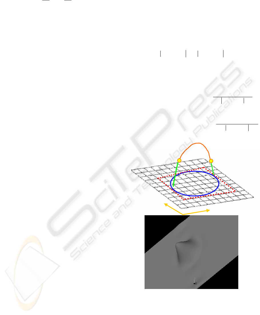
Figure 4: The Parent surface with bound curve (in green)
and target curve (in orange); the yellow circles represent
the key points which are adaptively produced by consider-
ing the value of “m”.
K
s
Pe
Ps
Rs
Re
Ce
Cs
K
e
V
V
U
ADAPTIVE CONSTRAINT AND 3D SKETCH-BASED DEFORMATION FOR INTERACTIVE FREE FORM
SURFACE STYLING
395
When θ
1
≥ θ
2,
the target curve is leading towards
the V direction. Therefore the number of key points
(constraints number) on the target curve “m” is de-
termined by the difference between Ce and Cs. Vice
versa, when θ
1
< θ
2
, “m” is valued by the difference
between Re and Rs. In this way the key points on the
target curve will be adaptively produced and they
will impose the force’s spring to the surface.
4.3 Improvement of the boundary
feature of the resultant surface
During the deformation process, we have excluded
the option of fixing all the control vertices outside
the bound curve and operating only on those inside.
However this choice could still result in an inaccu-
rate and insufficient deformed shape around the
bound curve. Furthermore, the leading target curve
may result over-constrained or just show unaccept-
able undulations.
To avoid these issues, we propose two means to
improve the quality of the result of the deformation.
First, we classify the constraints into three cases:
• Over-constrained: if the target curve com-
pletely lies outside the bound curve.
• Under-constrained: if the target curve partly
lies inside the bound curve.
• Well-constrained: if the target curve lies well
inside the bound curve.
When the configuration is over-constrained, the
parent surface will not be affected. Conversely when
the configuration is under-constrained or well-
constrained, we will use the aforementioned Formula
8 and four extremes (see Figure 5) to calculate the
adaptive constraints.
Secondly, we introduce two factors to resolve
the undulations near the bound region.
1) Approximation Scale
We provide the scale factor “λ” (Li, 2005),
through which the users can interactively adjust the
degree of approximation to the target curve as de-
tailed in Formula 9.
⎪
⎩
⎪
⎨
⎧
==
0
)(
)()(),(
i
ijii
KD
KDQEPKf
λ
λλ
10 ≤≤
λ
(9)
2) Relaxation Interval.
The so-called Relaxation Interval is used to pro-
vide the transition parts, from two ending points on
the target curve to the parent surface.
We define them through computing the mini-
mum bounding box of bound curve, and then four
extremes can be obtained: MinRow, MaxRow, Min-
Col and MaxCol. As shown in Figure 5-top, the
relaxation intervals T
P1,
T
P2
are valued by the span of
the patches
MaxRowRe− and MinRowRs − . The force
),(
1
PKf
s
and
),( PKf
em
will gradually decrease to
reach zero within these two parts as it is shown in
Formula 10 and Formula 11.
{}
MinRowRs
)Minrowr)(P,
s
K(f
Np
j
)
j
v,
j
u(
j
Minrow
Rsr
Minrow
Rsr
))v,u(
r
C(F
−
−
==
=
=
∑∑
1
1
1
αδ
(10)
{}
∑∑
=
−
−
=
=
=
Maxrow
Rer
MaxRowRe
)rMaxrow)(P,
e
K(
m
f
Np
j
)vj,
j
u(
j
Maxrow
Rer
))v,u(
r
C(
m
F
1
αδ
(11)
Figure 5: (Top) the Relaxation Interval T
P1
and T
P2
in
green line. (Bottom) an example of dealing with relaxation
interval.
;
u∂
∂
=
ψ
θ
1
;
v∂
∂
=
ψ
θ
2
⎪
⎩
⎪
⎨
⎧
−
≥−
=
21
21
θθ
θθ
≺;RsRe
;CsCe
m
Integer
Ce
,
Cs
,
Rs
Re,
∈
(8)
U
V
MinRow
MinCol
MaxCol
)P,K(f
em
)P,K(f
s1
MaxRow
GRAPP 2006 - COMPUTER GRAPHICS THEORY AND APPLICATIONS
396
4.4 The smoothing function for
symmetry and discontinuity
features
Since the target curve used to drive the deformation
process of the surface might be characterized by a
sharp line behavior (see Figure7-left), we propose a
smoothing function to improve the symmetry feature
of the deformed surface. This provides strong visual
impact of the quality of the surface within such areas.
Without the need for any new patches insertion,
we maintain the same topology by symmetrically
distributing the external force influence to the corre-
sponding curve (see Figure.6).
)v,u(C
Np
Tolerance
2
= (12)
Tolerance
t)
t
v,
t
u(
t
)
i
K(D)
t
Q(E
Np
rt
Tolerance
t)
t
v,
t
u(
t
)
i
K(D)
t
Q(E
rt
))
t
v,
Np
t
t
u(Q(F))v,u(C(
i
F
αλ
αλ
δ
∑
∑∑
=
+
=
=
=
=
1
1
),(
ttt
vuCQ ∈
1≤ t, r≤ Np (13)
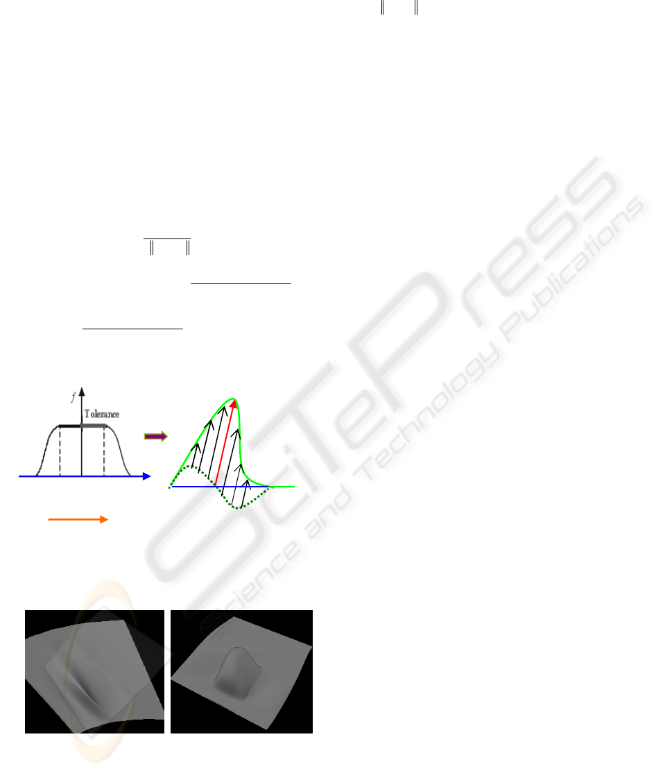
Figure 6: The force f is symmetrically distributed along
the curve; (left) the “tolerance” serves as a step; Q repre-
sents different vertex in this curve. (Right) the deformed
curve is produced by symmetrical force distribution.
Figure 7: before smoothing (left) and after smoothing
(right)
The details are shown in formula 12 where the
value
),( vuC is the length of curve C, while Np is the
number of control vertices on each curve. The toler-
ance factor is used to determine the step of the dis-
tribution, along the corresponding curve.
From formula 13, we can achieve symmetric
space deformation by symmetrically and gradually
distributing
)P
,i
K(
i
f
to different control vertex
t
Q
on
the parent surface. The results can be compared in
Figure 7.
5 EXPERIMENT AND RESULTS
We have implemented our method in C++ with
OpenGL and OpenInventor 4.0 on a Pentium 4
1.6GMhz with 512MB of RAM. This implementa-
tion provides real-time feedback (approx 20 frames
per second for average 30,000 vertices) with a se-
quence of deformations.
In order to improve the interaction for the re-
quired shape, we have developed a 3D dragger
metaphor, which can be freely controlled in 3D
space. This is used for handling the plane in which
the object lies. So that the user is capable of dynami-
cally controlling the target curve and parent models
to reproduce a series of results. Meanwhile in our
application, all the objects can be adjusted by freely
“oversketching”.
Furthermore, we apply two methods to limit the
influence of the force to the surface. The first is that
the local area is directly obtained by projecting the
target curve onto the parent model. In this way a
series of springs are produced in the parent model
which are going to respond to the energy strains
from the target curve. In the second method, we
directly define a local region by sketching a bound
curve as aforementioned. The comparison is shown
in the following figures.
Our experiments indicate that our method is in-
tuitive and effective for creating and editing a large
variety of free form shapes (see Figure 8, 9, 10).
P
f ( k
i
, p)
Deformed Curve
Original Curve
Q
j-2
Q
j-1
Q
j
Q
j+1
Q
j+2
U
ADAPTIVE CONSTRAINT AND 3D SKETCH-BASED DEFORMATION FOR INTERACTIVE FREE FORM
SURFACE STYLING
397
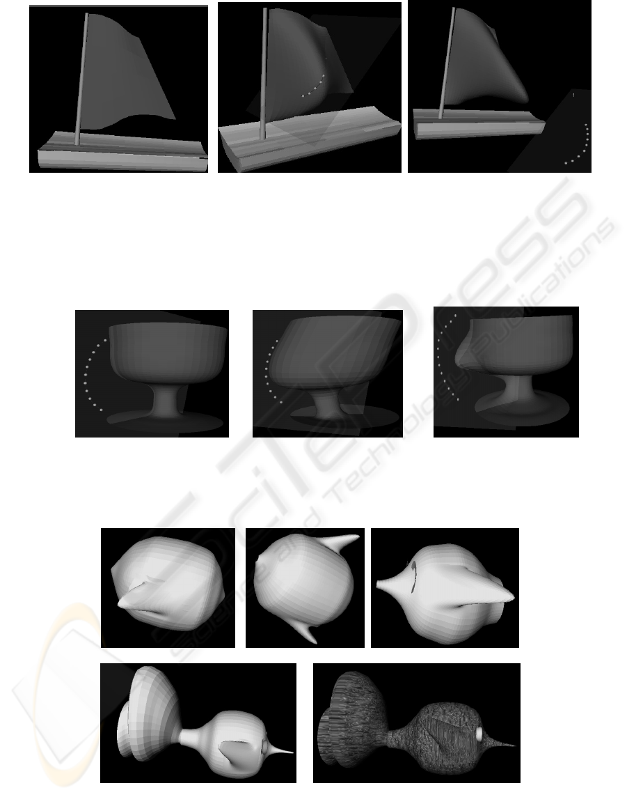
(a) (b) (c)
Figure 8: Dynamical shape control by spline-driven deformation method where the parent surfaces are respectively
generated by geom_fill, skin, and revolving. (a) The red sail is selected as the sensitive surface which is going to be
deformed. (b) The local area is automatically obtained by projecting target curve (blue spline) onto the surface.
When the target curve is close to the parent model the target curve imposes high force intensity to the local area. (c)
When the target curve is moving away from the parent model, the influenced region becomes smaller but the force
energy becomes stronger and consequently the surface will be dynamically adjusted in response to the energy dis-
tribution.
(a) (b) (c)
Figure 9: Three stages of the operation: (a) Before the deformation. (b) Without a predefined local region: the key
points in the target curve (blue balls) produce force springs in the surface and only impose strain to these sensitive
springs. However the influence can not be strictly localized. (c) With the predefined local region, the force’s in-
fluence can be well localized.
(a) (b) (c)
(d) (e)
Figure 10: (a) (b) (c) with the predefined local region we can properly control the result of the deformation. (d)
We provide interactive shape control which allows to re-deform any selected parts. (e) The texture is applied and
its mapping is dynamically changed with the user interaction.
GRAPP 2006 - COMPUTER GRAPHICS THEORY AND APPLICATIONS
398

6 CONCLUSION AND FUTURE
WORK
In this paper, we present a physical-based deforma-
tion method. When working with our deformation
method, the designer does not need to manipulate
some non-intuitive mathematical shape parameters,
such as control points and control vectors. Instead,
he/she can work with the point constraints and
spline-based constraints, therefore designers can
easily and intuitively control the resultant shape.
The potential function is centered at the con-
straint and it symmetrically distributes the so-called
force energy. Compared with other deformation
methods, this approach has the following advantages:
intuition, locality and simplification since this
method combines shape creation and deformation.
Finally, it is possible to use various intensities and
smoothing functions to enrich the quality and accu-
racy of the deformation.
Although our method is intuitive and less compu-
tationally challenging for free form surface modeling
and styling, it still needs some time to create sophis-
ticated models; and there is a limitation in our de-
formation technique when we want to change the
topology of the model, such as creating a hole.
In the future work, we will further investigate in-
telligent operations for shape editing and multi-
surfaces modeling based on 3D sketching; such as
surface splitting and stitching. We also plan to im-
prove the connectivity and continuity between dif-
ferent surfaces based on declarative constraints.
ACKNOWLEDGEMENT
This research presented in this paper is a part of EU
project “IMPROVE” and of the Part of the project
InSIDe.
REFERENCES
Barr, A. H.,1984 , “Global & local deformations of solid
primitives,” Computer Graphics, 18(3), 21-30.
Güdükbay, U. and Üzgüç, B., 1990, “Free-form solid
modeling using deformations,” Computer Graphics,
14(3/4), 491-500.
Sederberg, T. W. and Parry, R.,1986, “Free-form deforma-
tions of solid geometric models,” ComputerGraphic,
20(4), 151-160.
Coquillart, S., 1990, “Extended free-form deformation: A
sculpting tool for 3D geometric modeling,” Computer
Graphics, 24(4), 187-196.
Bechmann, D., 1994, “Space deformation models survey,”
Computer & Graphics, 18(4), 571-586.
Kalra, P., Mangili A. and Thalmann, N., 1992, “Simula-
tion of facial muscle actions based on rational free-
form deformation,” Computer Graphics Forum, 2(3),
59-69.
Lamousin, H. J. and Waggenspack, W. N., 1994, “NURBS
based freeform deformation,” IEEE Computer Graph-
ics & Applications, 14(6), 59-65.
Griessmair, J. and Purgathofer, W., 1989, Deformation of
solids with trivariate B-spline,” Proc.
EUROGRAPHICS’89, 137-148.
Coquillart S. and Jancene, P., 1991, “Animated free-form
deformation: an interactive animation technique,”
Computer Graphics, 25(4), 23-26.
Chadwick, J. E., Haumann, D. and Parent, R. E., 1989,
“Layered construction for deformable animated char-
acters,” Computer Graphics, 23(3), 243-252.
Borrel, P. and Rappoport, A., 1994, “Simple constrained
deformations for geometric modeling and interactive
design,” ACM Transactions on Graphics, 13(2), 137-
155.
Xiaogang, J., Youfu L. and Qunsheng, P. , 2000, “General
constrained deformation based on generalized meta-
balls,” Computer & Graphics, 24(2), 219-231.
Léon, J. C. and Veron, P., 1997, “Semiglobal deformation
and correction of free-form surface using a mechanical
alternative,” The Visual Computer, 13(3), 109-126.
Léon, J. C. and Trompette, P. , 1995, “A new approach
towards freeform surfaces control,” C.A.G.D, 12(4),
395-416.
Léon, J. C., 1991, “Modé lisation des courbes et des surfa-
ces pour la CFAO,” hermès, paris.
Li, Han, Giuseppe, Conti, Raffaele, De. Amicis (2005),
“Freehand 3D curve recognition and oversketching,”
Eurographics UK Chapter 2005,187-193.
Chesutet, V. and Catalano, C.E., Pernot, J. P. “ 3D
Sketching with Fully Free Form Deformation
Features for Aesthetic Design.”
EUROGRAPHICS Workshop, Sketch-based In-
terfaces and Modeling, 2004, 9-18.
Michalik, P. and Brüderlin, B.D., “Constraint-based De-
sign of B-spline Surface from Curves.” ACM Sympo-
sium on Solid Modeling and Applications, 2004, 213-
220.
DIETZ, U. , “Creation of Fair B-Spline Surface Fillets” In
Creating Fair and Shape Preserving Curves and Sur-
faces. B.G. Teubner, Stuttgart, 1998. 2, 3, 8
Fontana, M., Giannini, F., Meirana, F., “Free Form Fea-
tures for Aesthetic Design.” Int. Jou. Shape Modelling,
vol. 6, n°2, 2000, 273-302.
ADAPTIVE CONSTRAINT AND 3D SKETCH-BASED DEFORMATION FOR INTERACTIVE FREE FORM
SURFACE STYLING
399
