
SIMPLE AND FAST RAY TRACING OF POINT-BASED
GEOMETRY
Nordin Zakaria
Universiti Teknologi Petronas, Perak, Malaysia
Bahari Belaton, Abdullah Zawawi Hj Talib
School of Computer Science,Universiti Sains Malaysia,Penang, Malaysia
Keywords: Ray Tracing, Point Primitives.
Abstract: We discuss in this paper a framework for simple and fast ray tracing of point-based geometry. Our solution
requires neither implicit surface definition nor the use of non-simple rays. Points are simply treated as disk
primitives. To prevent shading artifacts due to the use of disk representation, each ray is intersected with a
few disks, and the intersection results interpolated. Further, to speed up the ray-object search, we adapt the
KD-tree with bounding spheres structure applied in the QSplat point splatting system (Rusinkiewicz and
Levoy 2000). Our prototype implementation is generally competitive compared to previous point set ray
tracers. Further it demonstrates considerable speedup over a point set ray tracer based on a conventional
KD-tree, while producing images with acceptable ray-traced quality.
1 INTRODUCTION
A point-based geometry is a geometric model
represented as a set of discrete points. Each point
stores information such as color, position and
normal value. Unlike in a triangle mesh, there is no
connectivity information stored together with the
points. Recent advances in 3D scanning
technologies, as evident in the Digital Michelangelo
project (Levoy et al 2000), have led to the creation
of models each represented by millions to hundreds
of millions of points. Due to the size, it is nontrivial
to convert such data set to polygon-based or other
geometric representation schemes. Hence, directly
using the sampled point set for rendering and
modeling purposes is an alternative pursued by
several research groups in recent years.
The approach more commonly used to directly
view a point-based geometry is splatting (Pfister et
al 2000, Zwicker et al 2001). In splatting, the basic
idea is to iterate through the points in the point set
and compute its projection onto the screen. A
splatting-based point set viewer, examples of which
include QSplat (Rusinkiewicz and Levoy 2000) and
Pointshop (Zwicker et al 2002), can typically run at
an interactive frame rate on a computer system with
more recent consumer graphics hardware. While, it
is fast and easy to view a point-sampled geometry
using splatting, it is nontrivial and expensive, using
the technique, to create advanced accurate lighting
effects such as shadows and self-shadowing,
reflection, and global illumination. On the other
hand, ray tracing, being based on the simulation of
light rays through a 3D environment, can quite
easily model such effects. Further, ray tracing is
easy to parallelize and has been shown to scale well
with increasing data size (Wald et al 2001). Such
scalability is not true for splatting.
However, there is a fundamental issue in
applying ray tracing to a point set. A point,
mathematically, has neither volume nor area. A ray
is thin. Hence, the chance of a thin ray hitting a
mathematical point is practically nil. To the best of
our knowledge, there have been four major works
that investigate the ray tracing of point-based
geometry and dealt with this problem. Adamson et al
(2003) and Wald and Seidel (2005) blend individual
points within a small neighborhood to form local
implicit surfaces. Wand et al (2003) use cone ray
instead of thin ray. Schaufler and Jensen (2000)
trace cylinders (instead of thin ray), and compute the
intersection depending on the local density of the
points along the "ray". We do not use local implicit
293
Zakaria N., Belaton B. and Zawawi Hj Talib A. (2006).
SIMPLE AND FAST RAY TRACING OF POINT-BASED GEOMETRY.
In Proceedings of the First International Conference on Computer Graphics Theory and Applications, pages 293-298
DOI: 10.5220/0001352702930298
Copyright
c
SciTePress
surface as this would be a sort of conversion from
points to another data structure. In other words, the
data structure and the intersection process would not
be simple anymore. Also, we choose not to use cone
rays and cylindrical rays as they are both more
expensive than thin rays. Further, the outcome of
cylindrical-ray intersection test with a point set to
some extent depends on the ray direction.
Another issue in applying ray tracing to a point-
based geometry is the sheer size of typical point-
based data set. A spatial data structure needs to be
imposed on the point set. Schaufler and Jensen
(2000) reported on the use of octree for their ray
tracing of point-based geometry. Wand et al (2003)
discuss on a multiresolution hierarchy that contains
both points and triangles. Wald and Seidel (2005) go
in depth into the KD-tree data structure that they use
for their own work. The advantage of using KD-tree,
as noted by Havran (2001), is that it adapts
particularly well to a scene that contains large
sections of empty space, such as one composed of
surface-represented or point-sampled objects.
Hence, it is natural to consider this data structure for
our work here.
Given the issues involved in applying ray tracing
to point-based geometry, the research questions we
wish to address in this paper can be formulated as
follows:
- Is there a better method for intersecting a
ray with point primitives? Such a method
would have these properties: simple to
implement, and fast.
- Can KD-Tree, being the data structure we
consider most appropriate for our work
here, be adapted for faster ray traversal of
point set?
Our contribution in this paper is a framework for
ray tracing of point-based geometry that addresses
both of the above research questions. The
framework attempts to answer the first question by
refining the approach adopted by Schaufler and
Jensen (2000). Specifically, it eliminates the need
for cylindrical rays, but follows much of the rest of
their approach. Further, the framework attempts to
answer the second research question by adapting the
KD-tree with bounding spheres as applied in the
QSplat point-splatting system. In all, our framework
maintains the discrete nature of point-based
geometry, is easy to implement, and has a
performance competitive with that reported in
previous works.
2 APPROACH
We start with the assumption that we have only a
few point primitives, P
1
..P
4
, to intersect the ray with.
When many more points are actually available to
intersect with, we use a spatial data structure to
reduce the number of intersection tests required.
Each point, being derived from a scanning process,
actually represents a small area. Hence, we consider
each point, P
i
, to be a disk, the center of which is at
position p
i
. The disk has a certain radius, r
i
, and a
certain normal, N
i
. Typically this normal is acquired
from the scanning process. It could also be
computed as described in (Pauly 2002).
2.1 Ray-Point Intersection
A disk representing a point P has a certain plane
associated with it. The equation of a plane is given
by:
0
=
+
+
+
DzNyNxN
zyx
The parametric form of a ray r is given by:
η
≤
≤
+
=
ttdotr 0,)(
where o is the ray's origin, d the direction
vector, and t the parameter
The standard ray-plane intersection calculation
computes t as follows:
η
≤
≤
+
=
ttdotr 0,)(
Substituting t into the parametric form of the ray,
we obtain a positional value, I. We check the
distance, s, between I and p
i
. If s > r
i
, there is no
intersection with the disk representing the point P.
If we stop at the first disk that the ray hit, we’ll
have the same problem encountered by Wald and
Seidel (2005). They reported that their first attempt
has been to intersect a thin ray with disk-represented
point primitives. Disks were seen sticking out,
especially at curved area. We note that the cause of
this problem is that the area representing each point
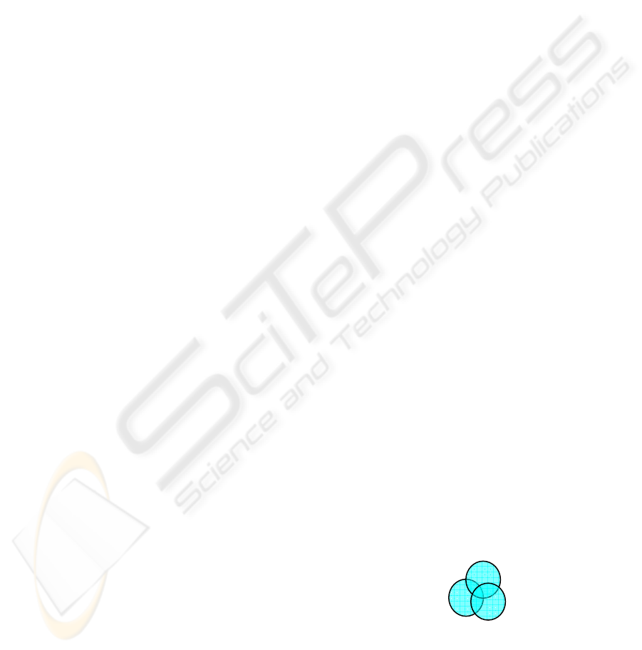
actually overlaps, as shown in Figure 1.
Figure 1: Points as overlapping disks.
To solve the problem, we intersect the ray with
each of the point primitives, P
1
…P
4
. We then
interpolate the intersection results (eg. position,
normal) according to the following weighing scheme
used by Schaufler and Jensen (2000):
GRAPP 2006 - COMPUTER GRAPHICS THEORY AND APPLICATIONS
294
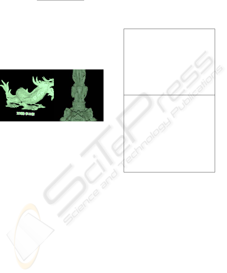
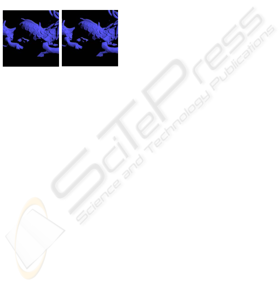
Our intersection algorithm can successfully
display a point-sampled geometry such that it
appears to comprise of continuous surfaces. Two
example images are shown in Figure 2. More images
are in Figure 9.
Of course, a point-sampled geometry typically
consists of millions of points, not just a few. In this
paper, we use a tree data structure to cut down on
the number of points a ray actually needed to be
tested against.
Figure 2: Ray Tracing of Point-Sampled Dragon and
Statue.
2.2 Ray Traversal
For efficient ray traversal, we adapt the bounding
sphere hierarchy used in Rusinkiewicz and Levoy
(2000). This data structure is basically just a KD-
tree; the fundamental distinction from the usual KD-
tree being that a bounding sphere is computed at
each node in the tree and used for backface culling
and level of detail (LoD) selection in the context of
point splatting.
There has been other works on multiresolution
point representations, notably that by Chen and
Nguyen (2001) and (Wand et al 2003). However, the
approach in QSplat is closest to the approach
presented in this paper.
We use the same algorithm as used in QSplat to
build up the bounding sphere hierarchy. As the tree
is built up, properties at interior nodes are set to the
average of these properties in the subtrees. As in
QSplat, in our current implementation, tree
construction is based on axis-aligned bisections;
hence currently the resulting tree is not guaranteed
to be complete and balanced.
Our tree-traversal algorithm has a structure
similar to that used in the QSplat. Figure 3 shows
both algorithms. However, there is a fundamental
difference in the detail; when the projection of a
bounding sphere onto an image plane is small
enough, we intersect our ray not against a single
splat or disk centered at the current node. Instead, to
Figure 3 : a) QSplat's traversal algorithm, b) our traversal
algorithm.
avoid disk-related rendering artifacts, we intersect it
against the children in the node and interpolate the
intersection results as discussed in section 2.1.
2.2.1 Optimizing using LoD and Backface
Culling
QSplat bases tree recursion decision on projected
sphere size of current node. A node is subdivided if
the area of its bounding sphere when projected onto
the image plane is greater than a threshold. Hence,
Level of Detail (LoD) generation is automatic with
different viewpoint. We adapt this idea for our ray
tracer. Key to efficient implementation of this
optimization technique is fast computation of the
projected size of a sphere on the image plane. To do
this computation, we assume the viewing setup as
shown in Figure 4 for our ray tracer.
a) TraverseHierarchy(node) {
if (node not visible)
skip this branch of the tree
else if (node has no grandchildren)
draw all primitives in node as splats
else if (benefit of recursing further is
low)
draw a splat
else
for each child in children (node)
TraverseHierarchy(child)
}
b) TraverseHierarchy(node) {
if (node not visible)
skip this branch of the tree
else if (node has no grandchildren)
intersect ray against point primitives
in the node
else if (benefit of recursing further is
low)
intersect ray against children of
current node
else
for each child in children (node)
TraverseHierarchy(child)
}
∑
∑
−
−
=
i
i
i
i
i
pI
pIattrib
attrib
||||
||||
SIMPLE AND FAST RAY TRACING OF POINT-BASED GEOMETRY
295
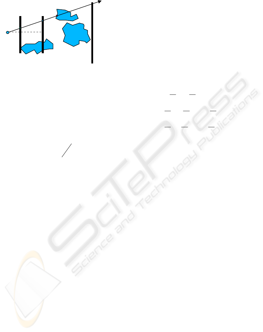
Figure 4: Viewing setup.
We compute the projected size of a bounding
sphere as follows: For a given ray, we first intersect
it with the image plane to find t
1
, the ray parameter
at the intersection. Next, when we reach a node in
our tree data structure, we compute the projection, t
2
,
of the bounding sphere center onto the ray. Let the
diameter of the sphere be L. Using similar triangle,
we then compute the projection size, L
1
, of the
sphere on the image plane as follows:
L
1
is then scaled according to the resolution of
the screen device, and is used to determine whether
a bounding sphere is far enough so as not to warrant
further recursion.
As in QSplat, we use the normal and normal
cone information stored in a node in our tree to
determine whether the entire subtree represented by
the node can be eliminated. If cone faces entirely
away from the viewer, the node and its subtree are
discarded. And if for a node, its cone points entirely
towards the viewer, there is no need to test its
children for backface culling.
2.2.2 Optimizing by Using Bounding Box
Instead of Using Bounding Sphere
A sphere-shaped bounding volume is natural for
point set rendering with LoD. But we would only
process a bounding sphere directly as a terminating
node when the sphere projection is small enough.
This would only happen, for camera-object distances
below a certain limit, when we are low enough in the
tree. Generally, however, a bounding box is tighter.
The intuition here, is hence, to use a tighter
bounding volume closer to the top of the tree. A
simple informal analysis strengthens the basis of this
intuition.
Consider a binary tree. Let A be an interior node.
Let the children nodes be B and C. Let the children
nodes of B be D and E, and that of C be F and G.
The overall cost, t
A
, of intersecting a ray against the
node A is
where c
A
is the cost of traversing node A, and t
B
and t
C
are the cost of processing node B and C
respectively and p
B
and p
C
are the probabilities that
the ray passes through the nodes B and C
respectively.
From geometric probability, since a sphere is a
convex volume,
where s
A
, s
B
, and s
C
are surface areas of sphere
A, B and C respectively.
Let N
B
and N
C
are the number of children in B
and in C respectively. Expanding (1),
What we can intuitively infer after a few lines of
expansion is that the ray shooting cost is dominated
by the cost of shooting the ray against higher-level
nodes of the tree. Hence, it suffices to use bounding
boxes at higher levels in the tree. This should lead to
better performance. In fact, we confirm on this in the
next section.
3 IMPLEMENTATION AND
RESULTS
We implemented our code in C++ as a plug-in for a
modified PBRT, an educational freeware ray tracer
(Pharr and Humphreys 2004). Compilation was on a
Pentium PC running on Linux with the O2 flag used.
However, our actual coding stands to be further
optimized, especially to take advantage of memory
cache optimization or CPU-specific SIMD
instructions as has been done by Wald and Seidel
(2005).
The primary point-sampled models that we play
with for the data in this section are the dragon and
statue shown in Figure 1. The dragon comprises of
3,609,600, while the statue comprises of 4,999,996
points. It takes 700 ms to build the hierarchy for the
ray.direction
r
ay.origin
far plane
image plane
pixel
ij
camera
intersecti
2
1
1
t
t
LL =
)1(⋅⋅⋅++=
ccbBAA
tptpct
ACC
ABB
ssACpp
ssABpp
/)|(
/)|(
==
=
=
...)()(
...))()((
)()(
11
11
++++=
++++=
++=
∑∑
∑∑
==
==
d
i
d
i
d
i
d
i
N
i
e
A
E
N
i
d
A
D
B
A
B
A
N
i
e
B
E
N
i
d
B
D
B
A
B
A
C
A
C
B
A
B
AA
t
S
S
t
S
S
c
S
S
c
t
S
S
t
S
S
c
S
S
c
t
S
S
t
S
S
ct
GRAPP 2006 - COMPUTER GRAPHICS THEORY AND APPLICATIONS
296
dragon model, and 1,022 ms for the statue model.
The resulting hierarchy data structure comprises of
5,365,234 points for the dragon, and 7,468,783
points for the statue, implying a nodes-to-points
ratio of approximately 1.4. The maximum depth in
both trees is 17.
For the actual rendering, we look for
performance advantage from the use of the bounding
sphere hierarchy. We employ for each run a total of
665,911 and we use an image resolution of 400 by
400 pixels to generate the images as shown in Figure
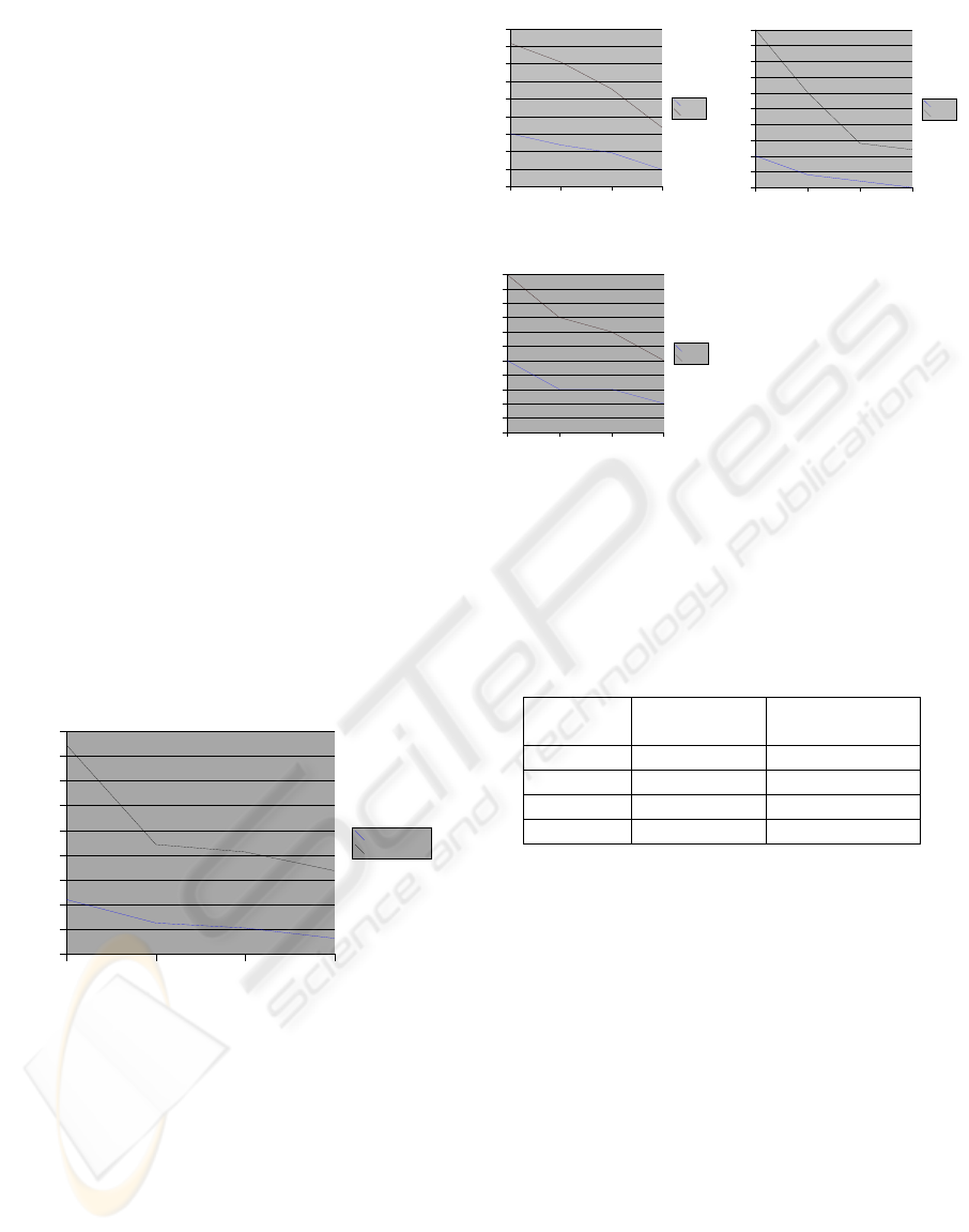
1. As shown in Figure 5, with a conventional KD-
tree, tree traversals takes approximately 420 s for the
statue model, and 110 s for the dragon model. With
the inclusion of codes for LoD, traversal time for the
statue drops to about 220 s, while that for the dragon
drops to about 60 s. With inclusion of backface
culling, traversal time for the statue drops to about
200 s, while that for the dragon drops to about 50 s.
Finally with the inclusion of box-shape bounding
volume higher in the tree, the traversal time for the
statue drops to 160s and that for the dragon drops to
about 32s. Hence, the overall improvement from a
standard KD-tree, for the data set that we experiment
with, is in the range between 60% and 70%. Note
that due to the limited number of data set that we
experimented with, this number is only rough.
However, it does indicate the performance
improvement that one can expect from the bounding
Figure 5: Ray traversal time.
sphere hierarchy algorithm outlined in this paper.
The drop in traversal time follows the drop in the
average number of nodes visited, average number of
disk-ray intersections and the average maximum
depth traversed by a ray. The decrease in these
numbers are shown in Figure 6. Overall drop in
average number of node visited by a ray is between
60% and 70%. The drop in the average number of
ray-disk intersections is about 70%, while the drop
in the average maximum depth traversed by a ray is
in the range between 50% and 60%.
Figure 6: Graphs showing drop in avg # nodes visited,
avg. # disk-ray intersection and max depth visited.
Taking our experimentation further, we perform
a sequence of rendering of the dragon model with
increasing distance from the camera. We do the
rendering sequence twice, once with LoD on and
once with LoD off. As shown in Figure 7, the result
using our hierarchy structure is consistently better
compared to that using just a KD-tree.
Distanc
e
Time (s)
with No LoD
Time (s)
with LoD
350 158.1 126
550 146.0 69.4
750 103.2 45.1
1500 80.1 20.1
Figure 7: Traversal time for dragon with varying distance.
We note, however, despite the drop in traversal
time, traversal still takes up about 85% of the
rendering time. Hence, more work should be done to
further improve the performance of the algorithm.
The performance data reported in this paper is,
of course, not entirely comparable with that reported
in other papers; there are differences in coding,
camera viewpoint, CPU, data sets, ray generation
policy, image resolution, etc. We can however make
a (very) rough comparison. Schaulfler and Jensen
(2000) ray traced a 543,652-points Buddha model in
36 s. Anderson and Alexa (2003) takes “several
hours” even for a 150,000-points data set. We render
a 3,609,600-points Dragon model in full view in
under 32 s. Still then, Wald and Seidel (2005),
however, using highly-tuned SIMD memory-
optimized code and dual processors, achieve 5
frames per second for a 1,309,059 Dragon model.
Hence, one conclusion that we can make here is that
OnlyKDTree Lod LoD+Culling LoD+Culling+
BBox
0
3
5
8
10
13
15
18
20
23
25
Average # Disk
Dragon
Statue
OnlyKDTree Lod LoD+Culling LoD+Culling+
BBox
0
25
50
75
100
125
150
175
200
225
Average # Nodes
Dragon
Statue
OnlyKDTree Lod LoD+Culling LoD+Culling+
BBox
0
1
2
3
4
5
6
7
8
9
10
11
Average Maximum Depth
Dragon
Statue
OnlyKDTree Lod LoD+Culling LoD+Culling+B
Box
0
50
100
150
200
250
300
350
400
450
Traversal Time (s)
Time (Dragon)
Time (Statue)
SIMPLE AND FAST RAY TRACING OF POINT-BASED GEOMETRY
297
our implementation performance is competitive
compared to that of other single-CPU
implementations.
Apart from performance aspects, we consider as
well rendering quality. Despite the discrete nature of
the surface representation, rendering quality is quite
high. Artifacts where visible along the silhouette are
due primarily to the multisampling code that we use
in our program, rather than due to the representation
or the algorithm that we use. Figure 8 shows 2
images of the dragon model, one with LoD on and
the other off.
Figure 8: Rendering with and without LoD.
4 CONCLUSION
We have discussed a framework for ray tracing of
point-based geometry. The framework addresses two
issues: how to intersect a ray with a point set, and
how to accelerate the ray-object search. Our solution
is simple to implement, as it requires neither
conversion to implicit surfaces nor tracing of non-
simple ray. Further, it shows a performance
competitive with that of other point-set ray tracer,
and produces images with acceptable ray-traced
quality.
Of course, more work remains to be done to
strengthen the research presented in this paper. We
would like to do more analysis on the optimizations
that we have presented in this paper. One particular
question we would like to have answered is: how to
determine the level in the hierarchy starting from
which we should use sphere-shape bounding volume
(rather than box-shape volume). We would also like
to investigate ways to improve memory usage and
memory cache performance, and to investigate
alternative ways, apart from looking at projected
sphere size, to decide on whether or not to recurse
further in the ray traversal of the hierarchy structure.
REFERENCES
Adamson A., Alexa M: Ray Tracing Point Set Surfaces. In
SMI’03:Proceedings of the Shape Modeling
International 2003 (2003), pp.272.
Chen B., Nguyen M.X. Pop: A Hybrid Point and Polygon
Rendering System for Large Data. In IEEE
Visualization 2001 (2001), pp. 45-52.
Coconu L., Hege H.-C.: Hardware-Accelerated Point-
Based Rendering of Complex Scenes. In Proceedings
of the 13
th
Eurographics Workshop on Rendering
(2002), pp. 43-52.
Havran V.: Heuristic Ray Shooting Algorithms. PhD
thesis, Faculty of Electrical Engineering, Czech
Technical University in Prague, 2001.
Levoy M., Pulli K., Curless B., Rusinkiewicz S., Koller
D., Pereira L., Ginzton M., Anderson S., Davis J.,
Ginsberg J., Shade J., Fulk D.: The Digital
Michelangelo Project: 3D Scanning of Large Statues.
In Proc. Of ACM SIGGRAPH (2000), pp. 131-144.
Pauly M. Gross M.: Efficient Simplification of Point-
Sampled Surfaces. In Proceedings of the Conference
on Visualization '02 (2002), pp. 163-170.
Pfister H., Zwicker M., van Baar J., Gross M.: Surfels:
Surface Elements as Rendering Primitives. In Proc. Of
ACM SIGGRAPH (2000), pp. 335-342.
Pharr M., Humphreys G.: Physically Based Rendering:
From Theory to Implementation., 2004, Elsevier.
Rusinkiewicz S., Levoy M.:QSplat: A Multiresolution
Point Rendering System for Large Meshes, In Proc.
Of ACM SIGGRAPH (2000), pp. 343-352.
Schaufler G., Jensen H.W.: Ray Tracing Point Sampled
Geometry. In Proceedings of the Eurographics
Workshop on Rendering Techniques (2000), pp. 319-
328.
Wald I.: Realtime Ray Tracing and Interactive Global
Illumination. PhD thesis, Computer Graphics Group,
Saarland University, 2004.
Wald I., Seidel H.-P., Interactive Ray Tracing of Point-
Based Models, In Proceedings of Symposium on Point
Based Graphics, 2005.
Wand M., Strasser W.: Multi-Resolution Point-Sample
Raytracing. In Graphics Interface 2003 Conference
Proceedings (2003).
Zwicker M., Pfister H., van Baar J., Gross M.: Surface
Splatting. In Proc. Of ACM SIGGRAPH (2000), pp.
371-378.
Zwicker M., Pauly M., Knoll O., Gross M.: Pointshop
3D: An Interactive System for Point-Based Surface
Editing. In Proc. Of ACM SIGGRAPH (2002), pp.
322-329.
GRAPP 2006 - COMPUTER GRAPHICS THEORY AND APPLICATIONS
298
