
AN EFFICIENT TEXTURE GENERATION TECHNIQUE FOR
HUMAN HEAD CLONING AND MORPHING
Yu Zhang
Department of Computer Science, School of Computing
National University of Singapore, Singapore 117543
Keywords:
Head modeling, texture mapping, real-time rendering, morphing, model adaptation.
Abstract:
This paper presents a technique to efficiently generate a parameterized full-head texture from a single face
image of the scanned data for modeling photorealistic 3D heads. We automatically register face scans in a
database by deforming a generic head mesh to fit the specific person’s face geometry with a volume morphing
approach. After the face texture is transferred onto it, the 3D generic mesh is parameterized over a 2D texture
domain to establish a correspondence between all the scanned textures. After having performed a vertex-to-
image binding for all vertices of the head mesh, we automatically generate a full-head texture using color
interpolation for unbound regions and weighted average splines for visual boundary removal. We also use
a deformation method to extract ear textures from the input image for texturing individual ears. With the
exception of the initial feature point selection, our method is fully automated. We show photorealistic and
real-time head rendering and morphing with the resulting texture.
1 INTRODUCTION
Among the tasks of reproducing the complexity of
the face in the computer, rendering is crucial for gen-
erating visually convincing appearance of a particu-
lar person’s face. Basic rendering algorithms include
polygonal shading (flat shading, Gouraud shading and
Phong shading), ray tracing and radiosity. However,
facial skin has reflectance properties that are not mod-
eled well by these widely-used shading models: the
produced facial image appears plastic and cartoon-
like with a too-smooth surface.
For sheer photorealism, texture mapping is a pop-
ular technique to get a better rendered image. With
a significant increase in the quality and availability
of 3D capture methods, a common approach towards
creating face models of real humans uses laser range
scanners to accurately acquire both the face geometry
and texture. One limitation of the scanner technol-
ogy, however, is that the complete head geometry can
not be easily captured as the hair in dark color absorbs
all of the laser radiation. The top and back of the head
are generally not digitized unless the hair is artificially
colored white or the subject wears a light-color cap,
but that destroys the texture. In most cases, only the
frontal face can be properly textured. There is no au-
tomatic mechanism provided to generate a full-head
texture from the acquired single frontal-face image
for realistic rendering towards a “cloned” head.
In this paper, we present a technique to efficiently
generate a parameterized full-head texture for model-
ing heads with a high degree of realism. We start with
a generic head model with a known topology. It is
deformed to fit the face scan of the particular human
subject using a volume morphing approach. The fa-
cial texture associated with the scanned geometry is
then transferred to the original undeformed generic
mesh. We automatically construct a parameteriza-
tion of the 3D head mesh over a 2D texture domain,
which gives immediate correspondence between all
the scanned textures via a single, prototype layout.
After having performed a vertex-to-image binding for
vertices of the head mesh, we generate a cylindrical
full-head texture from the remaining parameterized
texture of the face area. We also address the creation
of individual textures for ears. Apart from an initial
feature point selection for the texturing, our method
works automatically without any user interaction.
Our main contribution is a technique that uses a
frontal-face image of the scanned data to generate
a full-head texture for photorealistic rendering and
morphing with minimal manual intervention. This
includes the new algorithms to automatically para-
267
Zhang Y. (2006).
AN EFFICIENT TEXTURE GENERATION TECHNIQUE FOR HUMAN HEAD CLONING AND MORPHING.
In Proceedings of the First International Conference on Computer Graphics Theory and Applications, pages 267-275
DOI: 10.5220/0001352202670275
Copyright
c
SciTePress

meterize textures of a set of unregistered face scans
to establish the mapping correspondence, to robustly
produce individual full-head skin texture, and to effi-
ciently create ear textures from a single input image.
This paper is organized as follows. Section 2 re-
views the previous work. Section 3 presents the face
data we use. Section 4 describes the model adapta-
tion process. The approaches to mesh parameteriza-
tion, full-head texture synthesis, and creation of ear
textures are elaborated in Section 5. We show exper-
imental results in Section 6. Section 7 concludes by
discussing future work.
2 PREVIOUS WORK
Beginning with Parke’s pioneering work (Parke,
1972), desire for improved realism has driven re-
searchers to extend geometric models (Parke, 1982;
Thalmann et al., 1989) with physically-based models
which attempt to model the influence of muscle con-
traction onto the skin surface by approximating the
biomechanical properties of skin (Kahler et al., 2002;
Lee et al., 1995; Platt and Badler, 1981; Terzopoulus
and Waters, 1990; Waters, 1987). Physically-based
models with layered anatomical structure were com-
bined with non-linear finite element methods (Koch
et al., 1996) in systems that could be used for plan-
ning facial surgeries. Free-form deformations have
been employed in (Kalra et al., 1992) to manipu-
late facial expressions. In parallel, Williams presents
a compelling argument (Williams, 1990) in favor of
performance-driven facial animation, which antici-
pated techniques for tracking head motions and facial
expressions in video (Essa and Basu, 1996; Pighin
et al., 1999). In performance-driven approaches, col-
ored markers painted on the face are extensively used
to aid in tracking facial motion (Guenter et al., 1998).
A more expensive alternative could use a 3D scanning
technique (Zhang et al., 2004a), if the performance
can be re-recorded with such a system.
A variational approach is presented in (DeCarlo
et al., 1998) to create a range of static face models
with realistic proportions. They use anthropometric
measurements, which constrain the deformation of a
B-spline generic head model. Pighin et al. (Pighin
et al., 1998) combine 2D morphing with 3D transfor-
mations of the geometric model to produce photore-
alistic facial animation. In addition, Blanz and Vetter
(Blanz and Vetter, 1999) present a process for esti-
mating the shape of a face in a single photograph, and
a set of controls for intuitive manipulation of appear-
ance attributes (thin/fat, feminine/masculine).
Texturing in the context of face modeling is, how-
ever, an often neglected issue. Williams (Williams,
1990) presents an approach to generate and register
a texture map from a peripheral photograph. This ap-
proach is meanwhile superseded by the ability of laser
scanners to acquire geometry and texture in one step
(Lee et al., 1995; Waters and Terzopoulos, 1991). The
method presented in (Blanz and Vetter, 1999) gener-
ates an individual face geometry and texture by linear
combination of face geometries and textures from a
large database. Marschner et al. (Marschner et al.,
2000) describe a technique that uses several input
photographs taken under controlled illumination with
known camera and light source locations to generate
an albedo texture map of the human face along with
the parameters of a BRDF.
Several image-based approaches (Akimoto et al.,
1993; Guenter et al., 1998; Lee and Thalmann, 2000;
Liu et al., 2001; Pighin et al., 1998) use a small num-
ber of input photographs (or video streams) for the re-
construction of both geometry and texture. Although
they could potentially yield a higher texture quality
compared to the scanned textures, they typically suf-
fer from a less accurate geometry reconstruction and
limited animation. Generating high-resolution tex-
tures for facial skin and eyes and teeth from several
uncalibrated photographs of a person’s head has been
addressed in (Tarini et al., 2002). In their method, the
geometry of the head is acquired using a structured-
light range scanner. The photographs are registered
and combined into a single texture suitable for mip-
mapping based on the multiple textures blending tech-
nique (Rocchini et al., 1999). In contrast, not requir-
ing separate camera setups, we synthesize a full-head
texture from a reflectance image acquired by a laser
scanner which captures color of only the face area.
3FACEDATA
We use a database that contains laser scans of 186 hu-
man faces (126 male and 60 female). Each subject is
captured wearing a bathing cap and with a neutral ex-
pression (see Fig. 2). The laser scans provide face
structure data (see Fig. 1 (a)) and RGB-color val-
ues that are stored in a 360× 524 image with 8 bit
per channel (see Fig. 1 (b)). The image is registered
against the range data and can be used for texture-
mapping (see Fig. 1 (c)). We use a generic model
created with Alias|Wavefront to resemble an average
human head. It consists of 2,632 vertices and 5,221
triangles. Prescribed colors are added to each triangle
to form a smooth-shaded surface (see Fig. 1 (d)).
We have interactively specified 83 feature points on
scanned face geometry. Our generic model is already
tagged with the same feature points by default. The
feature points are located around the eyes, eyebrows,
nose, mouth and chin (see Fig. 1). In the following,
the feature points on the generic head model are de-
GRAPP 2006 - COMPUTER GRAPHICS THEORY AND APPLICATIONS
268
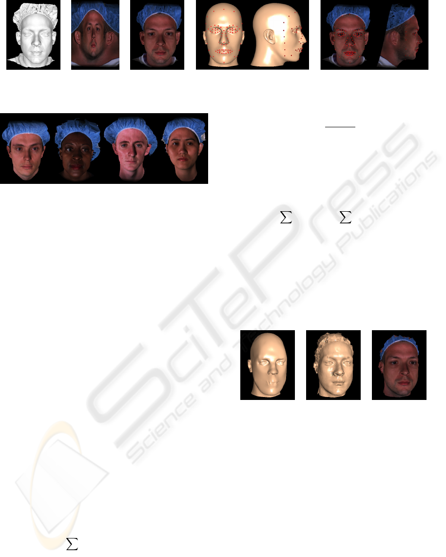
(a) (b) (c) (d) (e)
Figure 1: Face data: (a) scanned face geometry; (b) acquired color image; (c) texture-mapped face scan; (d) and (e) feature
points specified on the generic model and face scan, respectively.
Figure 2: Some exemplar 3D data of the face database.
noted as the source feature points, whereas those on
the scanned surface are called target feature points.
4 MODEL ADAPTATION
4.1 Global Warping
The global warping is based on manually specified
corresponding feature point on the generic model and
the scanned data. Denote two sets of correspond-
ing 3D points given by s
i
and t
i
(i =1,...,n)as
the source and target feature points, respectively. We
need to find a function f that maps the s
i
to the t
i
:
t
i
= f(s
i
) i =1,...,n (1)
The goal is to construct a smooth interpolating
function that expresses the deformation of the non-
feature vertices in terms of the changes in the feature
points during morphing. This problem is addressed
by scattered data interpolation methods. Radial Basis
Functions (RBFs) are a popular means of scattered
data interpolation. The interpolant using RBFs is a
function that utilizes the known displacement of each
feature point and returns the displacement value for
each non-feature point that takes it from the original
position to its position in the target form. Such a map-
ping can be expressed by a weighted linear combi-
nation of n basic functions φ
i
defined by the source
feature points and an explicit affine transformation:
f(s)=
n
i=1
c
i
φ
i
(s − s
i
)+Rs + t (2)
where s ∈R
3
is a vertex on the generic model, c
i
∈
R
3
are (unknown) weights, ·denotes Euclidean
distance, R ∈R
3×3
adds rotation, skew, and scaling,
and t ∈R
3
is a translation component. Many differ-
ent functions for φ(r) have been proposed (Nielson,
1993). We evaluated several functions including the
multi-quadric φ(r)=
r
2
+ ρ
2
, the thin-plate spline
φ(r)=r
2
log(r), the Gaussian φ(r)=exp(−ρr
2
),
and the biharmonic φ(r)=r. We had better results
visually with the multi-quadric function.
To remove affine contributions from the weighted
sum of the basic functions, we include the additional
constraints
n
i=1
c
i
=0,
n
i=1
c
T
i
s
i
=0 (3)
The system of linear equations (Eq. 1 and 3) is solved
for the unknowns R, t, and c
i
using a standard LU
decomposition with pivoting, to obtain the final warp
function f. This function can then be used to trans-
form a vertex s in the volume spanned by the feature
points. Fig. 3 (a) shows the shape of the head model
after having interpolated the 3D displacements at 83
feature points and applied them to the entire head.
(a) (b) (c)
Figure 3: Adaptation of the generic model to scanned data:
(a) source model after global warping; (b) final mesh geom-
etry after local deformation; (c) textured.
4.2 Local Deformation
The global warping with a small set of initial corre-
spondences does not produce a perfect surface match.
We further improve the shape using a local deforma-
tion which ensures that all the generic mesh vertices
are truly embedded in the scanned surface. The local
deformation is based on the closest points on the sur-
faces of the generic model and the scanned data. The
polygons of the generic model are displaced towards
their closest positions on the surface of the scanned
data. The polygons of the scanned data are organized
into a Binary Space Partition tree in order to speed up
the process of the closest point identification.
AN EFFICIENT TEXTURE GENERATION TECHNIQUE FOR HUMAN HEAD CLONING AND MORPHING
269
After the model fitting, texture from the reflectance
image is applied to the deformed generic model. As
each vertex on the fitted generic mesh samples a
scanned point, it takes the texture coordinates asso-
ciated with that point. Fig. 3 (b) and (c) show the
results of smoothly shading and texture mapping.
5 TEXTURING A HEAD
5.1 Mesh Parameterization
Our head skin texture is generated from the acquired
color image, as shown in Fig. 1 (b). One of our
goals is to readily generate 2D texture metamorpho-
sis for head morphing. In general, morphing be-
tween two images requires pairwise correspondences
between image features. In our case, however, cor-
respondences between the two textures are implicit
in the texture coordinates of the two associated face
meshes. Since every face generated from one generic
model has a similar characteristic for texture coordi-
nates, we can produce shape free face texture images
by constructing a parameterization of the 3D generic
mesh over a 2D image plane.
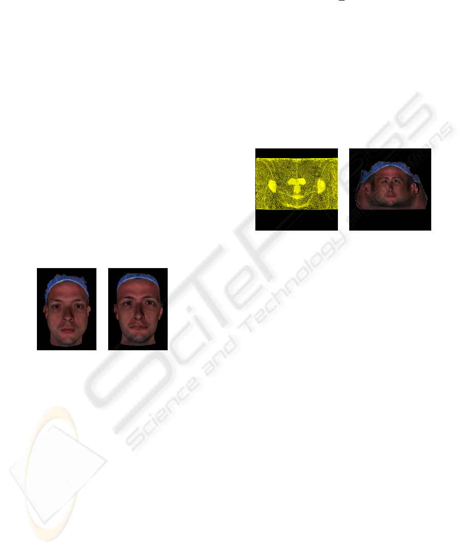
(a) (b)
Figure 4: (a) Textured adapted generic model. (b) Texture
transferred to the undeformed generic model.
Given the vertex-wise correspondence between the
adapted generic head mesh and the original unde-
formed generic mesh, it is trivial to transfer a texture
map between this pair of meshes. Each vertex on the
original generic mesh simply takes the texture coordi-
nates of its corresponding vertex on the adapted mesh.
Fig. 4 shows the texture transferred from the adapted
generic model onto the original undeformed mesh.
We want to parameterize the 3D generic head mesh
over a 2D domain [0, 1]
2
in order to obtain a sin-
gle texture map for the whole mesh. We implement a
cylindrical projection which is preferable for regions
corresponding to a volumetric surface. A cylindrical
triangular mesh corresponding to the generic model is
constructed on a virtual cylinder enclosing the model.
The projection results in a cylindrical face mesh (see
Fig. 5 (a)). Each vertex of the 2D cylindrical mesh has
cylindrical coordinates with corresponding longitude
(0-360 degrees) along the x-axis and vertical height
along the y-axis. The mapping of world coordinates
x =(x, y, z) to 2D cylindrical coordinates (u, v) uses
u =tan
−1
(
x
z
),v= y (4)
The resulting (u, v) coordinates map to a suitable as-
pect and resolution image (512×512 in our experi-
ment). We also map the original generic mesh ren-
dered with transferred texture to the image plane us-
ing the same cylindrical projection. The result is
a 512×512 cylindrical texture image in which each
pixel value represents the surface color of the texture-
mapped face surface in cylindrical coordinates (see
Fig. 5 (b)). The generic face mesh can be textured
by this cylindrical texture image using normalized 2D
cylindrical coordinates as the texture coordinates.
(a) (b)
Figure 5: (a) Texture mesh parameterization. (b) Cylindri-
cal texture image.
5.2 Synthesizing A Full-Head Skin
Texture
After having created the 2D texture mesh from the
3D generic head mesh, we perform a vertex-to-image
binding for all vertices of the 3D head mesh. This
step is carried out by taking into account removal of
undesired textures of cap and dark hair. A vertex on
the generic mesh is bound to the input image, if it
samples the scanned surface and takes valid texture
coordinates of the sampling point in the model adap-
tation procedure. Removal of cap and hair textures is
done by unbinding the vertices with a color too dis-
similar to the color of the forehead. We compute the
average color and standard deviation of the vertices in
the forehead and unbind those vertices that are at least
λ times the standard deviation away from the average.
The parameter λ should be chosen within [1.5,3], as
it empirically proved to remove the problematic (cap
and hair) textures in most cases. Fig. 6 shows the re-
maining texture with 2D mesh parameterization and
its vertex binding visualized with color coding.
Let =(x
1
, x
2
, x
3
) denote a triangle of the face
mesh and
˜
=(
˜
x
1
,
˜
x
2
,
˜
x
3
) be the corresponding tri-
angle in the texture mesh. For each triangle , one of
the following situations might occur (see Fig. 6 (b)):
1. There is a texture patch of the input image that can
be mapped to (red triangles).
GRAPP 2006 - COMPUTER GRAPHICS THEORY AND APPLICATIONS
270
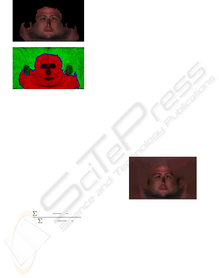
(a)
(b)
Figure 6: (a) The resulting cylindrical texture image after
cap and hair textures have been removed automatically. (b)
Color-coded triangles of the texture mesh: each red triangle
has all of its vertices bound to the input color image; blue
triangles have at lease one bound vertex and one unbound
vertex; the vertices of green triangles are all unbound.
2. Only one or two vertices of are bound to the in-
put image (blue triangles).
3. No vertex of is bound to the input image (green
triangles).
In the first case, we rasterize
˜
in texture space.
For each texel T
i
, we color it with the color of the
image pixel P
i
that corresponds to T
i
. In the second
case, we color vertices of
˜
that are bound to the in-
put image with the pixel colors of the corresponding
pixels simply as in the first case. For each unbound
vertex
˜
x
j
, we check the vertices in its one-ring neigh-
bors that are colored by being bound to the input im-
age.
˜
x
j
is then colored by summing up the weighted
colors of all the colored vertices
˜
x
i
around it.
C(
˜
x
j
)=
n
i=1
cos(
d
i
d
max
·
π
2
)C(
˜
x
i
)
n
i=1
cos(
d
i
d
max
·
π
2
)
(5)
where n is the number of colored neighboring ver-
tices, d
i
are lengthes of the edges linking between x
i
and x
j
in the original 3D generic mesh, and d
max
is
the maximal edge length in the generic mesh. The
weight term measures the normalized distance be-
tween two vertices, and favors the vertices that are
much closer to the considered vertex. With the vertex-
to-image binding information, the texels of the raster-
ization of
˜
can be grouped into two sets: T
t
and T
c
.
Textured texel set T
t
represents the set of texels that
have a corresponding pixel in the input image. We
thus color this set of texels with their corresponding
pixel colors. If a texel T
i
has no corresponding pixel,
it is categorized into the colored texel set T
c
. For each
T
i
∈ T
c
, we determine its barycentric coordinates
(α
i
,β
i
,γ
i
) w.r.t.
˜
and compute the corresponding
color C(T
i
) by interpolating the vertex colors of
˜
:
C(T
i
)=α
i
C(
˜
x
1
)+β
i
C(
˜
x
2
)+γ
i
C(
˜
x
3
) (6)
In the last case, all vertices of
˜
are unbound to
the input image and can not be colored by any of the
previously described schemes. This problem is ad-
dressed in a two-stage process: First, we iteratively
assign an interpolated color to each unbound vertex.
We then perform the color interpolation scheme for
the remaining triangles of
˜
that have not been col-
ored. The first step iteratively loops over all unbound
and uncolored vertices of the 2D texture mesh. For
each unbound vertex
˜
x, we check if the vertices in the
one-ring around
˜
x are colored (either by being bound
to the input image or by having an interpolated color).
If this is true, we assign to
˜
x the weighted sum of
colors of all the colored vertices around
˜
x using Eq.
5, otherwise we continue with the next unbound ver-
tex. We repeat this procedure until there are no fur-
ther vertex updates. After this step, the first round of
vertices connecting to the vertices in case 2 has been
colored. Next, we start the same procedure iteratively.
At each iteration we color new round of vertices ad-
jacent to the round of vertices colored in the last it-
eration. Upon termination of this loop, all vertices of
the texture mesh are either bound or colored and the
remaining triangles of
˜
can be colored using the in-
terpolation scheme from the second case.
Figure 7: Synthesized cylindrical full-head texture.
Since the input image has been acquired under un-
controlled illumination, the skin color might differ
noticeably between the left and right sides of the face.
In this case, boundary might appear at the intersec-
tion between the sagittal plane (vertical plane cutting
through the center of the face) and back of the head.
We apply a weighted average spline method (Peleg,
1981) to remove the visual boundary. Fig. 7 shows
the generated full-head texture after having synthe-
sized from the remaining face texture and applied the
weighted average spline to smoothly blend pixel col-
ors in the leftmost and rightmost texture regions.
5.3 Texturing Ears
The ears have an intricate geometry with many folds
and fail to project without overlap on a cylinder. Nev-
ertheless, it is possible to automatically and quickly
AN EFFICIENT TEXTURE GENERATION TECHNIQUE FOR HUMAN HEAD CLONING AND MORPHING
271
generate the texture from a single input image where
the ears are clearly visible.
We use a deformation technique based on feature
points to warp the reference ear model to an individ-
ual ear model for obtaining appropriate texture coor-
dinates. We use the acquired 2D image that contains
the individual ears as the target model (see Fig. 1 (b)).
We identify a small set of feature points in the input
image. In practice, we use fourteen feature points for
each ear, see Fig. 8 (a). As illustrated in Fig. 8 (b), our
generic model is tagged with the same feature points
by default. To segment ears, we predefine a bounding
box enclosing each ear for the generic mesh (see Fig.
8 (d)). Before fitting the reference ears to the target
shape, we need to transform positions of the reference
ear model into the coordinate system of the target ear
image. The segmented ears are transformed and pro-
jected onto the 2D image plane of the target ear image
(see Fig. 8 (e)). For the target feature points in the
input image, they can be easily detected due to their
distinct color and their image positions are calculated.
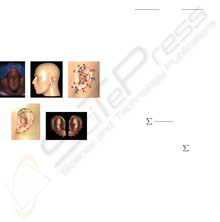
(a) (b) (c)
(d) (e)
Figure 8: (a) and (b) Position of feature points in the input
2D image and 3D generic model, respectively. (c) Ear fea-
ture points. Blue ones are used for the global alignment.
(d) Bounding box around a ear. (e) Projected reference ear
meshes with feature points.
Given two sets of N corresponding source feature
points p
i
and target feature points p
∗
i
in the image
plane, we fit the projected reference ear mesh F to
the target ear shape in the input image F
∗
in a global-
to-local fashion. Our ear fitting process consists of
global alignment and local adaptation. We use a sub-
set consisting of five features points for the global
alignment (see Fig. 8 (c)). The center of F, p
c
, is de-
fined as the midpoint between p
5
and p
m
which is the
midpoint between p
1
and p
9
. The center of F
∗
, p
∗c
,
is calculated in the same way. Let an arbitrary ver-
tex x ∈ R
2
on F move to its new position x
∈ R
2
,
S ∈ R
2×2
be the scaling matrix, R ∈ R
2×2
be the
rotation matrix, and T ∈ R
2
be the translation vector.
Eq. 7 computes the transformation:
x
= SR(x − p
c
)+T (7)
In principle, five parameters must be estimated, the
in-plane rotation angle r, two scaling factors (s
u
and
s
v
) and two translation components (t
u
and t
v
) along
the u and v texture coordinate axes. The rotation an-
gle r is estimated as the angle between vectors
−−→
p
2
p
7
and
−−→
p
∗
2
p
∗
7
. The scaling factors are estimated from the
ratio of lengths between a pair of feature points as
measured both in F and F
∗
:
s
u
=
p
∗
5
− p
∗m
p
5
− p
m
,s
v
=
p
∗
2
− p
∗
7
p
2
− p
7
(8)
The translation vector is estimated by matching the
model center of F with that of F
∗
. The same trans-
formation is applied to the source feature points p
i
to
get their new positions p
i
for further local adaptation.
Fig. 9 (a) shows the global alignment results.
Local adaptation involves non-rigid deformation of
the transformed 2D reference ear mesh F
to fit the
target ear shape. Once we have computed a set of
2D coordinates for the transformed source feature
points p
i
, we use these values to deform the remain-
ing vertices on F
. We construct a smooth interpola-
tion function that gives the displacements between the
original point positions and the new adapted positions
for every vertex on F
. Let N be the number of fea-
ture points, w
i
be the sum of weights from all feature
points contributed to a ear mesh vertex x
i
, and l
ij
be
the distance between the vertex x
i
and a feature point
p
j
. Eq. 9 computes the displacement applied to x
i
.
x
i
=
N
j=1
w
i
− l
ij
w
i
(N − 1)
p
j
e
−µl
ij
(9)
where µ is a decay factor determined by the ear size,
and p
j
is the displacement of feature point p
j
:
p
j
= p
∗
j
− p
j
,w
i
=
N
j=1
l
ij
(10)
Texture coordinates for all vertices on the reference
ear model are obtained by normalizing the newly
adapted vertex positions in the image plane to the do-
main [0, 1]
2
. Fig. 9 (b) shows the local adaptation re-
sults. In the final rendering of the head, the ear parts
are textured in a separate process with the assigned
individual texture map shown in Fig. 1 (b).
6 RESULTS
Fig. 10 shows the final texture-mapped head, where
the texture image shown in Fig. 7 is applied to the
adapted generic head model shown in Fig. 3 (a). The
scanned data in Fig. 1 has a nice shape, but dose not
have good shape and texture for back part and ears.
Through our method using deformation and texture
GRAPP 2006 - COMPUTER GRAPHICS THEORY AND APPLICATIONS
272
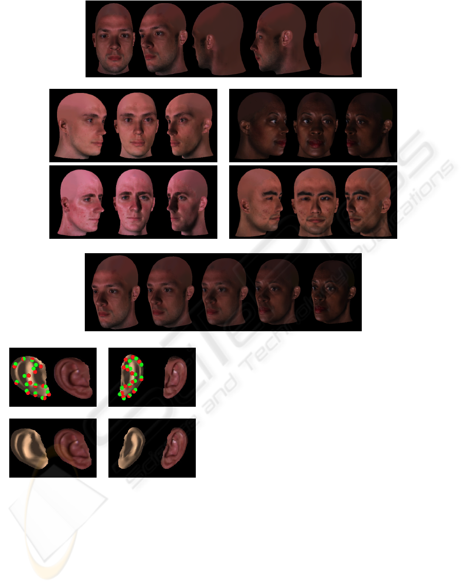
Figure 10: Different views of the head model rendered with the generated full-head texture.
Figure 11: Examples of texture-mapped heads of various people.
Figure 12: Dynamic morphing between two textured heads.
(a)
(b)
Figure 9: (a) Global alignment of the reference ear meshes
with smooth shading and texture mapping. Red and green
dots represent the transformed source feature points and de-
tected target feature points, respectively. (b) After the local
adaptation.
synthesis with a generic head, it has proper texture on
backside and ear part, which makes full rotation of a
head. We have used our method to generate full-head
textures for various individuals. Female and male in
different ethnic groups with different skin color at-
tributes are reconstructed and textured, as shown in
Fig. 11. Rendering of head models is performed in
real-time using OpenGL hardware (about 120 fps on a
2.4 GHz PC with an ATI FireGL X1 graphics board).
Our method establishes the necessary mapping be-
tween different face scans through a single, prototype
layout which enables us to morph between any two
reconstructed models. Together with the geometric
interpolation, we blend the associated textures. The
generated cylindrical full-head textures possess the
correspondence, enabling 2D texture metamorphosis.
We vary the morphing ratios to generate a dynamic
morphing between two models, as shown in Fig. 12.
In our method, the only interactive step is the ini-
tial identification of corresponding feature points on
scanned face surface for model adaptation and in ac-
quired reflectance image for texturing ears. This step
takes about 12 minutes. The automated method is
then executed to generate a full-head texture. The
RBF calculation and the morphing of the generic
mesh are performed instantaneously, taking about 2
seconds on a 2.4 GHz Pentium 4. With a dataset
of 300k points, the local deformation process runs
for about 14 seconds. Computing a parameterization
of the head mesh (approx. 5k triangles) takes about
50ms. The texture synthesis process performs 30 iter-
ations in approx. one minute, additional spline blend-
ing takes about 40 seconds. Automatic ear fitting
process runs fast, taking 0.8 seconds for fitting two
AN EFFICIENT TEXTURE GENERATION TECHNIQUE FOR HUMAN HEAD CLONING AND MORPHING
273

ears. Given the scanned data, the whole process of
creating a full-head texture takes within 15 minutes.
7 CONCLUSION
We have presented a new method to effortlessly gen-
erate a full-head texture for photorealistic head mod-
eling. We deform a generic head mesh to fit the par-
ticular face geometry using a scattered data interpola-
tion approach. We automatically parameterize the 3D
generic mesh over the 2D texture domain to establish
the mapping correspondence between different face
textures. We generate a full-head texture using color
interpolation for unbound areas and weighted average
splines for visual boundary removal. The individual
ear textures are efficiently created from a single in-
put image. Using our technique, we have been able to
generate photorealistic head models and natural look-
ing morphing with minimal manual efforts.
We would like to use an anatomy-based model de-
veloped in our previous work (Zhang et al., 2004b) as
the generic model. As it has been designed to pro-
duce real-time physically-based animation, the tex-
tured head models with the adapted anatomical struc-
ture can be animated immediately with the given mus-
cle parameters. We also plan to address the prob-
lem of non-injective mapping under the chin with
the cylindrical texture by assigning a separate texture
where that part is clearly visible to the region. Instead
of current mesh representation, independent generic
models of eyes will be used to enable rotations of the
eyeball and personal textures extracted from a photo-
graph will be applied to generic models to add indi-
vidual characteristics. Finally, automated reconstruc-
tion of hair texture from images is one of the future
challenges.
REFERENCES
Akimoto, T., Suenaga, Y., and Wallace, R. S. (1993). Auto-
matic creation of 3d facial models. In IEEE Computer
Graphics and Application. 13(5): 16-22.
Blanz, V. and Vetter, T. (1999). A morphable model for the
synthesis of 3d faces. In Proc. SIGGRAPH’99, pages
187–194.
DeCarlo, D., Metaxas, D., and Stone, M. (1998). An an-
thropometric face model using variational techniques.
In Proc. SIGGRAPH’98, pages 67–74.
Essa, I. and Basu, S. (1996). Modeling, tracking and inter-
active animation of facial expressions and head move-
ments using input from video. In Proc. Computer An-
imation’96, pages 68–79.
Guenter, B., Grimm, C., Wood, D., Malvar, H., and Pighin,
F. (1998). Making faces. In Proc. SIGGRAPH’98,
pages 55–66.
Kahler, K., Haber, J., Yamauchi, H., and Seidel, H. P.
(2002). Head shop: Generating animated head models
with anatomical structure. In Proc. ACM SIGGRAPH
Symposium on Computer Animation, pages 55–64.
Kalra, P., Mangili, A., Thalmann, N. M., and Thalmann, D.
(1992). Simulation of facial muscle actions based on
rational free form deformatios. In Proc. Proc. EURO-
GRAPHICS’92, pages 59–69.
Koch, R., Gross, M., Carls, F., Buren, D., Fankhauser, G.,
and Parish, Y. (1996). Simulating facial surgery using
finite element models. In Proc. SIGGRAPH’96, pages
421–428.
Lee, W. S. and Thalmann, N. M. (2000). Fast head model-
ing for animation. In Journal Image and Vision Com-
puting. 18(4): 355-364.
Lee, Y., Terzopoulos, D., and Waters, K. (1995). Real-
istic modeling for facial animation. In Proc. SIG-
GRAPH’95, pages 55–62.
Liu, Z., Zhang, Z., Jacobs, C., and Cohen, M. (2001). Rapid
modeling of animated faces from video. In Journal of
Visualization and Computer Animation. 12(4): 227-
240.
Marschner, S., Guenter, B., and Raghupathy, S. (2000).
Modeling and rendering for realistic facial animation.
In Proc. 11th EG Workshop on Rendering, pages 231–
242.
Nielson, G. M. (1993). Scattered data modeling. In IEEE
Computer Graphics and Application. 13(1): 60-70.
Parke, F. I. (1972). Computer Generated Animation of
Faces. Master’s thesis, University of Utah.
Parke, F. I. (1982). Parameterized models for facial anima-
tion. In IEEE Computer Graphics and Application.
2(9): 61-68.
Peleg, S. (1981). Elimination of seams from photomosaics.
In Proc. Conference on Pattern Recognition and Im-
age Processing, pages 426–429.
Pighin, F., Hecker, J., Lischinski, D., Szeliski, R., and
Salesin, D. H. (1998). Synthesizing realistic facial ex-
pressions from photographs. In Proc. SIGGRAPH’98,
pages 75–84.
Pighin, F., Szeliski, R., and Salesin, D. H. (1999). Resyn-
thesizing facial animation through 3d model-based
tracking. In Proc. ICCV’99, pages 143–150.
Platt, S. and Badler, N. (1981). Animating facial expres-
sions. In Proc. SIGGRAPH’81, pages 245–252.
Rocchini, C., Cignoni, P., Montani, C., and Scopigno, R.
(1999). Multiple textures stitching and blending on
3d objects. In Proc. 10th EG Workshop on Rendering,
pages 119–130.
Tarini, M., Yamauchi, H., Haber, J., and Seidel, H.-P.
(2002). Texturing faces. In Proc. Graphics Inter-
face’02
, pages 89–98.
GRAPP 2006 - COMPUTER GRAPHICS THEORY AND APPLICATIONS
274

Terzopoulus, D. and Waters, K. (1990). Physically-based
facial modeling, analysis and animation. In Journal of
Visualization and Computer Animation. 1: 73-80.
Thalmann, N. M., Minh, H., deAngelis, M., and Thalmann,
D. (1989). Design, transformation and animation of
human faces. In The Visual Computer. 5: 32-39.
Waters, K. (1987). A muscle model for animating
three-dimensional facial expression. In Proc. SIG-
GRAPH’87, pages 17–24.
Waters, K. and Terzopoulos, D. (1991). Modeling and an-
imating faces using scanned data. In Journal of Visu-
alization and Computer Animation. 2: 123-128.
Williams, L. (1990). Performance-driven facial animation.
In Proc. SIGGRAPH’90, pages 235–242.
Zhang, L., Snavely, N., Curless, B., and Seitz, S. M.
(2004a). Space-time faces: High resolution capture
for modeling and animation. In Proc. SIGGRAPH’04,
pages 548–558.
Zhang, Y., Prakash, E. C., and Sung, E. (2004b). A new
physical model with multi-layer architecture for facial
expression animation using dynamic adaptive mesh.
In IEEE Transactions on Visualization and Computer
Graphics. 10(3): 339-352.
AN EFFICIENT TEXTURE GENERATION TECHNIQUE FOR HUMAN HEAD CLONING AND MORPHING
275
