
A NEW METHOD FOR BUILDING LARGE-FORMAT TILED
DISPLAYS SYSTEMS
Sun Hanxu
School of Automation, Beijing University of Posts & Telecommunication
,
Xitucheng Road, Beijing,China
Song Jingzhou, Jia Qingxuan, Gao xin, Yao Fusheng, Cheng Tao
School of Mechanical Engineering & Automation, Beihang University, Beijing, China
Keywords: Multi-projection, Render synchronization, Stereo display, Geometric calibration, Color calibration.
Abstract: Large-format tiled display is a new emerging technology for constructing large scale,high-resolution,
immersive multi-projection virtual environment systems, which can present high-resolution stereo images. A
PC-cluster, five-display-channel tiled display system is built in this paper. It produces a 5120x768 stereo
image. The software infrastructure has been designed using a retained mode sort-first parallel rendering
paradigm. This paper discusses development issues including selecting on projectors and projection surface
to support passive stereo, synchronization tiled displays, geometric correction and color calibration etc.
Finally, overall display performance is given and future work is mentioned.
1 INTRODUCTION
In the past decades, large format displays provide
impressive visuals, high cost and technical expertise
are required to own, operate and maintain these
displays. This restricted their usage only to a few
large institutions and universities and limited the
application of virtual reality technology.
Recently, high-performance PC graphics cards
become available with low cost. This development
enables us to build clusters of high-performance
graphics PCs with reasonable cost. Now, building
Large-format tiled displays based on PC-cluster
become a trend (Michael, 2005. Raij, 2004. Raskar,
2003. Humphreys, 2002 ). It offers a large field of
view and resolution, and affords a strong immersion.
Wall-sized tiled displays are more supportive for
collaboration than regular monitors. Users stay
longer in such displays, move and discuss the
datasets more, and treat such displays as “murals”
that they repeatedly touch, inspect, walk around and
see from different viewpoints.
Following problems come out in designing large-
format tiled displays systems, including the design
of systems infrastructure framework, stereo display
implementation, geometric and color calibration etc.
The existed systems infrastructure framework
mainly had master-slave mode and synchronism
execution mode (Oliver, 2003). Geometric
correction methods mainly include hardware-based
correction, software-based correction and software
automation correction method. How to accomplish
geometric correction automatically and rapidly is
currently a hot researched field (Michael,
2003).With regard to color calibration, the
representative methods are Luminance Attenuation
Map (LAM) method (Aditi, 2002), the gamut-
matching method (Grant, 2003) and perceptually
seamless luminance balancing method (Aditi,
2003).The LAM method is simple but it decreases
the dynamic range of displays. The theoretical
disadvantage of the gamut-matching method lies in
the fact that there is no practical method to find the
common color gamut. The perceptually seamless
luminance balancing method uses expensive light
measuring instruments to address various
photometric issues.
342
Hanxu S., Jingzhou S., Qingxuan J., xin G., Fusheng Y. and Tao C. (2006).
A NEW METHOD FOR BUILDING LARGE-FORMAT TILED DISPLAYS SYSTEMS.
In Proceedings of the First International Conference on Computer Graphics Theory and Applications, pages 342-348
DOI: 10.5220/0001350903420348
Copyright
c
SciTePress
belonging judgement
load balancing
data adjustment
display
equipment
client node
strategy of object
distribution
tiling display
geometry data
rendering node
geometry
data
rendering node
geometry data
rendering node
geometry data
rendering node
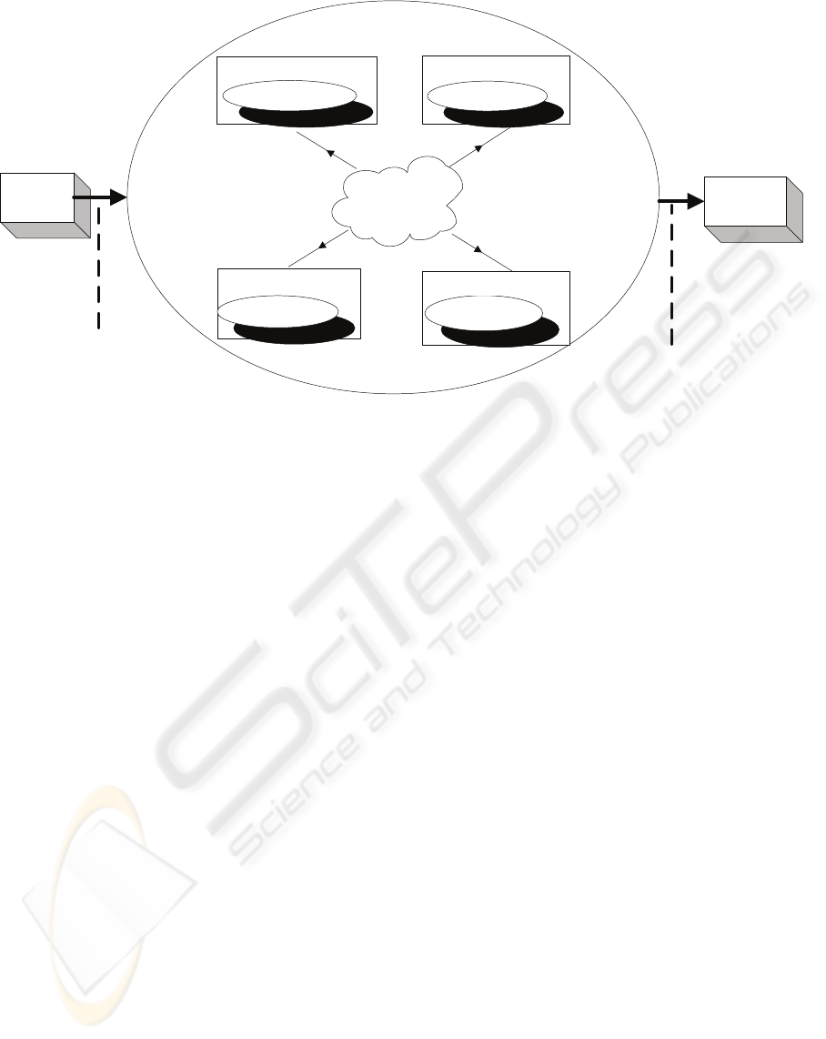
Figure1: Diagrammatic representation of the software infrastructure.
By using front-projected passive stereo displays,
commodity Personal Computers (PC), low-end
projectors, 100M Ethernet equipment, and surround
sound system, we build a low-Cost 220
0
curved
display System, which can provide interactive
graphics application for multi-projector
displays.surround sound system, we build a low-
Cost 220
0
curved display System, which can provide
interactive graphics application for multi-projector
displays.
The key problems of the presented system including
system infrastructure framework and its parallel
rendering architecture, stereo displays method,
synchronism tiled rendering control, geometry
correction, intensity blending and colour calibration,
etc. are detailedly discussed in this paper.
2 OVERALL FRAMEWORK
Unlike most display wall systems today, which use
high-end graphics workstations and high-end
projectors, our immersive curved display systems
are built with low-cost commodity components: a
cluster of PCs, PC graphic accelerator card,
consumer video and sound equipment, portable
presentation projectors and 100M common network
equipments. It relies on a PC-based distributed
rendering tiled design using a number of light
projectors operating together to form a single logical
display. The screen space is partitioned (virtually)
into a rectangular grid of tiles, each of which is
produced by one projector. The prototype system
consists of projection subsystem, graphics
generation subsystem and human-computer
interaction subsystem. Diagrammatic Representation
of the PC-Driven Curved Display system is as figure
1. The software architecture has been designed using
a retained mode (master-slave) sort-first parallel
rendering architecture (see figure 1). A copy of the
application runs on each display server. The client
handles user-interface events, and sends control
commands, including synchronization events, or
changes in view to each rendering node, i.e.
rendering server. This kind of parallel rendering
system architecture brings lower network bandwidth
load than the immediate-mode systems brings.
We have successfully developed solutions in several
research areas as outlined in this article,including
alignment of projectors, blending of overlapping
projected images, tiling output,synchronization of
displays, etc. we use front projection passive stereo
display technology to produce the virtual
environment economically , and the tiled wall
integrates a high resolution image “ tiles” into a
seamless whole better.
A NEW METHOD FOR BUILDING LARGE-FORMAT TILED DISPLAYS SYSTEMS
343
3 DESIGN AND
IMPLEMENTATION
3.1 Passive Stereo Display
One of the feature of our PC-driven display system
is that it uses front projection passive stereo display
technology to produce the virtual environment
economically. As it is known that there are two
feasible methods in implementing stereo display.
The first uses active shutter glasses synchronized
with the display refresh, which alternately block
each eye, allows successive images to be passed to
each eye in turn. The polarized glasses are
lightweight and cheap, and using passive stereo
method also avoid having to genlock all of the
render machines. The second, passive stereo,
displays two separate images at all times and uses
polarizing filters and glasses to pass the desired
images to the two eyes. To achieve the same
effective frame rate relative to a standard display,
the first method requires doubling the frame rate,
and the second method requires doubling the number
of graphics pipes and projectors. Moreover,
projectors with an extra high refresh rate are very
expensive. So we selected passive stereo instead of
active shutter glasses.
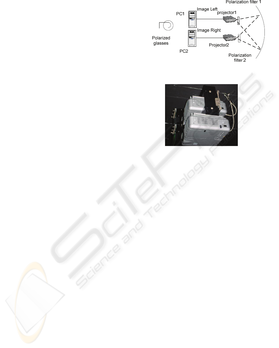
The projector display systems are divided into five
render nodes. Each render node consists of two PCs,
two projectors and polarizing filters (see figure2).
For passive stereo to work, it is important that the
two eyes receive two non-interfering images at the
same time. To achieve this, two arrays of projectors
project the image for the left and right eye
simultaneously to the screen. The light from each
projector is polarized with a polarization filter in
such a way that the image on the screen for the left
eye consists only of linearly polarized light at –45
degrees, whereas the image for the right eye is
polarized at 45 degrees. Inexpensive glasses using
the same polarization filters allow each eye to see
only light that is correctly polarized. The -45 degree
light arrives at the left eye and is blocked at the right
eye and vice versa. The dissimilarities between the
images received by the two eyes create an illusion of
dimension. This technique allows a large audience
due to the low cost of the glasses.
(a) The passive stereo display principle.
(b) the passive stereo display projectors.
Figure 2: The passive stereo display of one render node.
3.2 Synchronization Tiled Displays
The software infrastructure of our system has been
designed using a retained mode (master-slave) sort-
first parallel rendering paradigm. It runs an instance
of the program on every PC in the render clusters.
To control these programs, a client node application
runs on the console PC, which is used to transmit the
user’s inputs and viewpoint information to each
render server node. Every render server node renders
a different part of the screen from its own copy of
the scene database according the global scene view
frustum partition.
Obviously, a synchronization mechanism must be
integrated into the system for getting a logical
coherent display image. It ensures that the geometric,
viewpoint, and other graphics properties are
consistent to all of the tiles over time. It is
mandatory to fulfill two functional requirements
intrinsic to multi-projector tiled environments:
swaplock and datalock. Swaplock is the frame
buffers swaps synchronization and datalock consists
in maintaining coherent views of the scene on all the
render nodes.
Figure 3 shows the synchronization process of frame
buffer swap. The direction network message reply
methods by socket UDP communication is adopted
in our systems. When one of server nodes has
GRAPP 2006 - COMPUTER GRAPHICS THEORY AND APPLICATIONS
344
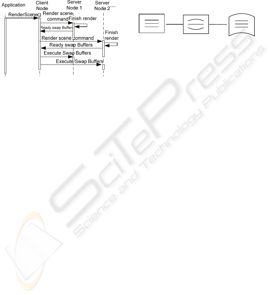
finished rendering task, it notifies client node and
ready for swap buffer. The client node controls
every process of each server node. After all server
nodes have sent their signals to the client, it is the
client node’s turn to broadcast each node to proceed
and swap buffers.
Figure 3: Synchronization process of frame buffer swap.
Data synchronization is performed implicitly
through a mechanism that keeps multiple local
replicas of a scene graph synchronized without
exposing this process to the application programmer
or user. Our own implementation of this conception
is to propagate scene graph changes using reliable
multicast. Using customer defined data structure, the
client node multicast the scene change information
to all render server node when one event arise such
as viewpoint change or mouse motion events. The
server render nodes receive the messages from the
client node and update its local scene immediately.
As a result of synchronization, the program
instances generate logical correct scene image.
3.3 Geometric Correction
Geometric correction is to address the image on
curved screen distortion in the single projection
plane and the geometric continuity of image from
adjacent projection plane. This paper applies two-
pass rendering techniques to do geometric correction.
Figure 4 shows the image distortion calibration
process of single projection plane. Let the projector
plane coordinates be denoted by (x
p
,y
p
) and the
screen space coordinates be denoted by (x
s
,y
s
). The
image calibration algorithm is as follows:
Step1. Project the regular grid pattern consisted of
sample points(x
p
,y
p
)onto the ring screen;
Step2. Compute the map: ( x
p
,y
p
)→ (x
s
,y
s
)
according to these parameters such as sreen radius,
projection center etc;
Step3. For each frame image from framebuffer,
perform the nonlinear warp by piecewise texturing
in accordance with the map in step;
Step4. The preprocessed image is sent to render
pipeline and appears on screen correctly.
Original
image
Warped
image
Correct
image
Preprocess
according to
map:(x
p
,y
p
)→(x
s
,y
s
)
Project to
curved
screen
Figure 4: Image distortion warp process.
The image align implement among multiple
projection plane is as follows:
Step1.The regular grid pattern consisted of sample
point are projected onto every channel of screen;
Step2.Adjust the position and shape of each channel
grid pattern by using our special application program,
make all channel grid pattern aligned;
Step3. Triangulate the aligned grid mesh, compute
the triangle vertex coordinates and save them as the
geometric vertex of texturing for next step;
Step4.During the render process of each channel, use
the image from each framebuffer as texture, warp
the image by piecewise texturing and then send it to
pipeline again. Lastly, get the correct aligned project
image.
Our align calibration process adopting the manual
interactively align adjustment makes a more exact
calibration result than the camera based calibration
methods.
3.4 Color Calibration
Color calibration is to blend the luminance between
the abut projection plane and keep the color
continuity of the display. The effect of intensity
blending and color correction decides the equality of
displays. For intensity blending, we adjust it using
software method with handwork interactive input.
This method attenuates the luminance of overlap
area by adjusting its alpha value. Using the special
software, the alpha value is modulated by
controlling the shape of associated NURBS curve.
Recurring to the susceptivity of human eye to
luminance, the method can achieve a preferable
blending effect and its algorithm is as follows:
Step1. Make the two abut projection plane Plane1、
Plane2 project white display simultaneously;
A NEW METHOD FOR BUILDING LARGE-FORMAT TILED DISPLAYS SYSTEMS
345
Step2. Attenuate the overlap area luminance of
Plane1 、 Plane2 by manually adjusting control
curve of alpha value until achieve a satisfied
blending effect;
Step3. Save the last results(Luminance attenuation
Map, LAM) adjusted in step 2 as the bitmap files on
PC of Plane1、Plane2;
Step4. Repeat step 1,step 2,step3 to accomplish the
intensity blending of rest of all overlap;
Step5. During the rendering process of each channel,
call its LAM and perform intensity blending
operation using mulit-texturing.
The color continuity adjustment mainly is to solve
the color difference brought by the different gamut
of projectors. The automatic software calibration
method is designed to perform the color calibration
as follows:
Step1. Input projector P1 a series of input, im with
scheduled RGB value, then feedback the response
luminance by a camera and according to it, compute
the gamma response curve of P1;
Step2. For the projector P2 which is abut with P1,
by modifying the input of P2, let the gamma
response curve approach to the one of P1 and
compute the gamma curve amend function of P2;
Step3. Repeating step 1, step 2, accomplish the rest
gamma response curve approach of all abut channel,
and get the corresponding gamma curve amend
functions of each projector;
Step4. During the rendering process of each channel,
load the gamma curve amend functions of each
projector using color look-up table function of
OpenGL. Last, the display attains color continuity
by modifying and adjusting input of each projector.
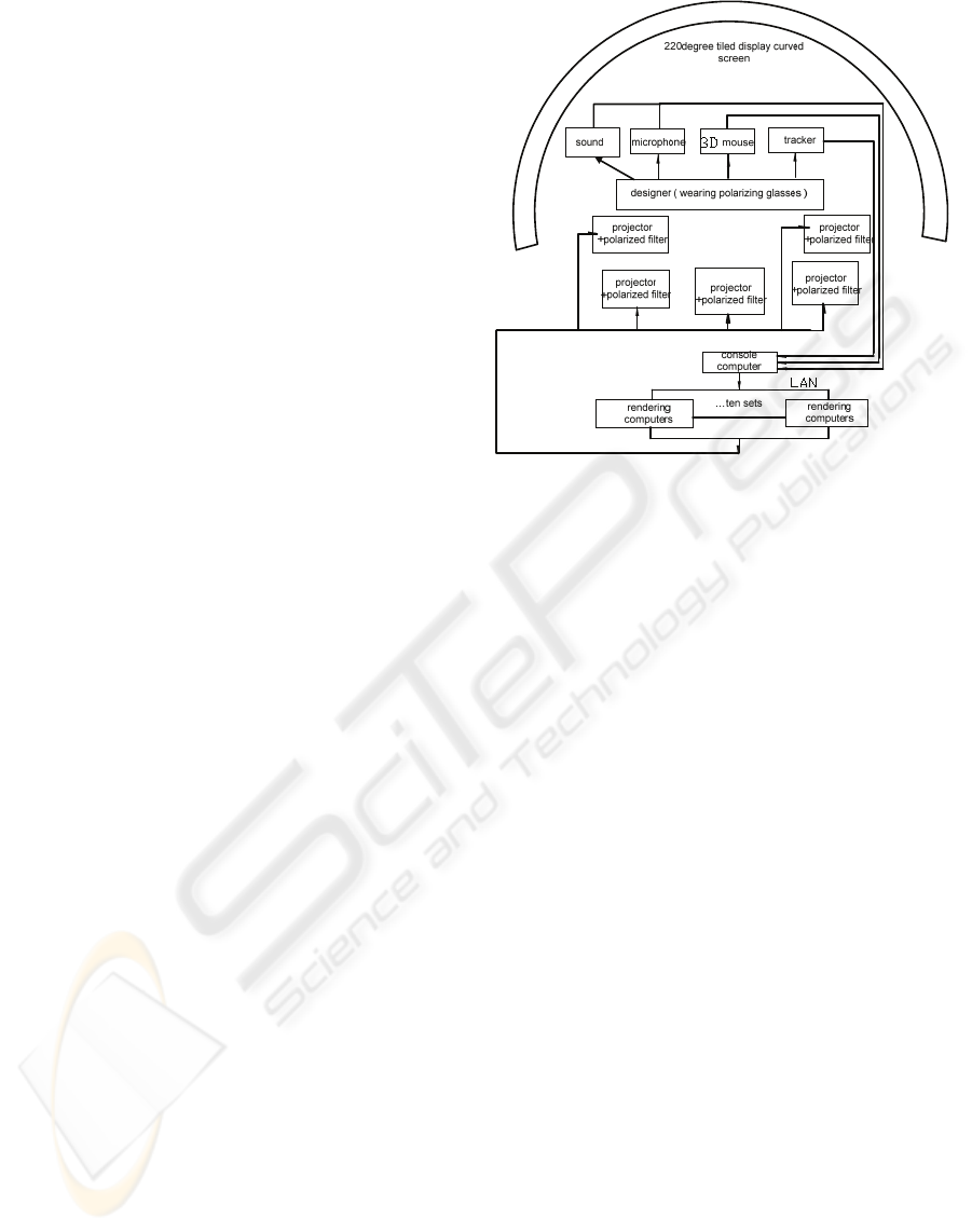
4 IMPLEMENTATION AND
RESULTS
We conducted experiments on our front-projection
ring screen display systems which have a 220 degree
view field angle. It’s hardware consists of 10 P4
2.4G PC with 512MB RAM, 10 Quadro4 750 XGL
128MB graphic cards, 100 Mbps Ethernet Switch,
10 projectors of NEC MT1065 + etc.(see figure 5).
Figure 5: The structure implement of systems.
The ring screen is 19.19 meter wide and 2.81 meter
high and has a 5 meter radius. It gives a wall
resolution of 5120 x 768 stereo image.
The system runs on Windows 2000 operation system
and its application development environment
includes such as MultiGen Creator, VC++,
OpenGL,Vtree and so on.
During the systems running, users can interact with
the virtual scene in real time and we obtain a
performance over 30 fps. The geometric continuity,
intensity blending and color continuity of the display
is satisfied and present a strong self-presence sense
as shown in Figure 6.
GRAPP 2006 - COMPUTER GRAPHICS THEORY AND APPLICATIONS
346
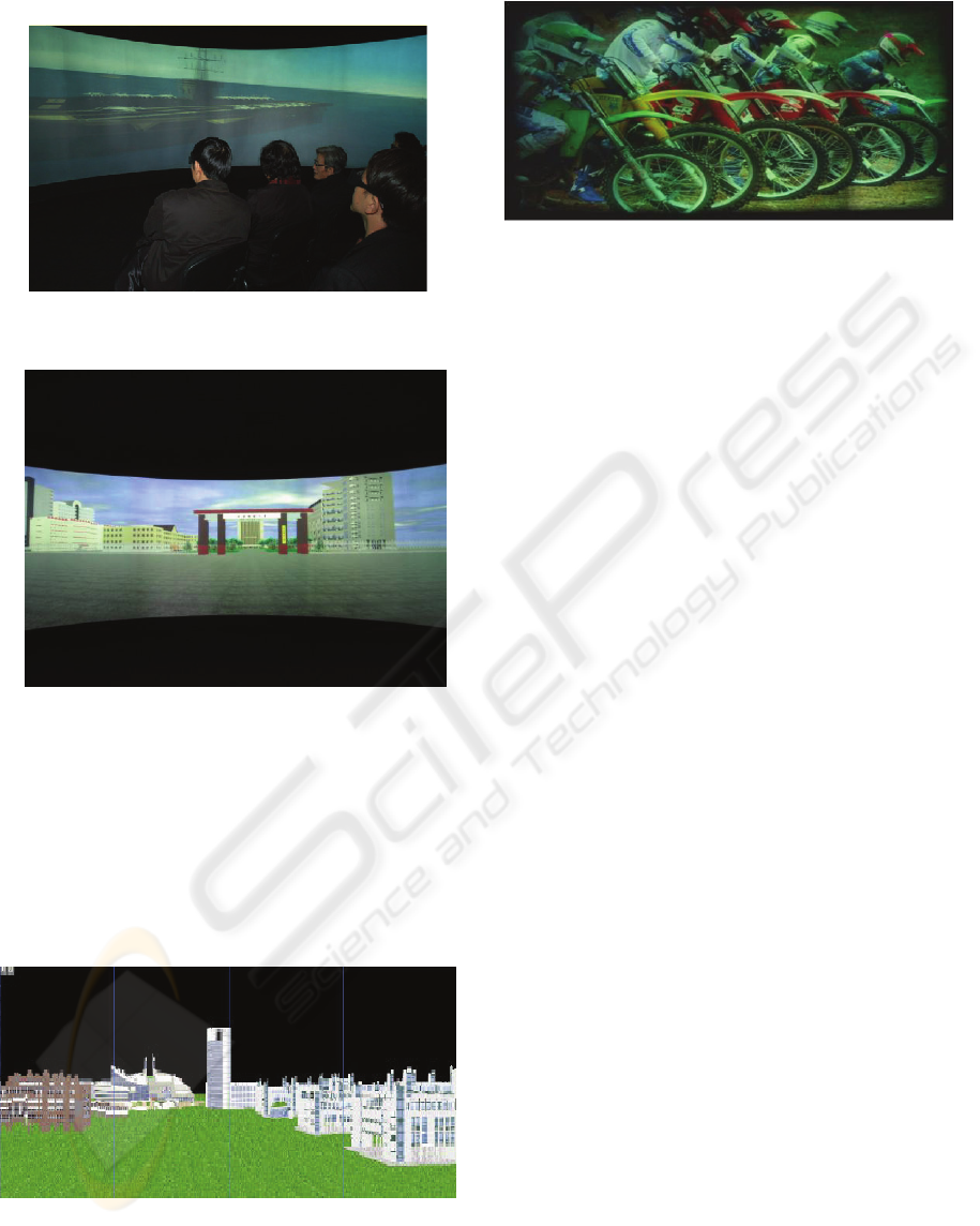
(a) the effect of a application example running.
(b) the near display effect of another example
Figure 6: Result of systems executing.
Our system adopted the human-machine interactive
software method to adjust the geometry registration
and the intensity blending, which had more exact
geometry correction precision and more consistent
intensity blending effect than the existed tiled
displays systems such as the MSPR (Zefan Jin,
2003, see figure 7, it has a “bright slot”), the system
of UNC (Aditi, 2005, see figure 8).
Figure 7: Result of MSPR systems executing.
Figure 8: The correction effect of UNC’s system.
5 CONCLUSION
The approach using a multiplicity of commodity
parts to construct a scalable display-wall system
works well, it provides a large scale , high-
resolution immersive visualization environments
capable of presenting high-resolution stereo images.
We have addressed these tradeoffs and developed
solutions in several research areas relating to screens,
projectors, synchronization tiled displays, and
integration into seamless systems.
Tiled display technologies offer a range of
opportunities for exploring scalable, high-resolution,
large-format displays, for applications ranging from
virtual manufacturing to collaboration walls to high-
resolution scientific visualization. These
technologies should increasingly become affordable
and useful in additions to the range of next -
generation displays for building active spaces.
This work suggests several areas for future research:
1. Load balancing: Load balancing algorithms are
designed to optimize the performance of parallel
systems by distributing work as evenly as possible
across each node in the system. In this paper, we
only consider scenarios in which one rendering
processor is dedicated to each display device. But,
then, if the rendering load is not uniformly
distributed over all display devices, or if we have
more graphics processors available than there are
display devices, this simple, static allocation does
not achieve optimal performance. In related work,
we will develop dynamic load balancing algorithms
for PC clusters driving a display wall. Moreover,
further work is required to develop effective load
balancing methods for remote applications.
2. Compression. In order to use this display
environment for remote computing, we need to
provide the accompanying dynamic compression
scheme, and incorporate it into the rendering
pipeline. When the source of the pixels is 2D or 3D
primitive rendering, there may be further
opportunities for efficient compression, either based
A NEW METHOD FOR BUILDING LARGE-FORMAT TILED DISPLAYS SYSTEMS
347

on compression of primitives or based on primitive-
guided pixel compression.
3. Evaluate metric. Currently we get the results from
different algorithms visually, which is subjective.
For more objective evaluation, we need a
sophisticated perceptual metric.
REFERENCES
Michael B., 2005. Camera-based calibration techniques
for seamless multiprojector displays. IEEE Transaction
on Visualization and Computer Graphics, 2005, 11(2):
193~206.
Oliver, S., 2003. A survey and performance analysis of
software platforms for interactive cluster-based multi-
screen rendering. In: Proceedings of 7th International
Workshop on Immersive Projection Technology,
Zurich, 2003.
Michael B., 2003. Advances in large-scale tiled displays.
In: Proceedings of Fourth International Conference on
Virtual Reality and Its Applications in Industry, Tianjin,
China.
Aditi M., 2002. LAM: Luminance attenuation map for
photometric uniformity in projection based displays. In:
Proceedings of ACM Virtual Reality and Software
Technology, 2002. 147~154.
Grant W., 2003. Color gamut matching for tiled display
walls. Proceedings of Immersive Projection
Technology Symposium, 2003.
Aditi M., 2003. A practical framework to achieve
perceptually seamless multi-projector displays, PhD
Thesis. North Carolina: University of North Carolina at
Chapel Hill, 2003.
Zefan, J., 2003. Study on parallel rendering system
architecture of retained mode, PhD Thesis. China
Hangzhou: Zhejiang Universtiy, 2003.
Raij A, 2004. Auto-Calibration of Multi-Projector
DisplayWalls. Proc. Int’l Conf. Pattern Recognition
(ICPR), 2004
Raskar, 2003. iLamps: Geometrically Aware and Self-
Configuring Projectors. ACM Trans. Graphics
(SIGGRAPH 2003), 2003, 22(3): 809-818
Humphreys G., 2002. WireGL: A Scalable Graphics
System for Clusters. Computer Graphics, ACM
SIGGRAPH 2001, New York: Springer Publishing
House, 2002:129-140
GRAPP 2006 - COMPUTER GRAPHICS THEORY AND APPLICATIONS
348
