
A FRAMEWORK FOR THE DEVELOPMENT OF MONITORING
SYSTEMS SOFTWARE
1
I. Mart
´
ınez-Marchena, L. Mora-L
´
opez
Dpto.Lenguajes y C.Computaci
´
on
E.T.S.I.Inform
´
atica. Univ. M
´
alaga. Campus de Teatinos. 29071 M
´
alaga, Spain
M. Sidrach de Cardona
Dpto.F
´
ısica Aplicada II
E.T.S.I.Inform
´
atica. Univ. M
´
alaga. Campus de Teatinos. 29071 M
´
alaga, Spain
Keywords:
OPC technology, monitoring systems, software engineering.
Abstract:
This paper describes a framework for the development of software for monitoring installations. Usually, the
monitoring of systems is carried out by building a programme for each installation, with no use of previously
developed programmes or, alternatively, it is carried out by using SCADA programmes (Supervisory Control
And Data Adquisition), although these tools are basically for controlling, rather than for monitoring; more-
over, taking into account the small complexity of these type of installations, the use of a SCADA program
is not justified. The proposed framework solves the monitorization of an installation in an easy way. In this
framework the generation of a monitoring programme consists of three well established steps. The first step
is to model the system or installation using a set of generic description rules and the XML language. The
second step is to describe the communications among the different devices. To do this, we have used the
OPC technology (OLE for process control). With this OPC technology, we have established an abstraction
layer that makes it possible to communicate any devices in a generic way. We have built an OPC server for
each device that does not depend on the type of device. In the third step, it is defined the way in which the
monitored data will be stored and displayed. The framework also incorporates modules that make it possible
to store and visualize all the data obtained from the different devices. We have used the proposed framework
to build complete applications for monitoring three different solar energy installations.
1 INTRODUCTION
The monitoring of systems is usually carried out by
developing a program for each installation or system,
especially if the system is not too large or complex.
The main purpose of a monitoring process is to reveal
the performance of the system, though sometimes the
monitoring process is also expected to make a long-
term evaluation of the system. However, there is no
general framework for the development of systems of
monitoring for this type of installations. As a conse-
quence, the generation of a monitoring program does
not use previously developed programmes, and usu-
ally starts from zero. Moreover, the manufacturers
of hardware are unable to make efficient drivers us-
able for different clients, chiefly because of the dif-
ferences among their client’s protocols. The tools de-
veloped in software engineering for monitoring sys-
1
This work has been partially supported by the project
ref. REN2003-05414 of the MCYT and by ISOFO-
TON,S.A. Spain.
tems have experimented a huge growth. Nevertheless,
these tools usually have no possibility of connecting
different systems and applications. It is important to
have components that make connectivity easier, (Will
et al., 2001), (Feldmann, 2001). That is, the lack
of application-level interface standards makes it dif-
ficult to interconnect the different applications. To
meet the need to distribute object-oriented function-
ality and encapsulate it with well-defined application
programming interfaces, it is developed object distri-
bution models, (Raptis et al., 2001).
We propose the use of the OPC technology (OLE
for Process Control) to solve the problem of intercon-
nection. The OPC is based on the OLE/COM tech-
nology (Objetct Linking and Embedding/ Component
Model from Microsoft), (Schellenberg, 2001), (Liu,
2005). This technology makes it possible that soft-
ware components developed by experts in one sec-
tor are used by applications in any other sector. The
design of OPC interfaces supports distributed archi-
tectures. The access to remote OPC servers is made
by using the Distributed Component Object Model
133
Martínez-Marchena I., Mora-López L. and Sidrach de Cardona M. (2006).
A FRAMEWORK FOR THE DEVELOPMENT OF MONITORING SYSTEMS SOFTWARE.
In Proceedings of the First International Conference on Software and Data Technologies, pages 133-138
DOI: 10.5220/0001320001330138
Copyright
c
SciTePress
(DCOM) technology from Microsoft, (Horstmann,
1997).
In the following sections a framework is proposed
for this purpose, and three phases for developing a
monitoring program are described. Finally, the use
of the framework for monitoring a photovoltaic solar
energy installation is presented.
2 THE FRAMEWORK
In order to develop a program for monitoring a sys-
tem, the following three steps are required: i) to
model the system; ii) to solve the communications
among the different components of the system; iii)
to define and build a method to store and recover the
historical data. Additinally, an easy way to display
the information must also be provided. Once these
problems have been solved, it is possible to obtain a
software for monitoring any installation.
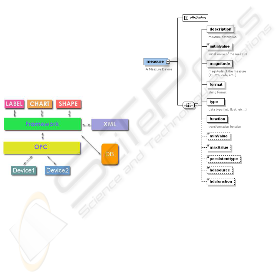
In figure 1 the general scheme of the proposed
framework and the elements that make up the system
are shown.
Figure 1: Proposed model.
3 MODELLING THE SYSTEM
The first step is to model the system or installation
using a set of generic description rules and the XML
language (XML, www) to describe the elements that
make up the system and to implement interoperation
between different object distribution models.
The descriptive powerful of XML allows us to ex-
tend the possibilities of modelling any system if more
parameters of it are to be described. In this way, we
can describe a complex system by using easy rules
that will have different characteristics and devices in
each case.
3.1 The Measure
The minimum unit usable by the system is the mea-
sure. A measure is only a representation of one chan-
nel from any device that supplies any type of infor-
mation about the system. A measure can also be one
attribute of one device (that we will treat as a constant
or calculated value). In figure 2 the scheme used for
modelling a measure is shown.
Figure 2: Modelling a measure.
As this figure shows, a measure has several at-
tributes, such as the name, a description, the associ-
ated data and the minimum or maximum value.
3.2 The Device
A device is any physical element in the installation.
Generally, the devices have some measures and at-
tributes like the name, device class and others. A de-
vice can also consist of a set of devices, each of them
with its own attributes. In figure 3 it is shown the
modelling of a device. A device will be modelled as
an element with several measures that can have at the
same time a list of elements. In this way it is possible
to model a device that consists of several devices and
ICSOFT 2006 - INTERNATIONAL CONFERENCE ON SOFTWARE AND DATA TECHNOLOGIES
134

it is even possible to create one abstract element from
a set of devices; in this abstract element its measures
could be the calculated value from any of its channels.
It is easy to build a data base of the most used de-
vices because it is possible to model a device by using
XML labels. In this way, modelling an installation
simplifies to selecting the devices that integrate the
installation and to assign values to its attributes.
Sometimes it is possible that one device consists
of several smaller devices that have to be modelled.
This can be done by grouping these devices in a set
of devices and by assigning to them the necessary at-
tributes.
3.3 The System
The system represents an installation with its devices,
its attributes and the associated channels. This is the
only information that the framework needs. From
the specifications included in the XML document, the
framework generates in runtime a structure that con-
nects to the installation and updates the measures with
the current data of the different devices. When the
framework is started the communications are begun,
and at this moment there is a one-to-one mapping be-
tween each measure attribute and the corresponding
value of the real device channel. In this way, we have
always a representation of all the device channels of
the installation.
4 THE COMMUNICATIONS
DILEMMA AND THE OPC
SOLUTION
The second step to build a monitoring program is to
describe the communications among the different de-
vices. To do this, we have used the OPC technology
(OLE for process control).
In any installation it is common to find many de-
vices of different types and manufacturers that have
different ways of communication. In order to obtain a
generic system we will have to use a general mecha-
nism to communicate with any device, irrespective of
their characteristics or the manufacturer. That is, we
must give an answer to the question of how to com-
municate with any device without modifying the sys-
tem. The OPC (OPC Foundation) technology allows
us to solve this question. With the OPC, we have es-
tablished an abstraction layer that makes it possible to
communicate any devices in a generic way. We have
built an OPC server for each device that does not de-
pend on the type of device.
The access to remote OPC servers is made by using
the Distributed Component Object Model (DCOM).
DCOM extends Microsoft’s object-oriented Compo-
nent Object Model to promote interoperation of soft-
ware objects in a distributed-heterogeneous environ-
ment, (Several, 1995), (Horstmann, 1997). A DCOM
server is a body of code that serves up particular
object types at runtime. A DCOM client calls into
a DCOM server’s exposed methods by acquiring a
pointer to one of the server object’s interface.
Once we have modelled the system we must asso-
ciate the physical channel that will supply the values
to each virtual channel. To do this, in the XML speci-
fication we add one link that indicates the OPC chan-
nel that supplies the value for the virtual channel. In
this way we connect the values of the physical devices
with our model. For example:
<measure code="MeasureCode"
ToDB="true" DBUpdateRate="0">
<function>
self.value:=
:=OPCServer.Group.OPCItem.value;
</function>
... </measure>
Sometimes it is necessary to transform a measure
from a device by using a certain function; it is possible
to do this in an easy way with the proposed scheme.
It is also possible to associate several OPC channels
with a measure of the system.
For example:
<measure code="MeasureCode"
ToDB="true" DBUpdateRate="0"> ...
<function>
self.value:=
:=OPCServer.Group.OPCItem.value+
+(OPCServer2.Group.OPCItem.value+4);
</function>
... </measure>
Hence we can build any kind of measure as a func-
tion of physical channels and numerical transforma-
tions.
A FRAMEWORK FOR THE DEVELOPMENT OF MONITORING SYSTEMS SOFTWARE
135
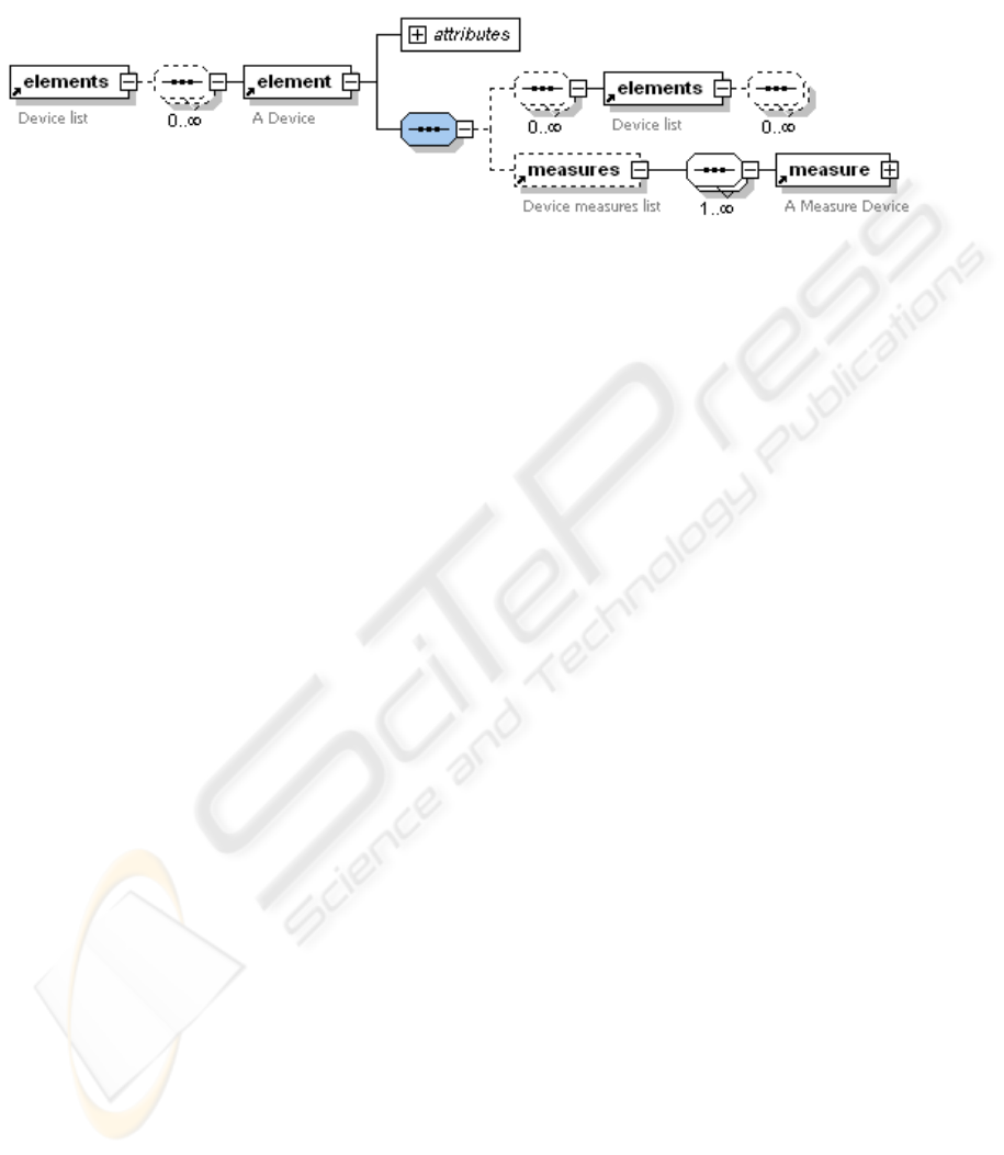
Figure 3: Modelling a device.
5 PROVIDING PERSISTENCE
In the third step of our framework, it is defined the
way in which the monitored data will be stored and
displayed.
Usually it is desirable to have a mechanism to re-
cover and store information. For this reason we will
store in a database the parameters and channels that
are being monitored. For the database we have used
the database manager Firebird (Firebird, www). Fire-
bird is a high performance and Open Source Database
system that can be deployed under several Linux en-
vironments.
By using a data base system it is possible to pro-
vide persistence to the system by just indicating in
the XML description what information must be stored
and when it must be stored.
For instance, if we want to store the temperature
value for 500 ms intervals in the data base we have
the following sentence:
<measure code="temperature"
ToDB="true" DBUpdateRate="500 ms"/>
In this way we will have in a data base all the val-
ues and states by which an installation has passed
throughout all the monitoring time.
6 THE VISUAL LIBRARY
In the previous sections it has been described how to
model a system, how to operate the different devices
and how to provide persistence to the system. How-
ever, in many cases it would be better to have a vi-
sual representation of the performance of the system
in real time.
The framework that has been developed has several
interfaces that allow us outside access using elements
that are not the inside elements of the system. For
example, it is possible to have visualization compo-
nents that can be connected to a measure whose value
is continuously shown or to graphics with information
about the historical values of a channel.
Due to the magnitude of this project and to the
large number of options, the outside access has been
modelled using design patterns, (Gamma et al., 1995).
Specifically, the Observer pattern has been intensively
used. In this way, the components only have to select
the different elements and these elements will assume
the responsibility for notifying the changes, so that the
components do the appropriate actions. In this way,
we have an easy mechanism for the visual integration
of the elements for the monitoring. This mechanism
can be easily extended to new components.
7 EXAMPLE: MONITORING A
PHOTOVOLTAIC SOLAR
ENERGY INSTALLATION.
IMPLEMENTATION AND
RESULTS
Nowadays this framework is being used for the mon-
itoring of many photovoltaic installations. In these
installations each device has several channels and in
most cases the devices belonging to different manu-
facturers, what sometimes makes it impossible to in-
tegrate the software supplied by them.
In a photovoltaic installation the following devices
are available:
1. Photovoltaic modules that collect the solar energy
2. One or more inverters that transform the direct cur-
rent collected by the modules in alternating current
3. Several additional devices or sensors that are re-
sponsible for collecting the parameters of the per-
formance of the system, such as the temperature,
the radiation, etc. In many cases the inverters have
ICSOFT 2006 - INTERNATIONAL CONFERENCE ON SOFTWARE AND DATA TECHNOLOGIES
136
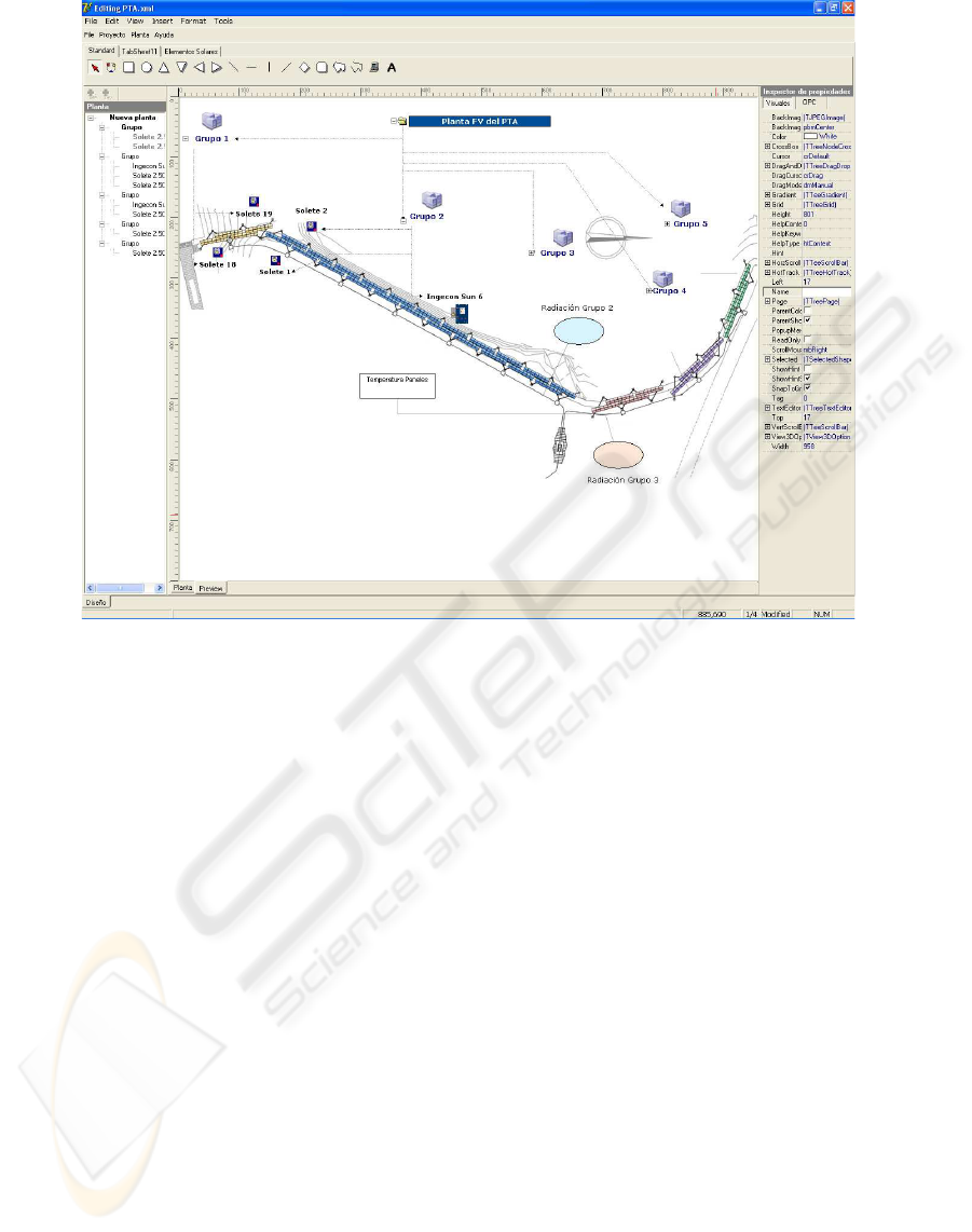
Figure 4: Modelling a photovoltaic installation.
input ports for connecting the sensors and for man-
aging their values.
Not only do the inverters have all the necessary
electronic to convert the DC in AC, but also a com-
munication port with its own protocol. This protocol
is different for different inverters.
By using a XML format file we will describe all the
element in an installation. The modelling of some of
the most used devices is already included in a XML
labels data base. Therefore, the building of the final
system is done by copying the labels of the system de-
vices and by adding them to the original XML. So, for
each inverter we will describe its attributes, its chan-
nels, the necessary virtual channel and the relation-
ship among them. Finally, we will link the different
elements with the OPC items that will be responsible
for the communications and the framework that will
be responsible for all other tasks. In figure 4 the pro-
cess of building the monitoring program is shown.
Once the installation has been modelled, we will
include in the system all the graphic elements, such
as labels, charts, shapes, and so on, and we will con-
nect the channels. In this way we have designed and
monitored this system in a fast and easy way. In figure
5 it is shown the final program when it is running.
8 CONCLUSIONS
In this paper we have described the framework that
has been developed for building monitoring programs
in an easy way. The different tools that are developed
are reusable. A library of visual functions, XML and
the proposed framework are used for generating pro-
grammes that are being used in several real installa-
tions. The framework is responsible for the commu-
nications.
In a SCADA system, both the design and the logic
of the programme are strongly joined and in most
cases the design is not very attractive. Modelling a
system using XML allows us to make an easy modifi-
cation and/or extension. Moreover, we obtain an easy
monitoring system because the framework is respon-
sible for maintaining a representation of the installa-
tion state. It is possible to get a more attractive design
because this abstraction allows us to design the visual
part by using the classical MFC, VCL or even Flash
library.
The proposed framework solves the monitoring of
an installation by reusing previously developed com-
ponents. In this framework the generation of a mon-
itoring programme is done in three phases. One of
the main contributions of the framework is the use of
XML for modelling the installation and the use of the
A FRAMEWORK FOR THE DEVELOPMENT OF MONITORING SYSTEMS SOFTWARE
137
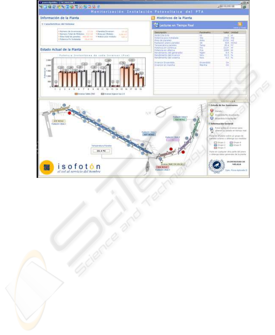
Figure 5: Result: The monitoring programme.
OPC technology for describing the communications
among the different devices.
The proposed framework has already been used for
monitoring several installations.
REFERENCES
Wills L. et al. (2001) An Open Platform for Reconfigurable
Control. IEEE Control Systems Vol.21, n.3, pp. 49-64.
Feldmann, K., Stckel, T., Gaberstumpf, B. (2001) Concep-
tion and Implementation of an Object Request Broker
for the Integration of the Process Level in Manufac-
turing Systems. J.Systems Ingetration Vol. 10, n.2,
pp.169-180.
Schellenberg, F.M., Toublan, O., Capodieci, L., Socha, B.
Adoption of OPC and the Impact on Design and Lay-
out. DAC 2001, Jun 18-22, 2001, Las Vegas, Nevada,
USA
Liu, J., Wee Lim, K. Khuen Ho, W., Chen Tan, K. Tay, A.,
Srinivasan, R. Using the OPC Standard for Real-Time
Process Monitoring and Control. IEE Software, Nov-
Dec 2005, pp. 54-59.
Gamma, E. Helm, R.J., Vlissides,J. (1995) Design patterns.
Elements of Reusable Object-Oriented Software. Ad-
dison Wesley Professional; 1st edition
Raptis, D., Spinellis,D., Katsikas,S. (2001) Multi-
Technology Distributed Objects and Their Integration.
Computer Standards and Interfaces Vol. 23, n.3, pp.
157-168.
Horstmann, M. Kirtland, M. (1997)
DCOM Architecture http :
//msdn.microsoft.com/library/def ault.asp?url =
/library/en−us/dndcom/html/msdn
d
comarch.asp
The World Wide Web Consortium (W3C) XML Specifica-
tions: http://www.w3.org/XML/
The OPC Foundation site: http://www.opcfoundation.org/
The Component Object Model Specification, Microsoft,
Oct. 1995.
Firebird home page project, http://firebird.sourceforge.net/.
ICSOFT 2006 - INTERNATIONAL CONFERENCE ON SOFTWARE AND DATA TECHNOLOGIES
138
