
A DYNAMIC ANALYSIS TOOL FOR EXTRACTING UML 2
SEQUENCE DIAGRAMS
Paolo Falcarin, Marco Torchiano
Dipartimento di Automatica e Informatica (DAUIN), Politecnico di Torino,Corso Duca degli Abruzzi 24, Torino, Italy
Keywords: UML, XMI, Dynamic Models, Aspect Orien
ted Programming (AOP), Reverse Engineering.
Abstract: There is a wide range of formats and meta-models to represent the information extracted by reverse
engineering
tools. Currently UML tools with reverse engineering capabilities are not truly interoperable due
to differences in the interchange format and cannot extract complete and integrated models. The
forthcoming UML 2.0 standard includes a complete meta-model and a well defined interchange format
(XMI). There is an available implementation of the meta-model, therefore it is a viable option to use UML
2.0 the modelling format for reverse engineered models. In this paper we propose a technique to
automatically extract sequence diagrams from Java programs, compliant to the UML 2.0 specifications. The
proposed approach takes advantage of the Eclipse platform and different plug-ins to provide an integrated
solution: it relies on a new dynamic analysis technique, based on Aspect Oriented Programming; it recovers
the interactions between objects also in presence of reflective calls and polymorphism.
1 INTRODUCTION
A significant effort in the lifecycle of software
systems is devoted to maintenance and
comprehension. Some among the currently
widespread software development practices, such as
agile software development and open source projects
devote less and less effort the production of
documentation.
Though, documentation and design models are
essen
tial for the comprehension of software.
Therefore, in order to achieve high maintainability it
is important to provide developers with automatic
tools to extract the documentation, consistent with
the actual system.
Both in academic and industrial contexts the need
fo
r usable tools to help reverse-engineering tasks is
strongly perceived. The Unified Modeling
Language (OMG) is the most used standard for
visual representation of the design of object-oriented
software. Some UML tools provide reverse-
engineering features, mainly class diagram
extraction. Few tools reverse-engineer existing
source code into a sequence diagram or
collaboration diagram (Kollmann et al. 2001). All
these tools are based on static analysis of source
code instead of dynamic analysis of the executable
files.
Static analysis has some limitations because it is
l
imited to source code. In case of polymorphism,
dynamic creation of objects, and using of reflection,
the behaviour may vary depending on data: thus,
these issues can be solved running the application,
i.e. using dynamic analysis techniques. Dynamic
extraction of objects interactions can be applied even
with a limited knowledge of the target application.
Analyzing dynamic behaviour in such cases usually
req
uires heavy code instrumentation and a reflective
language support; moreover dealing with the huge
amount of extracted information is an issue that has
to be faced with; in this case it is often necessary to
select the use case and the related parts of the system
that should be analyzed: filters should be defined to
set boundaries of the automated analysis.
Current approaches use ad-
hoc debuggers or
profilers to generate traces on files: these are then
used to generate one or more models. These
approaches differ in the kind of code instrumentation
used, in the format of extracted models, and in the
different tools and platforms they rely on: therefore
a reverse engineering task may require time on
configuration and adaptation of heterogeneous
environments.
171
Falcarin P. and Torchiano M. (2006).
A DYNAMIC ANALYSIS TOOL FOR EXTRACTING UML 2 SEQUENCE DIAGRAMS.
In Proceedings of the First International Conference on Software and Data Technologies, pages 171-176
DOI: 10.5220/0001319401710176
Copyright
c
SciTePress

In order to extract dynamic behaviour of a software
application, we present a technique based on AOP to
instrument bytecode, running test cases, and then
extracting sequence diagrams models, all integrated
in the Eclipse platform (Eclipse).
The tool we created implements several existing
techniques into a single easy-to-use plug-in. In
addition it is the first reverse engineering tool built
on top of the UML2 Eclipse plug-in.
The following sections will explain our Eclipse-
based approach, the main concepts behind AOP, and
will give more information on the UML2 Project
(UML2).
2 THE PROPOSED APPROACH
In this section we describe the approach for
extracting data from the application both statically
using reflection and at run-time using AOP. The
information extracted is used to populate the UML2
model of the system. The described approach has
been implemented by means of some wizards
working as a plug-in of the Eclipse development
environment. The tool supports the following
process to reverse engineer an application starting
from a target Java Project in Eclipse:
1. The User identifies which java packages to
inspect in the target project through a wizard in
Eclipse.
2. These packages are used as parameters for a
pre-defined template: the Eclipse Modeling
Framework (EMF) plug-in is then used for creating
an AspectTracer java file, suitable for the target
application
3. The tool changes the nature of the Java Project
in an AspectJ project: therefore a new build of the
target project will instrument the target application
with the aspect, by means of the AspectJ weaver.
4. Through another wizard, user selects a package
with the JUnit test-cases for the target application
(JUnit).
5. The wizard runs all the selected test cases and
updates the UML2 model on the fly, adding a new
interaction diagram for each test-case.
The result of the above mentioned analysis steps are
stored in an object model using the UML2 plug-in
API: this object model is based on the Eclipse
Modeling Framework and therefore it can be
serialized in a file in the standard XMI format,
compliant with the recent UML 2.0 specification.
Our approach leverage different Eclipse plug-ins to
provide, in few steps, UML 2 standard models; these
can be visualized and manipulated by whichever
UML tool able to import XMI models, without being
locked to a particular UML tool provider.
2.1 Overview of AOP
Aspect-Oriented Programming (Kiczales et al.,
1997) is a new programming paradigm easing the
modularization of crosscutting concerns in object-
oriented software development. In particular,
developers can remove scattered code related to
crosscutting concerns from classes and placing them
into elements called aspects. This methodology
relies on a join-point model, which defines the
points along the execution of a program that can be
possibly addressed by an aspect. Thus, AOP
involves a compiling process (called weaving) for
the actual insertion of aspect code into pre-existing
application source code or byte code.
AspectJ (AspectJ) is the leading AOP
implementation, and the more complete, stable and
widely used one; it includes a language
specification, a set of additions to the Java language,
a compiler that creates standard Java bytecode.
In the terminology of AspectJ an aspect is
composed by a set of pointcuts and advices. The
term ‘advice’ represents the implementation of a
crosscutting concern, i.e. additional code to be
executed in join points of the application code.
AOP also involves means for identifying the join
points to be extended by an aspect. The AOP term
‘pointcut’ implicitly defines at which points in the
dynamic execution of the program (at which join-
points) extra code should be inserted: pointcuts
describe sets of join points by specifying, for
example, the objects and methods to be considered,
or a specific method call or execution. AspectJ
offers a rich set of pointcuts: among these the ‘call’
pointcut is the more interesting for our purposes,
because it intercepts method calls: the following
simple example shows a simple call() pointcut,
which intercepts a method call, whose signature is
defined between parenthesis.
pointcut p(): call(public static
void mypackage.MyClass.main(String[]));
Thus, the former pointcut, named ‘p()’, picks up
a single join-point: the call to the public static
method ‘main’, of class ‘MyClass’ in package
‘mypackage’, with a single parameter of type
‘String[]‘ and a ‘void’ return value.
AspectJ utilizes a wildcard-based syntax to
construct the pointcuts in order to capture join points
ICSOFT 2006 - INTERNATIONAL CONFERENCE ON SOFTWARE AND DATA TECHNOLOGIES
172

that share common characteristics. Three wildcard
notations are available in AspectJ:
1. * means any number of characters except
the period.
2. .. means any number of characters
including any number of periods.
3. + means any subclass or sub-interface of a
given type.
Just like in Java, AspectJ provides a unary
negation operator (!) and two binary operators (|| and
&&) to form complex matching rules by combining
simple pointcuts. The negation operator ! allows the
matching of all join points except those specified by
the pointcut. Combining two pointcuts with the ||
operator causes the selection of join points that
match at least one of the pointcuts, while combining
them with the && operator causes the choice of join
points matching both the pointcuts.
2.2 Aspect Tracer
We defined the AspectTracer aspect to collect
information for building the sequence diagrams in
the UML2 model. In our approach a scenario is
associated with a test-case, thus a use case can be
related with a set of test-cases. Automated tests
written with JUnit act like a sort of specification of
scenarios.
Here we describe an example of AspectTracer
created for the ‘Foo’ case study.
Looking at the AspectTracer’s source code (see
Figure 1), the second line specifies the aspect name
following the AspectJ syntax. An aspect is
composed by a set of pointcuts and a set of advices.
In the aspect several pointcuts are defined and
named, in order to identify different sets of join
points in the application code; these pointcuts can
then be composed with logical operators to define
more complex pointcuts.
In order to identify these join-points, each advice
is related to one named pointcut, specifying a
particular set of join-points in the application code:
for example, whenever the related pointcut In the
aspect there are four advices of type before, used to
execute some code right before the identified join-
point, and one advice of type after, used to execute
some code right after the join-point. Each advice
contains, enclosed between braces, the additional
code that is inserted at the specified join-points
during the weaving process, at compile-time.
For example, test() matches a join-point in the
application, the advice of type before(), at line 19, is
executed immediately before the join-point.
The methodCalls() pointcut at line 9 in figure 1
can be read like this: ‘all the method calls defined in
whichever package, for whichever class, whichever
method, and whichever return value; moreover the
wildcard “..” used between method’s parenthesis,
matches whichever list of types for formal
parameters.
In the same way (see line 7) we intercept all calls
to constructor methods, identified by the keyword
‘new’.
Now we need to limit the scope to the ‘foo’
package, containing our case study to be inspected:
we define the targetPackage() pointcut to identify
all the join-points of our target application. This
pointcut relies on the AspectJ pointcut within()
which identifies all the join-points defined in the
source code of classes matching the type pattern
defined between parenthesis. For example,
“within(foo..*)” matches whichever string starting
with “foo” and followed by a string including
periods: this identifies all the join-points defined in
package “foo” and in all its sub-packages.
Wildcards are very powerful but the extensive
usage made by methodCalls() pointcut, leads to pick
up undesired join-points; thus, we need to define the
boundary() pointcut (see line 12) to describe all join-
points we want to exclude from tracing.
In particular, in order to avoid infinite recursion,
we defined the instrumentation() pointcut, which
excludes all the join points occurring inside our
instrumentation code, i.e. the AspectTracer’s body
and the related Tracer class. Moreover, we use the
init() pointcut to exclude the calls to initialization
methods, transparently inserted in bytecode during
compilation, and occurring whenever a new object is
created and its fields are initialized. Finally the
callSet() pointcut (at line 15) represents the method
calls we are interested to trace.
Whenever a method of a class in the “foo”
package is called the related ‘before()’ advice (at
line 22) is executed immediately before the join-
point: this advice simply store the caller object
reference. The keyword thisJoinPoint is, for an
aspect, what the keyword this is for Java language,
but, instead of returning the current executing object,
it returns the current join-point reached along the
execution. The getThis() method returns the
reference of the currently executing object, advised
by this aspect.
A DYNAMIC ANALYSIS TOOL FOR EXTRACTING UML 2 SEQUENCE DIAGRAMS
173

1. package it.polito.tracer;
2. aspect AspectTracerpublic {
3. pointcut targetPackage(): within(foo..*);
4. pointcut instrumentation(): within(it.polito.tracer..*);
5. pointcut init():
6. initialization(new(..)) || preinitialization(new(..)) ||
staticinitialization(*..*);
7. pointcut constructorCalls(): call(new(..)) ;
8. pointcut constructorExecutions(): execution(new(..)) ;
9. pointcut methodCalls(): call( * *..*.*(..));
10. pointcut methodExecutions(): execution( * *..*.*(..));
11. pointcut test():execution(public void test*(..))&&
within(junit.framework.TestCase+);
12. pointcut boundary(): targetPackage() && !instrumentation() && !init();
13. pointcut refMethod(): call(Object java.lang.reflect.Method.invoke(..));
14. pointcut refConstructor(): call(Object
g.reflect.Constructor.newInstance(..)); java.lan
15. pointcut callSet(): (methodCalls() || refMethod()) && boundary();
16. pointcut constructorCallSet(): (constructorCalls() || refConstructor())
ary(); && bound
17. pointcut executionSet(): (methodExecutions() || constructorExecutions())
&& boundary();
18. static Object sender; static boolean isConstructor = false;
19. before(): test() {
20. Tracer.loadModel(thisJoinPoint.getThis().getClass().getName());
21. }
22. before(): c
allSet() {
23. sender = thisJoinPoint.getThis(); isConstructor = false;
24. }
25. before(): constructorCallSet() {
26. sender = thisJoinPoint.getThis(); isConstructor = true;
27. }
28. before(): executionSet() {
29. Tracer.trace(sender,
thisJoinPoint.getThis(),thisJoinPoint.getSignature().toLongString(),
isConstructor, thisJoinPoint.getArgs());
30. }
31. after(): test() {
32. Tracer.saveModel();
33. }}
Figure 1: AspectTracer source code.
Another pointcut we used is methodExecutions()
relying on the AspectJ’s execution() pointcut, which
behaves like the call() pointcut: the only
difference is that in this case the currently executing
object (obtained with thisJoinPoint.getThis() ) is the
receiver object of a method call, instead of the caller
object.
One may question that we just need a single
before() advice for the call() pointcuts, instead of
two, to extract all the information on the sender and
the receiver objects. This is not possible because if
we write a single advice related to a call pointcut
then we are not able to extract the receiver object
reference in case of constructor method calls.
On the other hand, a single advice related to an
execution() pointcut would not be able to extract the
sender object reference. This clarifies the need to
temporarily store the sender object reference,
retrieved by the call() related advices: this value will
be used immediately after by the execution() related
advice to invoke the Tracer tool for updating the
model. At line 29, the Tracer is invoked passing
these parameters: the caller object, the receiver
object, the signature of the invoked method, and an
array of Objects containing the parameters’ values.
It is worthwhile to notice that our approach
seamlessly detects reflection-based invocations to
methods and constructors (see lines 13-14).
Therefore it allows identifying the actual target
objects in the interaction model.
Finally it is important to notice the test() pointcut
(see line 9) which intercepts the method call of a
ICSOFT 2006 - INTERNATIONAL CONFERENCE ON SOFTWARE AND DATA TECHNOLOGIES
174
whichever JUnit test-case, in order to load the
current UML2 model before starting the test, and
saving it immediately.
2.3 UML2 Sequence Diagrams
There is an ongoing effort in the Eclipse UML2
project to develop a UML2.0 compliant class library.
The object model prescribed by the OMG standard
is very complex, thus to make it usable the UML2
team introduced some simplifications.
A sequence diagram depicts a scenario by
showing the interactions among a set of objects in
temporal order. Objects are shown as vertical bars,
called “lifelines”; events or message delivery is
shown as horizontal arrows from the sender to the
receiver (see Figure 2).
A scenario describes a typical example of an
execution trace and therefore control-flow
statements and conditions are not specified.
To better understand how these classes can be
used to model a Java software system we present a
very simple example. Let’s consider two classes A
and B and we model the dynamic interaction where
obj1, instance of class A, invokes method m2() of
object obj2, instance of class B. This interaction can
be represented by a sequence diagram as shown in
Figure 2.
Figure 2: Sample Sequence Diagram.
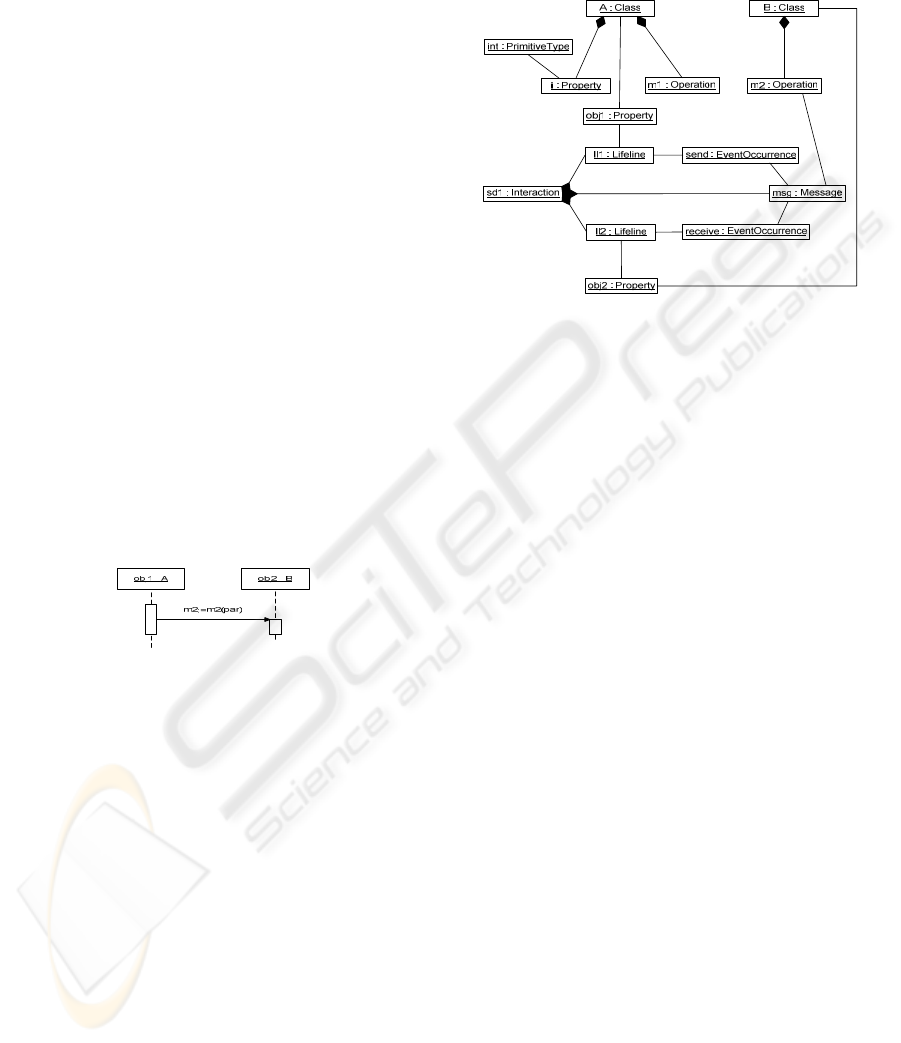
The UML2 object-model corresponding to the
sequence diagram is presented in the lower part of
Figure 3. Interaction object corresponds to a
sequence diagram and it contains the elements of the
model: lifelines and messages. The lifelines
represent instances of classes, which are represented
by class Property. The messages are linked to the
source and destination lifelines by two
EventOccurence objects: a send event and a receive
event respectively. A message represents the
invocation of a method, whose signature is
represented by class Operation.
The Interaction sd1 contains two Lifeline
objects, ll1 and ll2, which represent two objects obj1
and obj2, whose types are Class A and Class B
respectively. The Interaction sd1 contains a Message
msg that is sent by Lifeline ll1 through the
EventOccurrence send and received by Lifeline ll2
through EventOccurrence receive. The signature of
the Message msg is the Operation m2 of Class B.
Figure 3: Object-model of the sample model.
3 RELATED WORK
Recent research has shown that automated tools can
be used to help engineers understand software
systems. Commercial UML tools, and research tools
extract a UML model from a system
implementation. Typically, these tools use static
analysis to parse the system source code or bytecode
to extract a model of the system.
Shimba (Systa et al., 2001) is a reverse
engineering environment to support the
understanding of Java software systems. Shimba
integrates the Rigi (Tilley et al., 1994) and SCED
(Systa, 2001) tools to analyze and visualize the static
and dynamic aspects of a subject system. The static
software artifacts and their dependencies are
extracted from Java bytecode and viewed as directed
graph in Rigi format. The run-time information is
generated by running the target software under a
customized debugger, then the generated
information is viewed as sequence diagrams using
the SCED tool.
Jinsight (Pauw et al. 2002) is a tool for exploring
a program’s run-time behaviour, by means of an ad-
hoc graphical visualization based on execution
traces. To collect a trace, the user runs the target
program with a profiling agent and a standard JVM.
Jinsight is not able to limit the trace to invocations
of a particular method or class, and it has problems
to scale for large code-base.
A DYNAMIC ANALYSIS TOOL FOR EXTRACTING UML 2 SEQUENCE DIAGRAMS
175

We claim that AOP usage eases reverse
engineering task because code instrumentation is
modularized in a single aspect that can be easily
inserted or removed at build-time; moreover there is
no more need of customized debuggers or ad-hoc
instrumentation of source code, which are more
complex to handle and error-prone.
Thanks to the aspect-oriented platform, pointcuts
can be used to set precise tracing boundaries,
selecting which target packages or classes to inspect
and which ones to exclude.
In (Briand et al. 2005) a method to reverse
engineer UML sequence diagrams from execution
traces for distributed systems is described: they
define how transforming extracted data in a UML
1.3 model, relying on their ad-hoc meta-model to
represent sequence diagrams.
We also rely on a meta-model to generate UML
models: the innovation is that we offer an integrated
Eclipse environment relying on the UML2 project in
order to generate models compliant with the recent
UML 2 standard and exportable through XMI
standard documents.
4 CONCLUSIONS
We developed and approach to model Java programs
from dynamic points of view. The approach has
been implemented in a working Eclipse plug-in. In
summary the main highlights of the proposed
approach are:
• This is the first reverse engineering approach
and toolset using UML 2 as modelling
infrastructure.
• It works correctly also in presence of
polymorphism, allowing both a precise recovery the
correct identification of invoked methods.
• Using suitable join points it is able to recognize
invocations made through the Java reflection classes.
• It leverages the use of JUnit, the widespread
Java unit-testing framework, to trigger scenarios
executions. The test cases are formalizations or
usage scenarios. This makes the proposed approach
a suitable a-posteriori documentation tool for
processes mainly focused on code, e.g. agile and
OSS projects.
We identified several threads for further work, in
particular we plan to investigate how to determine
which tests are needed to obtain an acceptable
coverage; then compare design sequence diagrams
with the reverse-engineered ones, this will enable
checking consistency between code and models
made in an early design phase; finally we need to
validate the overall approach with large sized
software systems.
REFERENCES
AspectJ Project homepage. Retrieved July 8th, 2006, from
http://eclipse.org/aspectj
Briand, L.C., Labiche, Y., & Leduc, J, 2005. Tracing
Distributed Systems Executions Using AspectJ. In
ICSM’05, International Conference on Software
Maintenance. IEEE Press.
Eclipse Project homepage. Retrieved July 8th, 2006, from
http://eclipse.org
JUnit Project homepage. Retrieved July 8th, 2006, from
http://junit.org
Kiczales, G., Lamping, J., Mendhekar, A., Maeda, C.,
Lopes, C., Loingtier, J.M., & Irwin, J, 1997. Aspect-
oriented programming. In ECOOP’97, 11th European
Conference on Object-Oriented Programming.
Springer-Verlag.
Kollmann, R., Gogolla, M., 2001. Capturing Dynamic
Program Behavior with UML Collaboration Diagrams.
In CSMR’01, European Conference on Software
Maintenance and Reengineering. IEEE Press.
OMG, Unified Modeling Language Specification.
Retrieved at http://www.uml.org/
Pauw, W.D., Jensen, E., Mitchell, N., Sevitsky, G., &
Vlissides, J., 2002. Visualizing the Execution of Java
Programs. In Software Visualization. Springer-Verlag.
Systa, T., Koskimies, K., & Müller, H., 2001. Shimba - An
Environment for Reverse Engineering Java Software
Systems. In Software - Practice and Experience, vol.
31: 371-394. Wiley 2001.
Systa, T., 2001. On the relationships between static and
dynamic models in reverse engineering Java software.
In WCRE’99, Sixth Working Conference on Reverse
Engineering, pp. 304-313. IEEE Press.
Tilley, S. R., Wong, K., Storey, M. A. D., & Müller, H.
A., 1994. Programmable reverse engineering. In
Journal of Software Engineering and Knowledge
Engineering.
UML2 Project homepage. Retrieved July 8, 2006, from
http://eclipse.org/uml2
ICSOFT 2006 - INTERNATIONAL CONFERENCE ON SOFTWARE AND DATA TECHNOLOGIES
176
