
A UNIFIED APPROACH FOR SOFTWARE PROCESS
REPRESENTATION AND ANALYSIS
Vassilis C. Gerogiannis
Project Management Dept., T.E.I. of Larissa,Larissa, Greece,
George Kakarontzas
Information Technology and Telecom. Dept., T.E.I. of Larissa, Larissa, Greece,
Ioannis Stamelos
Department of Informatics, Aristotle University of Thessaloniki, Thessaloniki, Greece,
Keywords:
Object-Oriented Modelling, Software Process Modelling, Petri nets.
Abstract:
This paper presents a unified approach for software process management which combines object-oriented
(OO) structures with formal models based on (high-level timed) Petri nets. This pairing may be proved bene-
ficial not only for the integrated representation of software development processes, human resources and work
products, but also in analysing properties and detecting errors of a software process specification, before the
process is put to actual use. The use of OO models provides the advantages of graphical abstraction, high-
level of understanding and manageable representation of software process classes and instances. Resulted OO
models are mechanically transformed into a high-level timed Petri net representation to derive a model for
formally proving process properties as well as applying managerial analysis. We demonstrate the applicability
of our approach by addressing a simple software process modelling example problem used in the literature to
exercise various software process modelling notations.
1 INTRODUCTION
According to a recent study the software industry in
US spends approximately 275 billion dollars every
year in software development projects (Wallace and
Keil, 2004). A major part of these projects (above
70 percent) are facing problems, since they exceed
the initial cost/time estimates or, in the worst case,
they fail by not providing those deliverables and ser-
vices which have initially been proposed. There has
been a great deal of concern in software process en-
gineering community on developing satisfactory soft-
ware within timing and resource constraints (Murch,
2001).
It is the task of a software process management ap-
proach to specify and represent what must be per-
formed during each phase of a software develop-
ment project (e.g., requirements definition, specifica-
tion, design, implementation, testing etc.). The main
objective of software process management is to en-
sure that all project deliverables are provided before
project deadlines, all resulted software products sat-
isfy end-user requirements and development costs are
within the estimated budget (Murch, 2001; Royce,
1998).
Classical project modelling and planning tech-
niques (network-based techniques such as PERT and
CPM) have been found inadequate to describe all arte-
facts of a complex software process (Mehrez et al.,
1995). Various techniques have been concentrating
on relieving software project participants of difficul-
ties in understanding the activities performed dur-
ing software development. Software process mod-
elling approaches try to clarify the concurrent, iter-
ative and evolutionary characteristics embedded in
software projects, by using either formal or informal
modelling notations (Armenise et al., 1992). Formal
modelling techniques, such as Petri net-based models
(Gerogiannis et al., 1998; Murata, 1989), offer the ad-
vantages of simulation, decision making and power-
ful managerial analysis. As far as process modelling
is concerned, formal techniques provide facilities to
analyze the dynamic aspects of a software develop-
ment process by examining, for example, the dura-
tion of each project activity and sources of possible
resource conflicts (Min et al., 2000). Informal mod-
elling notations, such as the Unified Modelling Lan-
guage (UML) for object-oriented modelling (Cantor,
1998; Fowler, 2004), can be useful to represent not
only the software system under development but also
the processes performed within a project to develop a
software system.
127
C. Gerogiannis V., Kakarontzas G. and Stamelos I. (2006).
A UNIFIED APPROACH FOR SOFTWARE PROCESS REPRESENTATION AND ANALYSIS.
In Proceedings of the First International Conference on Software and Data Technologies, pages 127-132
DOI: 10.5220/0001317201270132
Copyright
c
SciTePress

Recently, various object-oriented approaches in
software process engineering domain have been uni-
fied in the so called Software Process Engineering
Metamodel (for short SPEM) (OMG, 2005). SPEM
is an adopted standard from the Object Management
Group. It utilizes UML diagrammatic notations and
provides means to describe, in abstract terms, any
software development process and its components.
Syntactic richness, user friendliness, simplicity and
flexibility of SPEM notations, make them a promis-
ing tool for software project managers, usually not fa-
miliar with formal methods. SPEM adoption can be
particularly useful to support the definition of those
processes (e.g., the Rational Unified Process (Jacob-
son et al., 1999)) which involve or mandate the use of
UML during the software development.
In this paper, instead of introducing a new model
to represent and analyze software development pro-
cesses, we propose the unification of UML models
with Petri nets. The proposed approach is centered
upon handling the inherent complexity and satisfying
various requirements met in software development
projects. The presented approach is currently under
development in the context of the MISSION-SPM
project (short for Model based Integrated Environ-
ment to Support Simulation in Software Project Man-
agement). MISSION-SPM is an R&D project that
receives funding and support from the European So-
cial Fund and the Greek Ministry of Education (in the
context of the ARCHIMEDES national research pro-
gramme). The main objective of the project is the def-
inition of a unified architecture to support the graphi-
cal representation of software development processes
and the process managerial analysis as well.
The next section of the paper presents the back-
ground of the MISSION-SPM approach. Then, in
section 3, an experimental study is presented, mod-
elling a part of a software process example with the
use of UML diagrams. In section 4, a discussion is
provided on the translation of UML process diagrams
to a corresponding formal model, expressed in a high-
level timed Petri net notation. Managerial analysis is-
sues are briefly discussed in section 5. The paper
concludes with ideas for possible directions for fur-
ther research.
2 BACKGROUND
The MISSION-SPM project focuses on exploiting the
benefits of unified approaches for software process
representation, analysis and simulation. Our research
stem from two complementary perspectives for pro-
cess representation: (1) UML based process represen-
tation, and (2) Petri net based modelling and analysis,
respectively.
The complementary diagrammatic notations of
UML can be used to represent different views of a
complex software process. For example, UML use
case or class diagrams can be used to represent the
functionality and the static structure of a software pro-
cess. These models provide appropriate constructs to
define software processes and relevant artefacts, as
well as various process performers involved in pro-
cess activities. Other notations, such as UML se-
quential diagrams, state diagrams and collaboration
diagrams, offer the means to represent the dynamic
behaviour of process elements (i.e., the operational
behaviour of process classes). These diagrams sup-
port the process planning, since they can define the
process control flow (i.e., relationships among activi-
ties and artefacts). In MISSION-SPM, usage of UML
notations is mandated by SPEM terminology for de-
scribing software processes (OMG, 2005). Roughly
speaking, a software process is divided into phases.
Phases contain activities that are performed by per-
formers (e.g., architects, programmers etc.). Each ac-
tivity has some input and produces some output. Fol-
lowing the SPEM terminology, inputs and outputs to
and from activities are called work products.
Formal models can be utilized to gain the formality
required to strongly support simulation and manage-
rial analysis. For example, Petri nets are an interesting
graphical model and they have been widely applied in
various application areas (Murata, 1989). Their math-
ematical foundation, developed over the years, has
made Petri nets a powerful, well-understood model,
especially applicable to software process modelling
(Liu and Horowitz, 1989; Chang and Christensen,
1999; Min et al., 2000). In MISSION-SPM, we have
selected the formal modelling notation of Petri nets
for the analysis of process models. Abstract process
models, initially expressed by UML diagrams, are
transformed into high-level timed Petri nets (Ghezzi
et al., 1991) for the formalisation and analysis of their
static/dynamic properties. As far as managerial anal-
ysis is concerned, simulation and rigorous analysis
techniques from the Petri net analysis domain can be
applied to examine some useful metrics and proper-
ties, such as the cumulative time consumption and the
degree of concurrency of process activities at any pro-
cess phase, the level of utilization of each process per-
former etc.
3 UML MODELS OF A PROCESS
EXAMPLE
In this section, the MISSION-SPM approach is illus-
trated by using UML class and state diagrams. We use
the class diagram presented in Figure 1 to describe
the structure of a simple software process example.
ICSOFT 2006 - INTERNATIONAL CONFERENCE ON SOFTWARE AND DATA TECHNOLOGIES
128
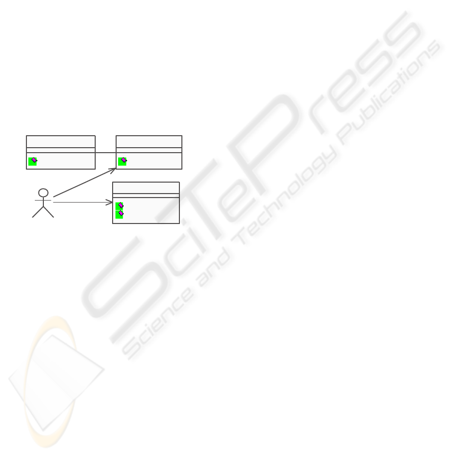
The elements of this example constitute a subset of
corresponding components met in ISPW-6 process
core problem (Kellner et al., 1991), a general soft-
ware process modelling problem used to study vari-
ous software process modelling notations. The exam-
ple refers to the design modification/review activity
of a hypothetical software development project which
involves four performers (one Design Engineer, one
Quality Assurance Engineer and two Software Engi-
neers) and one work product (the Software Design
Document). The first project task, called “Modify
Design”, is carried out by the assigned Design En-
gineer. The subsequent task, called “Review Design”,
is performed jointly by a team including the Design
Engineer, the Quality Assurance Engineer and the
two Software Engineers. The class diagram in Fig-
ure 1 presents some of the main methods of these pro-
cess elements (depicted as classes) and the possible
associations among them. For the sake of simplic-
ity, class attributes and stereotype names are not pre-
sented in the class diagram. The operational seman-
SWEngineer
ChangeDesign()
SWDesignDoc
ModifyDesign()
ReviewDesign()
DesignEngineer
QAEngineer
ReviewDesign()
22
Figure 1: Class Diagram for the Example Process.
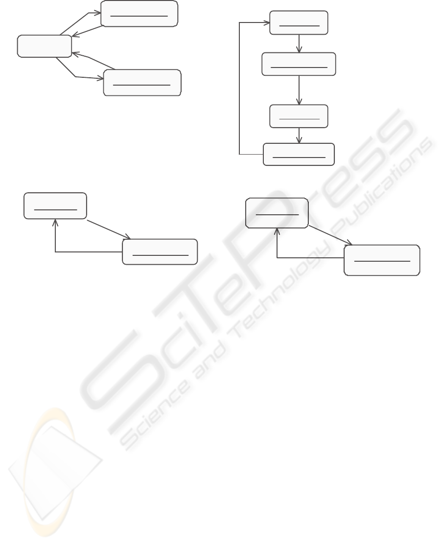
tics of the process elements involved in this example
can be captured by using four state diagrams, one for
each process element respectively (Figure 2). State
diagrams describe the states and state transitions of
the process elements (classes) and interact through in-
vocation of services. Services represent certain man-
agement decisions/responsibilities, as well as corre-
sponding communication messages (notifications for
start/completion of activities). Therefore, events and
actions correspond to requests for services (e.g., exe-
cution of performers’ activities), completions of ser-
vices and acknowledgments of service completions.
4 TRANSFORMING UML
MODELS INTO PETRI NETS
Various approaches have been proposed for the for-
malisation of UML diagrams with Petri net models in
different application domains. For example, state di-
agrams and collaboration diagrams have been trans-
lated into stochastic Petri nets to apply performance
analysis (Pooley and King, 1999). Activity diagrams
have been augmented with the operational semantics
of Coloured Petri nets (Jensen, 1995) to represent
complex workflow structures (Eshuis and Wieringa,
2001). Class diagrams have been formalised with
object-oriented Petri nets (Delatour and Paludetto,
1998) to analyse the timing behaviour of real-time
systems. In other approaches, class and state di-
agrams have been transformed into high-level Petri
nets (Baresi and Pezze, 2001b; Baresi and Pezze,
2001a) to reason on the dynamic aspects of software
systems by applying simulation and reachability anal-
ysis.
In general, all these translation schemes from UML
diagrams into Petri nets follow two alternative ap-
proaches. According to the first alternative, states of
activities are mapped into Petri net places. The sec-
ond option is to associate states with Petri net transi-
tions. In MISSION-SPM, we have followed the first
approach, since it is more natural, according to the
original Petri net semantics (Murata, 1989), to asso-
ciate states and activities with Petri net passive com-
ponents (places) and spontaneous actions, denoting
start/end of activities, with Petri net active compo-
nents (transitions).
The adopted approach is based on the transfor-
mation rules presented in (Baresi and Pezze, 2001b;
Baresi and Pezze, 2001a) which aim to automate the
production of a high-level Petri net by taking as input
UML class and state diagrams. The advantage of this
selection is the generation of a highly expressive for-
mal notation augmented with data structures for mod-
elling net tokens, as well as with predicates, actions
and timing parameters for describing net transitions.
We attempt to further exploit the adopted approach
by introducing relevant semantics from the software
process management domain. Tokens play the role of
the artefacts of a certain software process. Thus, a
high-level timed Petri net model is automatically pro-
duced to provide a highly condensed representation of
a software process.
More specifically, based on the transformation al-
gorithm described in (Baresi and Pezze, 2001a), each
process class, already defined in a UML class dia-
gram, is represented by a high-level timed Petri sub-
net, in which there are two places for each identified
service, one representing the service request and an-
other indicating the service completion. This way, we
can describe various kinds of conceivable interactions
between the process elements, including methods’
invocations, either parallel or sequential, requiring
acknowledgment or not (i.e., synchronous or asyn-
chronous interactions). States for each process class,
already specified in a UML state diagram, are trans-
lated into net places in the corresponding Petri net;
state exit actions are transformed into net transitions,
A UNIFIED APPROACH FOR SOFTWARE PROCESS REPRESENTATION AND ANALYSIS
129
Available
ModifyingDesign
exit/ Release
ReviewingDesign
exit/ Release
[ modify design completed ]
[ review design completed ]
Assign
^SWDesignDoc.ModifyDesign
Assign
^SWDesignDoc.ReviewDesign
Current
exit/ GetDoc
UnderModification
exit/ ReleaseDoc
Modified
exit/ GetDoc
[ modification completed ] /
modify design completed = TRUE
ModifyDesign
UnderReview
exit/ ReleaseDoc
ReviewDesign
[ review completed ] /
review design
completed = TRUE
(a) Design Engineer
(b) Software Design Document
Available
exit/ Assign
ReviewingDesign
exit/ Release
ReviewDesign
^SWEngineer.ChangeDesign
[ change completed ]
(c) Quality Assurance Engineer
Available
Changing Design
exit/ Release
exit/ Assign
Change Design
[change completed] /
Change completed = TRUE
(d) Software Engineer
Figure 2: State Diagrams for the Elements of the Example Process.
while state transitions are translated into arcs between
corresponding places and transitions in the resulted
Petri net. Instances of process performers and work
products (i.e., the individual objects of each process
class) are modelled with (typed) tokens accumulated
in the corresponding places.
Considering the ISPW process example, we use
one token to represent the Design Engineer, one for
the Quality Assurance Engineer, one for the SW De-
sign Document and two tokens representing the two
Software Engineers. The resulted subnets can be
merged together in one final net by fusing places.
Places are merged together when there is a pair of
places for the same service, one asking for the service
and the other offering it. The application of this trans-
formation method to the example process results in
the high-level timed Petri net of Figure 3, where type
definitions of tokens as well as transitions’ predicates,
actions and enabling intervals (Ghezzi et al., 1991) are
not listed, for the sake of simplicity. For example, the
enabling predicate of transition SWEngineer.Assign
requires both tokens in SWEngineer.Available place
to be active. By applying this transformation proce-
dure, the final net has the structure of a marked graph
(Murata, 1989) (i.e., each place has exactly one input
transition and exactly one output transition), thus it
allows the specification of synchronisation structures.
The final net is composed of four subnets, which cor-
respond to the original elements of the process ex-
ample, respectively (i.e., the Design Engineer subnet,
the SW Design Document subnet, the Quality Assur-
ance Engineer subnet and the Software Engineer sub-
net). The Design Engineer subnet invokes the modify
design method of the SW design document subnet.
After the acknowledgment receipt (i.e., the notifica-
tion that design modification is completed), the De-
sign Engineer subnet performs a parallel method in-
vocation to the SW design document and the QA En-
gineer subnet, requiring from them the design review.
The QA Engineer subnet, in turn, requires from both
SW Engineers to perform possible design changes.
ICSOFT 2006 - INTERNATIONAL CONFERENCE ON SOFTWARE AND DATA TECHNOLOGIES
130
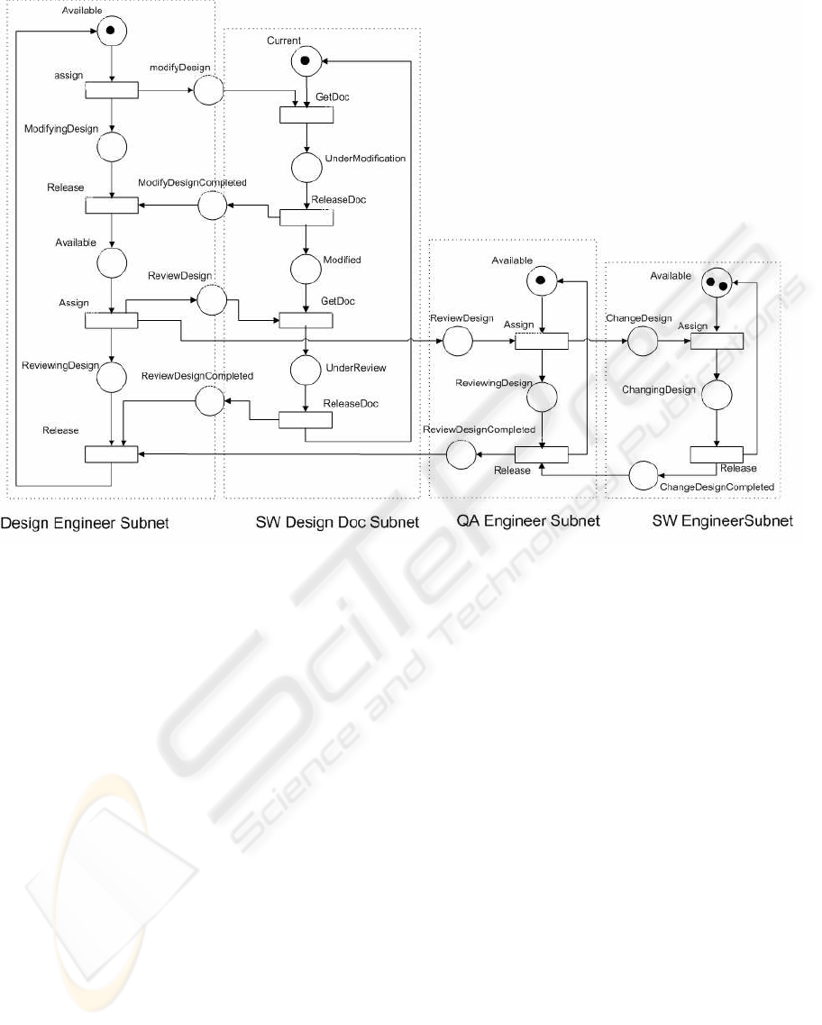
Figure 3: High-level Timed Petri Net for the Example Process.
5 MANAGERIAL ANALYSIS
ISSUES
The resulted formal representation of process ele-
ments can be analysed and verified by various Petri
net based analysis techniques, such as simulation,
reachability analysis, model checking and verification
of structural net properties (Murata, 1989). Analysis
on the resulted marked graph structure may be par-
ticularly helpful to detect possible structural failures,
such as deadlocks of the whole process. As far as
analysis of dynamic properties is concerned, we can
assign timing information to the resulted Petri net by
associating timestamps with tokens and enabling time
intervals with transitions. Then, simulation to the re-
sulted high-level timed Petri net can be conducted to
examine some important decision making elements,
such as the cumulative time consumption and the de-
gree of concurrency of process activities, at any pro-
cess phase, the level of utilization for each process
performer etc. Moreover, the use of automated tools,
such as CPN tools (Jensen, 1995), can facilitate the
process of modelling and analysis.
The simplest analysis technique is to apply simula-
tion (i.e., execute all transition firings) on the net of
Figure 3, in order to discover possible delays in the
software modification and review process. For exam-
ple, when the timestamps of the two tokens in place
SWEngineer.Available have different values, the one
with the greater timestamp (say SW Engineer 2) will
delay the other (say SW Engineer 1). This situation
can be solved by further decomposing the SW Engi-
neer subnet in two other subnets, representing explic-
itly the two SW Engineers. Then, the QA Engineer
can request, in sequence, from the two SW Engineers
to perform possible design changes.
6 CONCLUSIONS
In this paper, we have briefly discussed the unification
of object-oriented structures of software development
processes with (high-level timed) Petri nets. This
“pairing” may be proved beneficial not only for the
integrated modelling of software development pro-
cesses, involved performers and work products, but
also in analysing properties and detecting errors of
a software process specification, before the process
A UNIFIED APPROACH FOR SOFTWARE PROCESS REPRESENTATION AND ANALYSIS
131

specification is put to actual use. UML based dia-
grammatic representations of processes facilitate soft-
ware project managers/engineers in understanding the
elements of a software process model, while the di-
rect executability of the resulted Petri nets provides
the means for simulation support. We have demon-
strated the applicability of our approach by describ-
ing a part of a standard software process modeling
example problem with UML diagrams. The subse-
quent analysis can be performed on a mechanically
generated Petri net representation.
The further development of our approach is an
ongoing task that takes place within the context of
MISSION-SPM project. Our current efforts concen-
trate on:
• exploitation of existing techniques to transform
other dynamic UML models of software processes
(e.g., activity diagrams) to equivalent formal repre-
sentations, expressed in terms of high-level timed
Petri nets (Eshuis and Wieringa, 2001),
• experimentation of various types of analysis tech-
niques on the resulted nets, in order to assist the
managerial decision process (Min et al., 2000), and
• specification of a fully compliant implementation
of our approach with the modelling constructs of
the SPEM metamodel; such a compliance will
make the MISSION-SPM approach general enough
to express and analyse various scenarios met in a
range of software development processes.
REFERENCES
Armenise, P., Bandinelli, S., Ghezzi, C., and Morzenti, A.
(1992). Software Process Representation Languages:
Survey and Assessment. In 4th International Confer-
ence on Software Engineering and Knowledge Engi-
neering, pages 455–462.
Baresi, L. and Pezze, M. (2001a). Improving UML with
Petri Nets. Electronic Notes in Theoretical Computer
Science, 44(4):1–13.
Baresi, L. and Pezze, M. (2001b). On Formalizing UML
with High-Level Petri Nets. Concurrent Object-
Oriented Programming and Petri Nets, Advances in
Petri Nets, LNCS 2001:276–304.
Cantor, M. (1998). Object - Oriented Project Management
with UML. John Wiley & Sons.
Chang, C. and Christensen, M. (1999). Net Practice
for Software Project Management. IEEE Software,
16(6):80–88.
Delatour, J. and Paludetto, M. (1998). UML/PNO: A Way
to Merge UML and Petri Net Objects for the Analysis
of Real-Time Systems. In OO Technology and Real
Time Systems Workshop (ECOOP’ 98), volume LNCS
1543, pages 511–514.
Eshuis, R. and Wieringa, R. (2001). A Real-Time Execu-
tion Semantics for UML Activity Diagrams. In Proc.
of Fundamental Approaches to Software Engineering
(FASE 2001), volume LNCS 2029, pages 76–90.
Fowler, M. (2004). UML Distilled. Addison-Wesley.
Gerogiannis, V. C., Kameas, A., and Pintelas, P. (1998).
Classification & Comparative Study of High-Level
Petri Nets. Journal of Systems & Software, 43(2):133–
160.
Ghezzi, C., Mandriolli, D., Morasca, S., and Pezze, M.
(1991). A Unified High-Level Petri Net Formalism for
Time-Critical Systems. IEEE Transactions on Soft-
ware Engineering, 17:160–172.
Jacobson, I., Booch, G., and Rumbaugh, J. (1999). The Uni-
fied Software Development Process. Addison-Wesley.
Jensen, K. (1995). Coloured Petri Nets: Basic Concepts,
Analysis Methods and Practical Use, volume 1 & 2.
Springer.
Kellner, M., Feiler, P. H., Finkelstein, A., Katayama, T.,
Osterweil, L. J., Penedo, M. H., and Rombach, H. D.
(1991). ISPW-6 Software Process Example. In CS, I.,
editor, 1st International Conference on the Software
Process, pages 176–187.
Liu, L. C. and Horowitz, E. (1989). A Formal Model for
Software Project Management. IEEE Transactions on
Software Engineering, 15(10):280–293.
Mehrez, A., Muzumdar, M., Acar, W., and Weinroth, G.
(1995). A Petri-Net Model View of Decision Making:
An Operational Management Analysis. Omega Inter-
national Journal in Management Science, 23(1):63–
78.
Min, S. Y., Lee, D. H., and Bae, D. H. (2000). SoftPM:
A SW Process Management System Reconciling For-
malism with Easiness. Information & Software Tech-
nology, 42(1):1–16.
Murata, T. (1989). Petri Nets: Properties, Analysis and Ap-
plications. Proceedings of the IEEE, 77(4):541–580.
Murch, R. (2001). PM Best Practices for IT Professionals.
Prenctice Hall.
OMG (2005). Software Process Engineering Metamodel,
Ver. 1.1. OMG.
Pooley, R. and King, P. (1999). Using UML to Derive
Stochastic Petri Net Models. In 15th Annual UK Per-
formance Engineering Workshop, pages 45–56.
Royce, W. (1998). Software Project Management: A Uni-
fied Framework. Addison-Wesley.
Wallace, L. and Keil, M. (2004). Software Project Risks
& Their Effect on Outcomes. Communications of the
ACM, 47(4):68–73.
ICSOFT 2006 - INTERNATIONAL CONFERENCE ON SOFTWARE AND DATA TECHNOLOGIES
132
