
MODELLING THE UNEXPECTED BEHAVIOURS OF
EMBEDDED SOFTWARE USING UML SEQUENCE DIAGRAMS
Hee-jin Lee, In-Gwon Song, Sang-Uk Jeon, Doo-Hwan Bae
Department of EE and CS, KAIST, Daejeon, Republic of Korea
Jang-Eui Hong
School of Electrical & Computer Engineering, Chungbuk National University, Cheongju, Korea
Keywords: Embedded software, Exceptional behaviour modelling, UML Sequence diagram.
Abstract: Real-time and embedded systems may be left on unexpected states because system’s user can generate some
inciden
t events in various conditions. Although the UML 2.0 sequence diagrams recently incorporate several
modelling features for embedded software, they have some difficulties to depict unexpected behaviours of
embedded software conveniently. In this paper, we propose some extensions to UML 2.0 sequence diagrams
to model unexpected behaviours of embedded software. We newly introduce notations to describe exceptions
and interrupts. Our new extensions make the sequence diagrams simple and easy to read in describing such
unexpected behaviours. These features are explained and proved with an example of call-setup procedure of
CDMA mobile phone.
1 INTRODUCTION
The development of embedded software is getting
more attention by researchers and developers as the
size and complexity of embedded software increase.
Embedded software has special requirements on
timing, performance, and device interface. Moreover,
there are some considerations in embedded software
modelling as follows:
– Embedded software has timing constraints in
the aspects of soft real-time or hard real-time.
– Events from input and to output are limited to
specific resources.
– It is impossible to forecast when the input
events from external users occur.
Embedded software is a reactive system. Depending
on
the input events, adequate behaviour should be
performed. There are mainly two types of embedded
software behaviours. First, predefined behaviour is
executed by expected inputs. Second, unexpected or
abnormal behaviour occurs by undefined inputs
which are from users or environments unexpectedly.
Not to mention the importance of the first case, the
second case is also important in embedded system,
because unexpected input may cause the system halt
or do harm. Therefore, the reactions for unexpected
inputs as well as normal or defined inputs should be
considered in the modelling of embedded software.
It is known that sequence diagrams in UML are
adeq
uate to model the dynamic system behaviours.
The latest release of it, version 2.0, incorporates
several notations for the modelling of embedded
software. Although the representation of unexpected
behaviours such as interrupts or exceptions in
standard sequence diagrams is possible, the
sequence diagrams describing those behaviours
become complicated and intricate. Thus, we propose
extended notations with the definition of their
syntaxes and semantics to avoid unreadable
sequence diagrams in describing unexpected
behaviours. We also explain and show the
effectiveness of the unexpected behaviours
modelling in the aspects of readability, abstraction,
and simplicity.
The rest of this paper is organized as follows.:
Section
2 explains the characteristics and the
usefulness of sequence diagrams and Section 3
describes our extensions of sequence diagrams for
embedded software. Section 4 compares our
257
Lee H., Song I., Jeon S., Bae D. and Hong J. (2006).
MODELLING THE UNEXPECTED BEHAVIOURS OF EMBEDDED SOFTWARE USING UML SEQUENCE DIAGRAMS.
In Proceedings of the First International Conference on Software and Data Technologies, pages 257-262
Copyright
c
SciTePress
extended sequence diagrams and MSCs with
example scenarios. Section 5 addresses related
works. Finally, Section 6 concludes the paper and
discusses about future work.
2 BACKGROUND
When describing the dynamic behaviours of a
system with UML, we use sequence diagrams, state
machine diagrams, and activity diagrams (Douglass
2004). The activity diagram is a model to describe a
business process or a method of a class. The
statemachine diagram describes the states and the
actions of each object in its lifetime. Although the
activity and statemachine diagrams are capable of
modelling the dynamic behaviours of the system, the
sequence diagrams seem to be more practical for
software engineers in industry to describe the
behaviours of embedded systems. It is because
sequence diagrams are suitable to draw models from
requirements straightforwardly and easy to
understand for developers. Also, they describe the
global interactions as well as the partial behaviours
between objects. Due to the intuitiveness, sequence
diagrams are generally preferred to the statemachine
diagrams for describing software behaviours.
In addition to the usefulness of sequence
diagrams as described above, UML 2.0 sequence
diagrams become more expressive in system
behavioural modelling by consolidating the inline
expressions and the time concepts of MSCs (ITU
1999, Mauw 2000, Damm 2001, Haugen 2004, and
Haugen 2001).
Even though the expressive power of sequence
diagrams is enhanced, the modelling of unexpected
behaviours often causes redundancies of other
behaviours and makes sequence diagrams
unreadable. Unexpected behaviours such as
interrupts and exceptions are generally controlled by
system calls of the operating system. However, we
focus on special situations that those unexpected
behaviours should be handled in application level or
in bare machine which has no operating system.
From these motivations, we realize that the UML
2.0 sequence diagrams should be extended to
describe unexpected behaviours of embedded
software.
3 MORE FEATURES IN
SEQUENCE DIAGRAMS
Exceptions and interrupts occur frequently in the
operations of embedded software. Therefore, they
should be represented in sequence diagrams to
depict unexpected behaviours in a view of user-
defined event modelling.
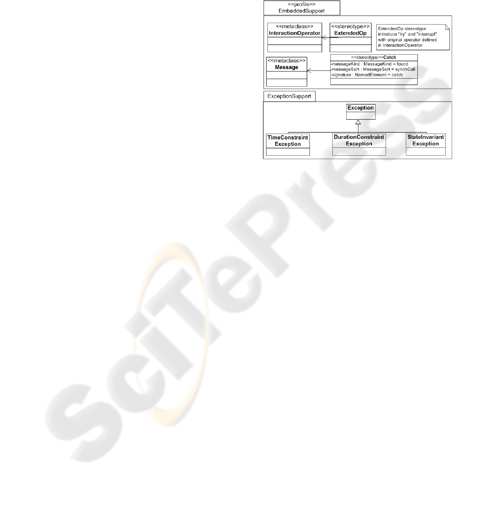
Figure 1: UML profile for extended sequence diagrams.
We extend the combined fragments of sequence
diagrams to describe the handling of exceptions and
interrupts. Extended interaction operators are ‘try’
for an exception handling and ‘interrupt’ for an
interrupt handling. An exception scenario is
recognized as an unsuccessful scenario. It occurs
when certain constraints are not satisfied. Generally,
an interrupt is controlled by system calls of the
operating system. However, we define an interrupt
as one of the events that occurs in the scenarios of
application level. When an exception or an interrupt
occurs, the execution of the current scenario is
stopped and a handling scenario is executed.
However, there are differences between the
handlings of two unexpected scenarios. The
occurrence of an exception is dependent on current
executing action. However, an interrupt occurs
regardless of the current action.
Figure 1 shows an UML profile (Eriksson 2003)
for our extension of exceptions and interrupts in
embedded software. A stereotype ‘Catch’ and a class
‘Exception’ are added for ‘try’ interaction operator.
The stereotype ‘Catch’ is a kind of the stereotype
‘Message’. The inherited classes from the class
‘Exception’ are selectively used in sequence
diagrams according to their properties.
ICSOFT 2006 - INTERNATIONAL CONFERENCE ON SOFTWARE AND DATA TECHNOLOGIES
258
3.1 Exception Handling Fragment
UML 2.0 sequence diagrams do not provide
notations for specifying or handling exceptions.
Therefore, we introduce a fragment ‘try’ which
handles exceptional behaviour. The processing of an
exception is considered in two aspects: a raising and
a handling (Storrle 2004).
The exception raising is described with three
parts: the trigger, the scope of readiness, and the
scope of preemption (Storrle 2004). Under our
notation, the trigger is one of ‘DurationConstraint’,
‘TimeConstraint’ and ‘StateInvariant’. The scope of
readiness is a place or a point that the exception can
arise, and the scope of preemption is the first
operand of ‘try’ fragment.
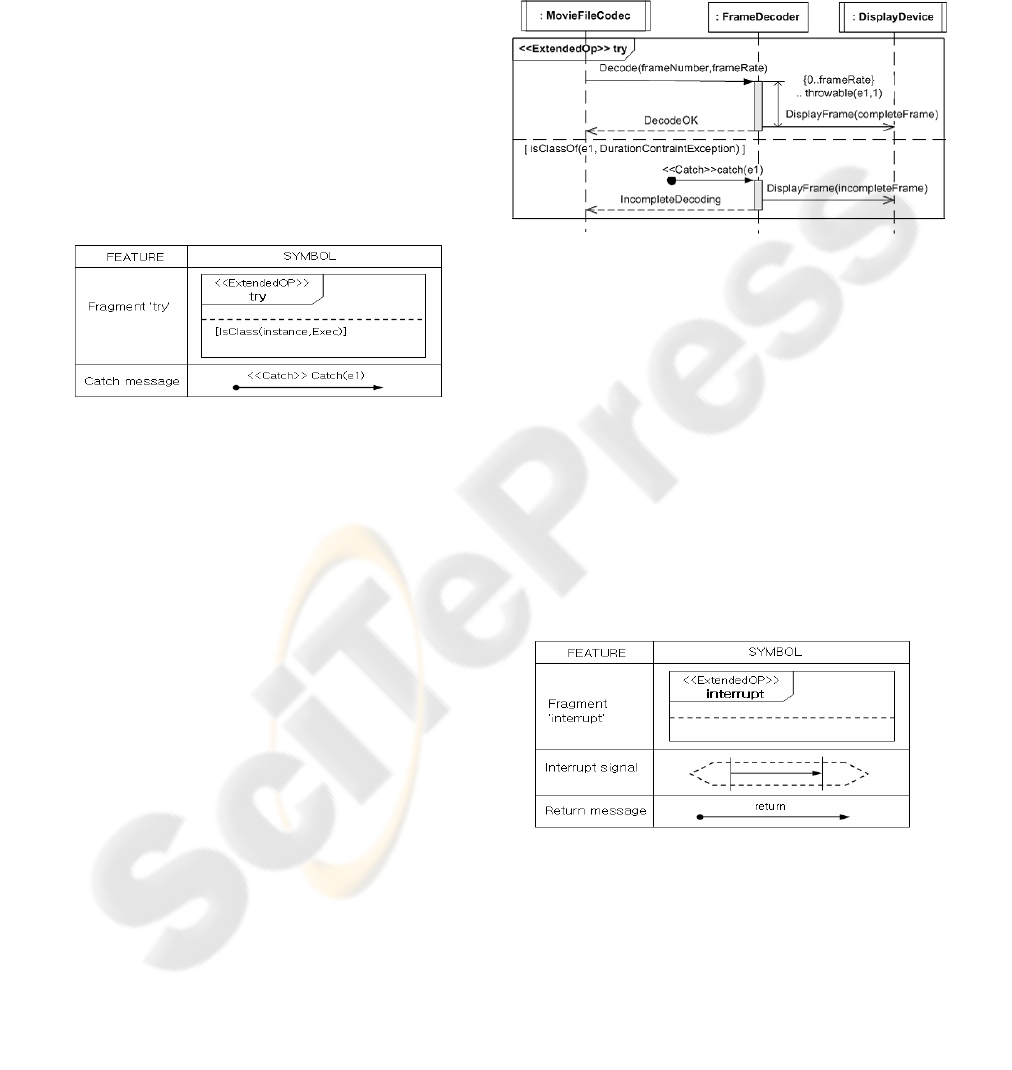
Table 1: Symbols used in interaction operator ‘try’.
An exception can occur during the execution of
normal scenarios within the ’try’ fragment. When
the exception occurs, an appropriate handling
scenario will be performed. Symbols used for an
exception handling ‘try’ are shown in Table 1.
– Interaction Operator ‘try’: The combined
fragment ‘try’ consists of two or more
fragments. The first fragment describes a
scenario in which exceptions may occur. Each
fragment of the rest describes the handling
scenario of each of those exceptions.
– Catch message: Catch message with stereotype
‘Catch’ recognizes Exception ‘e1’occurs in the
first fragment.
There are three kinds of exception types; Duration-
ConstraintException (DCE), TimeConstra
intException (TCE) and StateInvariantException
(SIE) (Goodenough 1975, Strohmeier 2001).
– DCE is on the handling of duration exception.
If an event is not progressed within a
predefined duration, DCE will occur.
– When an event does not happen at a particular
time, TCE occurs.
– SIE occurs when an invariant constraint is not
satisfied.
Figure 2 shows an example scenario of playing
movie files. Object ‘FrameDecoder’ decodes movie
files and sends the decoded data to ‘DisplayDevice’
object. If the decoding is not completed within
certain duration, a DCE exception will occur. The
bottom fragment in Figure 2 shows the handling of
such exception.
Figure 2: An example scenario of handling an exception.
3.2 Interrupt Handling Fragment
Although UML 2.0 sequence diagrams support the
representation of the interruptible behaviour, we
propose new notations to reduce the complexity of
models that handle interrupts. When modelling the
unexpected behaviour – i.e., an interrupt – using the
existing UML sequence diagrams, many diagrams
should be drawn. Thus we introduce an operator
‘interrupt’ which describes interruptible behaviours.
Symbols used for interrupt handling are described in
Table 2.
Table 2: Symbols used in interaction operator ‘interrupt’.
– InteractionOperator ‘interrupt’: The combined
fragment ‘interrupt’ consists of two or more
fragments. The first one describes a scenario
that is interruptible by some interrupt messages.
The others describe the handling scenarios for
those interrupt messages.
– Interrupt signal: The message which is placed
in a dotted long hexagon represents an interrupt
message.
MODELLING THE UNEXPECTED BEHAVIOURS OF EMBEDDED SOFTWARE USING UML SEQUENCE
DIAGRAMS
259
– Return message: After receiving an interrupt
signal, the original scenario is paused. The
return message makes the paused operations
resumed. If there is no return message, the
original scenario is not resumed.
If an interrupt message arrives, the execution of
a normal scenario stops and the execution control
flow moves to an interrupt handling region to
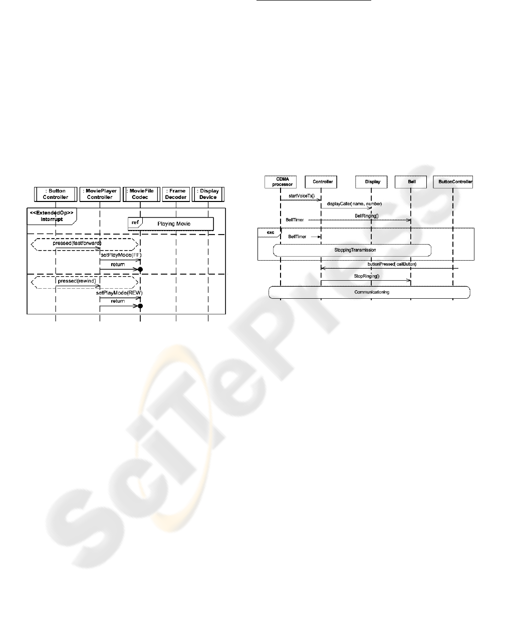
process the interrupt signal. Figure 3 shows an
example scenario of playing movie files with an
interrupt. It describes a scenario that ‘fast forward’
or ‘rewind’ button is pressed unexpectedly while the
movie is playing. If the ‘rewind’ button is pressed,
the execution of “Playing movie” interaction stops
and the bottom fragment is executed.
Figure 3: An example scenario with interrupt handling.
In UML 2.0 sequence diagrams, interrupts
could be described using fragment ‘alt’ (OMG 2004).
Since the modeler does not know exactly when an
interrupt would occur, he/she should put the ‘alt’
fragment into every single message. If there are
more than one interrupt, the number of the ‘alt’
fragments in the sequence diagrams is increased as
multiplied by the number of interrupts. For example,
if there is a scenario that contains 20 messages and 5
interrupts, then 100 ‘alt’ fragments would be shown
in the sequence diagrams.
4 COMPARISON OF MSC AND
SEQUENCE DIAGRAMS
In this section, we compare our extended sequence
diagrams with MSCs and UML 2.0 sequence
diagrams through an example scenario of a mobile
phone.
A Scenario of Mobile Phone
1. When there is a phone call, the caller’s
information is shown and the bell is ringing.
2. When the bell is ringing, the user can answer the
phone by pressing the call button.
3. The user can communicate with a peer through a
speaker and microphone.
4. If the user does not answer the phone after 15
seconds ringing, it will stop transmission.
5. If the user or peer presses a stop button, the phone
call is stopped.
Figure 4 shows the MSCs for a part of the
scenario. Expression ‘exc’ is used to describe which
exception occurs and how the exception is handled.
Figure 4: MSC model of the phone without interrupt.
In this case, the exception is that the user does
not press a button within 15 seconds after setting the
‘BellTimer’. If ‘BellTimer’ is timed out, ‘Stopping-
Transmission’ scenario is performed as an exception
handling.
Figure 5 shows the MSCs that describes the
whole steps of the scenario. An external event,
hanging the phone, is regarded as an interrupt signal.
MSCs do not have any notation for interrupt
handling. We use ‘exc’ expression to describe the
interrupt. If the user or peer presses a stop button
then the phone call is stopped. After pressing a stop
button, as an interrupt, designated handling scenario
is executed. Since it is not possible to know when
the user hangs the phone, the ‘exc’ expression
should be located after every message. It makes the
model difficult to read and hard to understand.
With our extended notations, the handling of
interrupts can be described in one sequence diagram
as shown in Figure 6, which describes the above
scenario. The ‘try’ fragment in the figure represents
the exception handling scenario that should be
executed when duration-constraint is violated. In
addition, the interrupt scenario that can be occurred
by user is described by ‘interrupt’ fragment
ICSOFT 2006 - INTERNATIONAL CONFERENCE ON SOFTWARE AND DATA TECHNOLOGIES
260
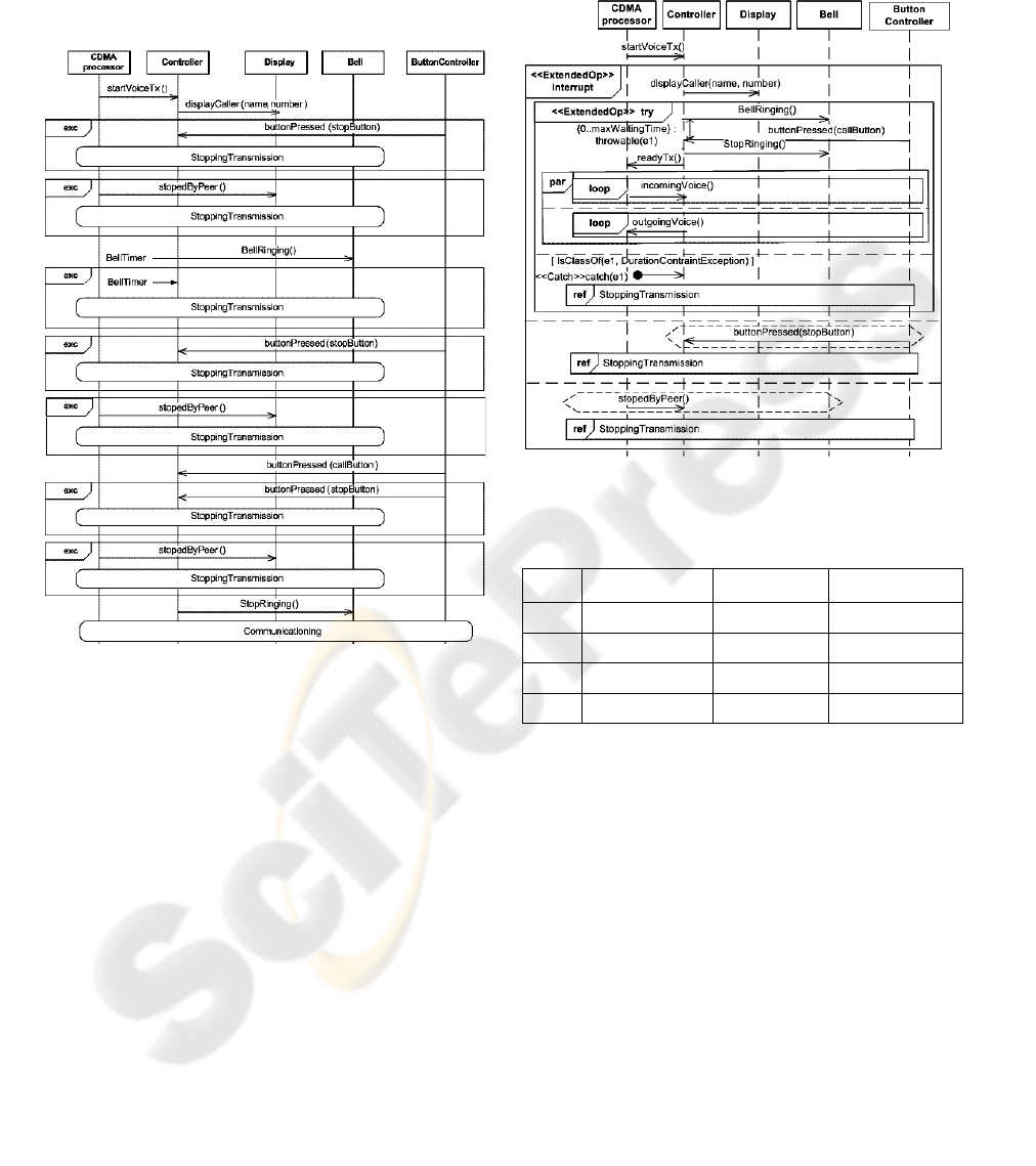
surrounding the whole behaviours. In the extended
sequence diagrams, the interrupt handling fragments
do not need to be located on every pair of messages
like Figure 5. The two extended notations can make
the sequence diagrams simple and help understand
the behaviours of the model easily.
Figure 5: A MSC model for the mobile phone.
With our extensions of sequence diagrams, we
model the following four example scenarios:
1. ATM(Automated Teller Machine) scenario
2. Call signalling scenario with one interrupt in
mobile phone
3. Call signalling scenario with two interrupt in
mobile phone
4. Simple message editing scenario with ‘loop’
fragment in mobile phone.
In the first scenario, an interrupt occurs by the
customer pressing a cancel button under normal
operation. The second scenario is in case of the
occurrence of an interrupt by hanging up the phone
call by receiver. The third scenario is that the phone
call is hanged up by receiver of caller. The last
scenario is in case of pressing OK button as an
interrupt while a simple message is editing within 50
characters.
For the above four scenarios, we summarize the
modelling results as shown in Table 3.
Figure 6: A extended sequence diagram for mobile phone.
Table 3: Example scenario modelling results.
no.
Number of messages
(generated by user)
Number of UML
sequence diagrams
Number of extended
sequence diagrams
1 15 14 1
2 6 6 1
3 6 12 1
4 1 49 1
From the Table 3, we observed that our extended
sequence diagrams provide some benefits in aspects
of simplicity, understandability, and intuitiveness
when describing unexpected behaviours. Also it can
reduce the effort of the modelling dynamic
behaviours in embedded software (Lee 2006).
5 RELATED WORK
Huget (Huget 2003) had introduced several
extensions to the sequence diagrams of Agent UML,
which is an UML extension for the interaction
protocol domains. He had presented a notation for
handling exceptions, a fragment named ‘exception’.
However, the way of handling the exceptions was
not mentioned. In our approach, we can describe the
MODELLING THE UNEXPECTED BEHAVIOURS OF EMBEDDED SOFTWARE USING UML SEQUENCE
DIAGRAMS
261

handling of exceptions as well as when they occur.
In UML, a ‘Signal’ is a metaclass defined as a
specification of an asynchronous stimulus
communicated between instances. An ‘exception’ is
a special ‘Signal’ occurring with fault stimulus such
as the violation of a preconditional or range
invariant (OMG 1998). Douglass (Douglass 1999)
had suggested the extended sequence diagrams that
represent an exception handling. From his
suggestion, a message stereotyped with ‘exception’
represents exceptional behaviours in embedded
software. The exception message is limited to
express negative scenario exception only.
6 CONCLUSION
In this paper, we presented an approach to extending
UML 2.0 sequence diagrams to model unexpected
behaviours of embedded software. Based on the
profile, we added modelling notations into UML 2.0
sequence diagrams in order to describe unexpected
behaviours in embedded software. Interrupts and
exceptions frequently occur under the operation of
embedded software. To model such unexpected
behaviours, we used new interaction operators ‘try’
and ‘interrupt’ for handling exceptions and
interrupts. The extensions in this paper help
modelers design embedded software clearly,
intuitively, and correctly.
There are some features to be considered.
Interrupts and exceptions could be lost during the
occurrences of other interrupts and exceptions. They
should be handled during other events. However, our
extensions could not cover those. It should be
controlled or handled by operating the system level.
Our final goal is the application of our
extensions to embedded software modelling for
multi-processor SoC platform. Sequence diagrams
for a multiprocessor system are more complex than
those of a single processor system. We are under
research about the modelling of unexpected
behaviours of embedded software that are executed
on multi-processor system.
ACKNOWLEDGEMENTS
This work was supported in part by IT Leading
R&D Support Project funded by Ministry of
Information and Communication, Republic of Korea
and support program supervised by the
IITA(Institute of Information Technology
Assessment).
REFERENCES
Douglass, B.P., 2004 Real-Time UML 3rd edition,
Addison-Wesley.
ITU, 1999. ITU Z.120, in Message Sequence Chart(MSC),
ITU-T: Geneva. p.126.
Mauw, S., Reniers, M.A., and Willemse, T.A.C., 2000.
“Message Sequence Charts in the Software
Engineering Process”, Computing Science Reports 00-
12, Department of Computing Science, Eindhoven
University of Technology
Damm, W., and Harel, D., 2001, “LSCs: Breathing Life
into Message Sequence Charts”, Formal Methods in
System Design.
Haugen, O., 2004, “Comparing UML 2.0 Interactions and
MSC-2000”, In Proceedings of SAM: SDL and MSC
fourth International Workshop, LNCS 3319.
Haugen O., 2001, “MSC-200 interaction diagrams for the
new millennium” Computer Networks, Volume 35,
Issue 6, May 2001.
Eriksson, H., Penker, M., Lyons B., and Fado, D., 2003,
UMLTM 2 Toolkit, Wiley.
Storrle, H., 2004, Semantics of Exceptions in UML 2.0
Activities, Technical Report, University of Munich.
Goodenough, J.B., 1975 “Structured exception handling”,
In Proceedings of the 2nd ACM SIGACTSIGPLAN
symposium on Principles of programming languages,
204-224, January, 1975, Palo Alto, California.
Strohmeier, A., Chachkov, S., 2001, “A side-by-side
comparison of exception handling in Ada and Java”,
ACM SIGAda Ada Letters, Volumn XXI, Issue 3.
OMG, 2004. UML 2.0 Superstructure Specification, Doc.
Ptc 04-10-02, Object Management Group October 8,
2004, from :
http://www.omg.org
H.J.Lee., 2006, “Exception and Interrupt Modelling in
UML 2.0 Sequence Diagrams for Embedded Software
Development”, Masters’ Thesis, KAIST KOREA.
Huget, M.P., 2003, “Extending Agent UML Sequence
diagrams”, AOSE 2003, LNCS 2586, 150-161.
OMG, 1998, UML Semantics Version 1.2, Object
Management Group from
http:///www.omg.org
Douglass, B., 1999, Doing Hard Time : Developing Real-
Time Systems with UML, Objects, Frameworks, and
Patterns, Addison-Wesley.
ICSOFT 2006 - INTERNATIONAL CONFERENCE ON SOFTWARE AND DATA TECHNOLOGIES
262
