
REVERSE ENGINEERING ELECTRONIC SERVICES
From e-Forms to Knowledge
Costas Vassilakis, George Lepouras, Akrivi Katifori
Department of Computer Science and Technology, University of Peloponnese, Terma Karaiskaki 22100, Tripoli, Greece
Keywords: e-Government, electronic services, rev
erse engineering, organizational knowledge.
Abstract: On their route to e-governance, public administrations have develop
ed e-services. Each e-service
encompasses a significant amount of knowledge in the form of examples, help texts, legislation excerpts,
validation checks etc. This knowledge has been offered by domain experts in the phases of service analysis,
design and implementation, being however bundled within the software, it cannot be readily retrieved and
used in other organizational processes, including the development of new services. In this paper, we present
an approach for reverse engineering e-services, in order to formulate knowledge items of a high level of
abstraction, which can be made available to the employees of the organizations. Moreover, the knowledge
items formulated in the reverse engineering process are stored into a knowledge-based e-service
development platform, making them readily available for use in the development of other services.
1 INTRODUCTION
In the past few years, governments are realizing e-
government policies and frameworks, which include
delivery of e-services for enterprises and citizens. In
this context, development of an e-service is usually
treated as an isolated project, thus information
extracted from domain experts in the analysis phase
is recorded as low level “user requirements”, rather
than as high-level knowledge (Vassilakis, 2003).
This practice leads to suboptimal results since:
• the “softwa
re specifications” format is
inappropriate for knowledge sharing among the
organization’s employees. Employee groups that
could benefit from the knowledge amassed during
the analysis phase include domain experts, seeking
information on relevant subjects and help desk
workers, who could use this knowledge to provide
information and guidance to users of the e-service.
• t
he knowledge offered by domain experts, includes
a number of examples, explanations, related
legislation and so forth; in this form, it could be
used to tackle the “lack of expert assistance” usage
barrier for e-services identified in (Vassilakis,
2005), according to which users refrain from using
e-services because no adequate help is available.
• soft
ware specifications produced for an e-service
are usually considered as pertinent to the specific
service only; this reduces opportunities for reusing
the knowledge for developing other services (e.g.
re-using the personal details portion of a form).
To tackle these deficiencies, organizations are
ad
opting either (a) knowledge management (KM)
platforms, for recording knowledge in explicit
format and facilitate searching, browsing and
sharing and (b) e-service development platforms,
which can leverage component reusability across
services. For already developed services, however,
the original knowledge has already been mapped to
software specifications and artifacts (HTML forms,
JavaScript/back-end code, database schemata etc),
therefore these services must either remain “isolated
islands” or be remodeled in the chosen platform
(KM or e-service development platform), incurring
thus additional effort and cost.
In this paper we present a method for reverse
engi
neering software components of developed e-
services, and using the individual elements identified
in the reverse engineering process to synthesize
artifacts of higher levels of abstraction. These
artifacts encompass aspects useful both for KM and
e-service development, being consequently suitable
both for knowledge sharing and dissemination
within the organization, as well as for developing
new services. The presented method has been
applied to produce artifacts suitable for importing
into the SmartGov platform, a knowledge-based
development environment for public sector online
services (Georgiadis, 2002), (SmartGov, 2004).
273
Vassilakis C., Lepouras G. and Katifori A. (2006).
REVERSE ENGINEERING ELECTRONIC SERVICES - From e-Forms to Knowledge.
In Proceedings of the First International Conference on Software and Data Technologies, pages 273-278
DOI: 10.5220/0001313202730278
Copyright
c
SciTePress

The rest of the paper is organized as follows:
section 2 presents related work. Section 3 introduces
the SmartGov platform, while section 4 elaborates
on the reverse engineering process. Finally, section 5
concludes the paper and outlines future work.
2 RELATED WORK
Reverse engineering is a process of examination (as
opposed to alteration), directly supporting the
essence of program understanding: identifying
artifacts, discovering relationships, and generating
abstractions (Chikofsky, 1990). Reverse engineering
methods and techniques are used for three canonical
activities, namely data gathering, knowledge
management and information exploration (Tilley,
2000). The activity of knowledge management in
particular, refers to capturing, organizing,
understanding, and extending past experiences,
processes, and individual know-how. In this context,
the reverse engineering process produces artifacts
that, if properly managed, could be shared at various
levels, e.g. development team or department, serving
thus as an active repository of corporate knowledge
(Kazman, 1998). Regarding the application of
software reverse engineering techniques on web
applications, notable activities reported insofar
include (DiLucca, 2004), which aims to the
construction of UML diagrams so as to support the
maintenance and evolution of web applications;
(Paganelli, 2003) describes a method for extracting
task models from web pages, in order to reconstruct
the underlying interaction design; finally RetroWeb
(Essanaa, 2004) aims at providing a description of
the informative content of the site at various
abstraction levels: physical, logical and conceptual.
3 THE SMARTGOV PLATFORM
The SmartGov platform offers functionality for
managing knowledge and validation rules, creating
objects, designing forms and services and deploying
them. The central concept in the SmartGov platform
is that of Transaction Service Elements (TSEs).
TSEs are in fact widgets, which can be used as
building blocks for e-services. Contrary though to
user interface widgets, TSEs extend beyond visual
appearance: they can contain metadata and domain
knowledge. Metadata include the object's type,
labels, allowable values, validation checks, and on-
line help, while domain knowledge includes
relationships to other elements, documentation,
legislation information etc. Other concepts in the
platform are TSE groups (assemblies of individual
TSEs which can be managed collectively), forms
(canvases on which TSEs and TSE groups are
placed) and transaction services (TSs – collections
of forms offering a specific service). Similarly to
TSEs, instances of these concepts contain metadata
and domain knowledge. Metadata elements in these
concepts vary according to the concept type, e.g.
metadata for a TS include the authentication method
and whether modification of submitted documents is
allowed. The SmartGov platform also offers
functionalities for establishing links among instances
of the modeling concepts (TSEs, groups, forms and
TSs), formulating thus a semantically rich network
of elements, which can be browsed or queried by
platform users. For more information on the
SmartGov platform, refer to (SmartGov, 2004).
4 REVERSE ENGINEERING
E-SERVICES
In this section we present the rules employed for
electronic artifact identification and composition.
The aim of this reverse engineering approach is to
formulate semantically rich artifacts (TSEs, TSE
groups, forms and TSs), with each one of them
encompassing visual characteristics, knowledge
(help texts, examples, etc), business rules (validation
checks) and relations with other elements. The
heuristics for combining individual HTML form
elements into e-service artifacts exploit the structure
and nesting of HTML tags, naming conventions and
element proximity. In the rest of this section, we first
present the common artifact patterns as they appear
in transactional services; these patterns dictate the
operation of the heuristics for artifact identification
and composition, which is discussed subsequently.
4.1 Artifact Patterns in e-Services
When designers create the pages comprising a
service, they arrange elements in ways that are
meaningful and usable for service users. In order to
extract patterns for these arrangements, more than
50 online services from different countries were
examined.
The services used in this analysis were
selected from well-established government portals
for online services, including the US portal
(www.firstgov.gov), the UK online service directory
(www.direct.gov.uk) and the Singapore e-
government services for citizens catalogue
(www.ecitizen.gov.sg). The layout of printed forms
ICSOFT 2006 - INTERNATIONAL CONFERENCE ON SOFTWARE AND DATA TECHNOLOGIES
274
has also been considered, since e-services have been
found to often mimic the appearance of their paper-
based counterparts. The on-line service directories
listed above were used as the primary source of
services and forms; other sources though were
considered as well (e.g. Cyprus’ Ministry of Finance
(www.mof.gov.cy), Greece’s on-line taxation portal
(www.taxisnet.gr) as well as EU directives and
samples (europa.eu.int/comm/taxation_customs)).
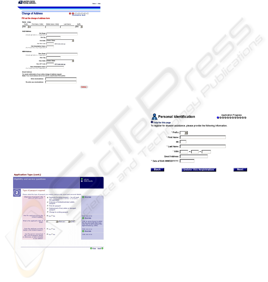
Figure 1: A common layout for service elements.
A common layout for service elements is shown
in fig. 1, where we can identify the following areas:
1. a header, including the agency logo, links to the
agency’s home page and generic help, as well as a
graphic acting as a separator,
2. the main body, which includes short introduction
of the form, the actual input elements (grouped
here in four areas) and their explanations,
3. and a footer, including navigational controls
(Continue button) and a service-specific help link.
Figure 2: Help texts and additional help links.
Input elements have been organized into groups,
with each group having a header (e.g. Name, OLD
address). A help hyperlink (for the “Name” group)
and/or some text for the group as a whole (e.g. in the
“Email Address” group) may also be present. Within
a group, input elements may be laid out either (a)
horizontally, with their descriptions being placed
above (below) them (e.g. the “Name” group) or (b)
vertically, with their descriptions being placed on
the left of the element (more rarely, on the right).
In both layouts, help texts and additional help or
utility links for individual input elements may be
present, which may be placed besides the field
description or the input element. Examples of help
texts and additional help links are illustrated in fig.
2, while an example of a utility link is the “Zip Code
lookup”, next to the zip code inputs in fig. 1. In
some cases, a particular data item may be collected
using more than one input element, as is the case of
the date of birth (fig. 2) and the “SSN” data item
(fig. 3). Typically, this technique is used for
registration numbers (SSN, bank account numbers,
license plates etc), as well as dates. In such cases,
the constituent input elements are usually juxtaposed
on the layout, with the possible intervening of a
separator (dash, slash, space and so forth). Notice
that the overall form layouts in figs. 2 and 3 follow
the pattern identified for fig. 1. An additional
commonplace practice is the use of the asterisk (*)
to denote mandatory fields (figs. 2 and 3). The
asterisk is most usually placed next to the input area
or next to the label.
Figure 3: An item spanning across more than one
elements.
4.2 Artifact Identification &
Creation
The phase of artifact identification begins with the
specification of the HTML pages that comprise the
service. The pages may be read directly from the
web server hosting the service, or from a local file
system. This phase includes application of heuristics
that attempt to recognize the patterns described in
the previous section within the HTML pages. For
each pattern identified, a proper artifact is
constructed, encompassing all information pertinent
to it; if appropriate, links to other artifacts are also
established. Tag nesting, JavaScript code associated
with HTML page elements and naming conventions
are additional sources of information for the reverse
engineering process.
REVERSE ENGINEERING ELECTRONIC SERVICES - From e-Forms to Knowledge
275

Before the application of heuristics, the reverse
engineering software (RES) creates the object model
of each page, i.e. a tree-structured representation of
the page components (tables, divisions, forms, fields
etc. The HTMLParser (htmlparser.sourceforge.net)
package was chosen for this purpose. The heuristics
for each type of component (TSE, TSE group, form,
and TS) are presented in the following paragraphs.
4.2.1 Identifying Transaction Service
Elements
A transaction service element (TSE) in the
SmartGov platform is a compound object
encompassing the input area and its properties
(HTML input type, size, maximum length, initial
value), the input area label, help texts (commonly
provided as hyperlinks or as extended in-place text),
the validation rules that apply to the values entered
(data type, mandatory input, allowable ranges etc)
and, finally, its relationships with other elements.
The first task towards TSEs identification is to
locate the widgets allowing for data input. HTML
provides four basic input widgets, namely input,
select, textarea and button. For each such construct a
respective TSE is created, except for the case of
inputs of type radio, for which a single TSE is
created for all input instances with the same value
for the name attribute. The reverse engineering
process subsequently locates information for the
additional aspects of the TSE as follows:
Firstly, the TSE label is determined. The form is
initially scanned for a label element whose for tag
matches the input element name (e.g.
<label
for="fname">First Name</label>), or for a
label element enclosing the input area definition
(e.g.
<label>First Name <input
type="text" name="fname"></label>). If
such an element is found, the text specified in the
label element is used as the TSE label. If no such
label is found, the RES attempts to determine the
label by its positioning relative to the input area: the
label may be placed on the left of the input area
(figs. 2, 3 and bottom half of fig. 1), or above the
input area (upper half of fig. 1). Note that the text
may be formatted using tables, thus “left” does not
necessarily refer to HTML code immediately
preceding the input tag, but may be the text included
in the table cell appearing on the left of the field
under examination. The RES takes into account the
case that an extra column, indicating whether the
field is mandatory or not, intervenes between the
input area and the label field (fig. 2).
Afterwards, the help items for the field are
located. The help items may be located at the right
of the input area, either as directly following HTML
code (fig. 1) or within an adjacent table cell (fig. 2).
In some cases, only a hyperlink may be present
which has to be clicked to display the help content.
In such cases, the RES retrieves the content pointed
to by the help anchor, and packs this content within
the TSE; the label text (determined in the previous
step) is also scanned for presence of hyperlinks. If
such hyperlinks are found, the content pointed to by
each hyperlink is extracted and packed with the TSE
as a help item. This step may produce multiple help
items for a single TSE. Additional help items may
be determined from code analysis (described below).
The next step is to extract an initial indication
whether a TSE is considered mandatory or not. The
presence of an asterisk either packed within the label
(at its beginning or end – fig. 3) or as a separate
table column (fig. 2) is used as such an initial
indication. An additional check to determine
whether some input element is mandatory or not is
performed in the code analysis phase (see below).
Subsequently, the default value for the input area
is determined by examining the settings of the
HTML attributes associated with the input area (e.g.
the “value” attribute for text boxes and buttons, the
“checked” attribute for check boxes etc). The values
of the “maxlength”, “size”, “rows” and “cols”
attributes, whenever present, are also extracted and
bundled as properties of the TSE under construction.
For input elements with a closed set of values
(such as select widgets and radio buttons), the set of
values is examined to determine the data type of the
input element. If all the values within the set are of
the same type (integers, floats, dates, etc), the data
type of the TSE under construction is set
accordingly; otherwise, the data type is set to
“string”. Data type inference for input elements with
an open set of values (free user type-in) is handled
through code analysis (described below).
The TSE properties listed above can be directly
determined form attributes values of the input
elements or from text placement in relation to the
input element. However, some important aspects of
TSEs, namely the data type, whether a TSE is read-
only or not, as well as validation checks may not be
directly modeled as attribute values; instead, e-
service developers use JavaScript to provide these
features. In order to determine these features, the
RES analyzes the JavaScript code associated with
input element events. This analysis may also reveal
additional help items and supplementary indications
on whether the TSE is mandatory or not. JavaScript
code analysis is based on heuristics, since rigorous
semantic analysis was considered exaggerate for the
issues at hand, taking also into account that the
ICSOFT 2006 - INTERNATIONAL CONFERENCE ON SOFTWARE AND DATA TECHNOLOGIES
276
results will be reviewed by humans before being
used for code generation. These heuristics are:
1. if the “onFocus” and “onSelect” event handlers of
the input element are present and contain code
that moves the focus away from the field
(typically this is performed using the this.blur()
method or by moving the focus to another field
through the anotherfield.focus() method), then the
TSE is characterized as “read-only”. Note that
this is complementary to checking for existence
of the “readonly” and “disabled” input element
attributes, i.e. if either of the checks succeeds, the
TSE is characterized as “read-only”.
2. if the JavaScript code within the page contains
instructions that compare the value of the element
with the empty string (elem.value == “” or
elem.value.length == 0) and emit a message if the
condition is true, then the TSE is considered
mandatory. Code patterns that trim the spaces
from the element value and compare the result
with the empty string (e.g. trim(element.value)
== “”) are also taken into account in this check.
3. if the “onFocus”, “onSelect” and “onMouseOver”
event handlers of the input element exist and
contain code displaying text on the browser status
bar (e.g. onfocus="javascript:window.status =
'Enter net income'") or at some other page
element (e.g. onfocus= "javascript:document
.getElementById('helpArea').innerHTML='Enter
net income'") then the displayed text is considered
an extra help item for the TSE under construction.
4. if the “onChange” event handler exists, then the
code in it is scanned for function invocations
whose argument list does not reference other
fields. The name of each such function is
examined to determine whether it is a compound
word, whose first component is one of the words
“check”, “is”, “valid”, “validate”, “verify”, while
the second component being a data type name or
a synonym for it (number, date, integer, float,
numeric and so forth) –e.g. onchange="
checkNumber(this, 'Price should be a number');".
If a match is found, the data type for the TSE
under construction is set accordingly. The whole
JavaScript code of the page is also scanned for
conditions of the form if (checkNumber(price)...),
to cater for cases that user input validation is
deferred until form submittal, rather than being
performed synchronously with data typing.
5. code associated with the “onChange” event
handler and that (a) does not reference other
fields (b) does not meet the naming criteria of
item (4) and (c) emitting a message, is recorded
as a validation check for the TSE. This code may
implement any validation check e.g. value range,
data format and so on. Conditions of if statements
anywhere within the JavaScript code of the page
that reference only the specific TSE are added
-together with the associated code block- to the
list of validation checks associated with the TSE.
At this stage, all data regarding the TSE artifact
have been collected, and the TSE is finalized.
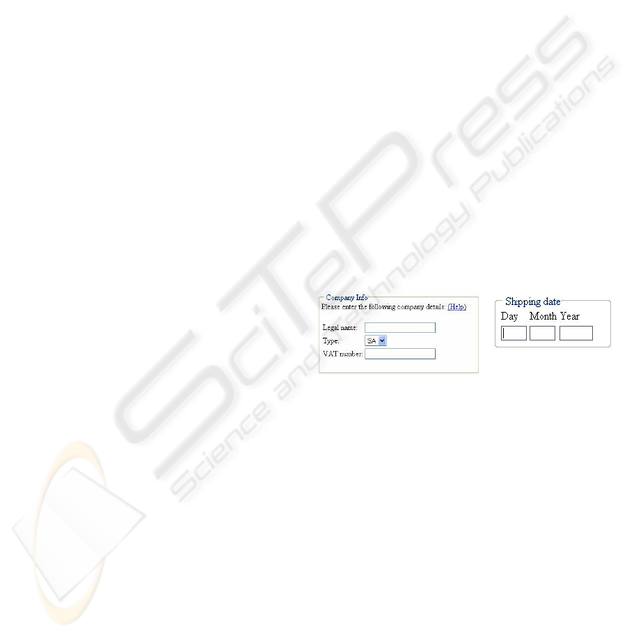
4.2.2 Identifying TSE Groups
The HTML standard provides the fieldset tag for
specifying groups of fields. Browsers supporting this
feature draw a border surrounding the input areas
(fig. 4) to provide a visual clue that these elements
are logically associated. The field set may be
assigned a label using a nested legend tag. The RES
identifies such constructs and for each one of them
creates a TSE group artifact, which is automatically
linked with the individual TSEs it contains. The TSE
group description is derived from the contents of the
enclosed label element, while extra text occurring
within the fieldset construct and not directly
associated with a specific TSE (e.g. the Please
enter… phrase in fig. 4) is considered as a detailed
description for the TSE group. Hyperlinks occurring
within such extra text are considered as help items
for the TSE group as a whole. The TSE group under
construction is finalized by adding to it the pertinent
validation checks. These are identified as follows:
Figure 4: Rendering of fieldset constructs.
• the onChange event handler of the TSE elements
belonging to the group are scanned for code that
involves two or more elements of the group (e.g.
onChange="check_date(day, month, year)
") but
not referencing any field outside the group.
• the page’s JavaScript is scanned for if statements’
conditions involving two or more members of the
TSE group, but not referencing any field outside
the group. These conditions, together with the
associated action blocks, are added to the list of
validation checks associated with the TSE group.
At this stage, all data regarding the TSE group
have been collected, and the artifact is finalized.
The fieldset tag is not however the predominant
approach for implementing field groups: tables are
usually employed instead since (a) not all browsers
support the fieldset tag and (b) tables provide more
flexibility for laying out titles, borders, fields etc.
The RES deduces field groups by identifying table
REVERSE ENGINEERING ELECTRONIC SERVICES - From e-Forms to Knowledge
277

segments: a table segment comprises of a header
row containing only text (cf. fig. 1, rows “OLD
Address”, “NEW Address”, “Email address” and
Fig. 2, row “Type of passport”), followed by a
number of body rows, containing labels, input
widgets and help texts. For each table segment, a
TSE group is created; the text within the header row
is used as the TSE group description, and links to the
TSEs corresponding to the input fields within the
text segment are established. Processing for help
items and validation checks proceeds as described
for TSE groups defined using the fieldset tag.
4.2.3 Creating Form Artifacts
For each file processed, the RES produces one form
artifact. The form artifact is linked to the TSE and
TSE group artifacts it contains, while the form
header and form footer areas (i.e. HTML code
before the first TSE/TSE group and HTML code
after the last TSE/TSE group respectively) are used
to populate the respective elements of the form
artifact. Hyperlinks within the form header and
footer are exploited to create help items for the form,
as previously described for TSEs. Validation checks
involving multiple fields not belonging to the same
TSE group are finally added to the form artifact, as
validation checks pertaining to the form as a whole.
4.2.4 Creating the Transaction Service
Artifact
For each invocation, the RES constructs a single TS
artifact. This contains links to the service forms, and
each such link is tagged with the order that the form
appears in the service. Once the TS artifact has been
formulated, all artifacts are imported into the
SmartGov platform, made thus available for use in
developing other services. The reverse engineered
service itself may be re-generated, by invoking the
SmartGov platform’s Integrator module.
5 CONCLUSIONS
In this paper we have presented a method for
reverse-engineering e-services into artifacts of
higher level of abstraction, which may be used for
knowledge representation and sharing, and as
reusable components for development of other
services. Future work will include co-examination of
the back-end code (e.g. PHP, JSP), to reveal more
validation checks, handling of multilingual service
aspects and generalization of “quite similar” artifacts
for the creation of more generic artifact templates.
ACKNOWLEDGEMENTS
This work has been partially funded by the
“Intelligent Historical Archive Document
Management”/PENED 2003 project.
REFERENCES
Adobe (2005). Adobe Government Forms. Retrieved from
http://www.adobe.com/government/forms
BEA Systems (2005). Bea Logic Workshop. Retrieved
from http://www.bea.com/framework.jsp?CNT=
index.htm &FP=/content/products/weblogic/workshop
Chikofsky, E. and Cross, J (1990). Reverse Engineering
and Design Recovery: A Taxonomy, IEEE Software
vol. 7, no. 1, pp. 13–17.
Di Lucca,G. A., Fasolino, A. R., Tramontana, P. (2004).
Reverse engineering web applications: the WARE
approach. Journal of Software Maintenance and
Evolution: Research and Practice, Volume 16, Issue
1-2, pp. 71–101.
Essanaa
S. B., Lammari, N. (2004). RetroWeb: A Web
Site Reverse Engineering Approach. Proceedings of
Web Engineering: ICWE 2004, Munich, Germany,
July 26-30, pp. 306–310.
Georgiadis P. Lepouras G., Vassilakis C. et al. (2002). A
Governmental Knowledge-based Platform for Public
Sector Online Services. Proceedings of EGOV 2002,
pp. 362-369
Kazman, R., Woods, S., Carrière J. (1998). Requirements
for Integrating Software Architecture and
Reengineering Models: CORUM II. Proceedings of
the 5th Working Conference on Reverse Engineering,
IEEE Press, Los Alamitos, CA, pp. 154–163.
SmartGov Consortium (2004). SmartGov Project
Deliverable D13: Final Project Report. Retrieved from
http://www.smartgov-project.org
Tilley, S. (2000). The canonical activities of reverse
engineering. Annals of Software Engineering, vol. 9,
pp. 249-271.
Vassilakis, C., Laskaridis, G., Lepouras, G., Rouvas, S.,
Georgiadis, P. (2003). A framework for managing the
lifecycle of transactional e-government services.
Telematics and Informatics vol. 20, pp. 315–329
Vassilakis, C., Lepouras, G., Fraser, J., Haston, S.,
Georgiadis, P. (2005). Barriers to Electronic Service
Development, e-Service Journal, vol. 4(1), pp. 41-63
ICSOFT 2006 - INTERNATIONAL CONFERENCE ON SOFTWARE AND DATA TECHNOLOGIES
278
