
INFORMATION SYSTEM DESIGN AND PROTOTYPING USING
FORM TYPES
Jelena Pavićević
Faculty of Mathematics and Computer Science, University of Montenegro, Cetinjski put bb, 81000 Podgorica,
Serbia and Montenegro
Ivan Luković
Faculty of Technical Science, University of Novi Sad, Trg D. Obradovića 6, 21000 Novi Sad, Serbia and Montenegro
Pavle Mogin
Victoria University of Wellington P.O. Box 600, Wellington, New Zealand
Miro Govedarica
Faculty of Technical Science, University of Novi Sad, Trg D. Obradovića 6, 21000 Novi Sad, Serbia and Montenegro
Keywords: Form Type, Prototype, Inform
ation System Design, Relational Database Schema, CASE tool, XML,
IIS*Case.
Abstract: The paper presents the form type concept that generalizes screen forms that users utilize to communicate
with an information system. The concept is semantically rich enough to enable specifying such an initial set
of constraints, which makes it possible to generate application prototypes together with related implementa-
tion database schema. IIS*Case is a CASE tool based on the form type concept that supports conceptual
modelling of an information system and its database schema. The paper outlines a way how this tool can
generate XML specifications of application prototypes of an information system. The aim is to improve
IIS*Case through implementation of a generator which can produce an executable prototype of an informa-
tion system, automatically.
1 INTRODUCTION
A development of CASE tools that support information
system (IS) and database (db) design may be based on
the form type concept, which enables formulating a
methodological approach that allowes a designer to
specify screen forms of transaction programs and, indi-
rectly, define an initial set of attributes, constraints,
business rules and procedures. During the automated
process of the design, the set of form types will be
transformed into an implementation db schema. As a
result, formal design specifications of an IS may be
generated. Basic concepts and formalisms, this ap-
proach relies on, have been founding from late 80’s.
Meanwhile, we have established and constantly im-
proved a theoretical model, which is based on a method
of developing ISs and db schemas by gradual integra-
tion of designed subsystems (Luković, 2002; Luković,
2003; Mogin, 1995). The whole idea is implemented in
IIS*Case. IIS*Case is a CASE tool designed to support
modelling IS software, db schemas, and generating the
appropriate formal specifications. Our aim is to im-
prove IIS*Case through the implementation of a ge-
nerator which can produce an executable prototype of
an IS, automatically. At the time being, functionalities
of IIS*Case are extending with a generator able to pro-
duce such prototypes in the Java programming envi-
ronment. The paper presents the form type concept and
outlines a way how IIS*Case can generate software
prototypes of an IS, by using form type specifications.
157
Pavi
´
cevi
´
c J., Lukovi
´
c I., Mogin P. and Govedarica M. (2006).
INFORMATION SYSTEM DESIGN AND PROTOTYPING USING FORM TYPES.
In Proceedings of the First International Conference on Software and Data Technologies, pages 157-160
DOI: 10.5220/0001308201570160
Copyright
c
SciTePress
2 THE FORM TYPE
The form type concept is introduced in (Mogin,
2004; Pavićević, 2005). It generalizes document
types, i.e. screen forms that users utilize to commu-
nicate with an IS. Using this concept, a designer
specifies screen forms of transaction programs and,
indirectly, creates an initial set of attributes and con-
straints that will be embedded in generated db
schema and design specification of the IS.
A form type is a named tree structure, whose
nodes are called component types. Each component
type is identified by its name in the scope of the form
type, and has nonempty sets of attributes with associ-
ated domains, and constraints. The set of constraints
is a union of sets of keys, unique constraints, and tu-
ple constraints. Sets of unique constraints and tuple
constraints may be empty.
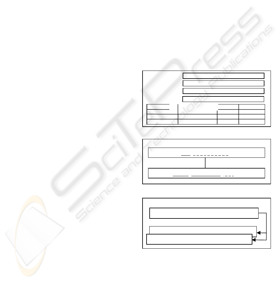
Example 1. Figure 2 shows the structure of a
form type F, which generalizes the screen form in
Figure 1. The form type consists of two component
types: EMPLOYEE and PROJECT, which are
graphically represented by rectangles. Sets of attri-
butes of component types are shown in rectangles.
Attributes underlined with solid lines indicate com-
ponent type keys, whereas attributes of unique con-
straints are underlined with dashed lines.
At the abstraction level of instances, each form
type has its instances. Each form type instance
represents a particular document that user creates,
modifies, or uses to communicate with the IS. In our
approach, a form type instance is a tree structure
over the instances of component types. Each instan-
ce of the root component type is, at the same time,
the instance of a form type itself. It is identified by a
value of any of the root component type keys. If a
component type N
i
is directly superordinated to the
component type N
j
, then each (child) instance of N
j
is identifiably associated with exactly one (parent)
instance of N
i
and each instance of N
i
may be related
to more than one instance of N
j
. Each instance of N
j
is identified by a value of any key of N
j
, in the scope
of its parent instance.
A possible number of instances of the component
type within its parent instance is specified by choosing
one of the two options: 0-N, or 1-N. The option 0-N
means that the set of instances of the component type
may be empty, while 1-N specifies that there always
exists at least one instance of the component type,
within its parent instance. The maximal number of
child instances is always unbounded.
Example 2. Figure 3 shows an instance of the
form type from the Figure 2. Each instance of the
component type EMPLOYEE from Figure 2 repre-
sents a particular screen form aimed at browsing and
editing records about employee’s engagement in
different projects. Each EMPLOYEE record is iden-
tified by a value of key PID. Name+Surname i
s a
unique co
nstraint. It means that every non null value
of two-tuple Name+Surname must be unique among
all EMPLOYEE records. Each instance of the com-
ponent type PROJECT represents one of projects in
which the employee is engaged. Each employee may
participate in several projects. Each record about
employee’s engagement in the project is identified
by values of keys ProjID and ProjectName, but only
in the scope of the appropriate, exact value of the
parent component type key PID. For each project, an
employee may have a role associated with her/him
in the project team, defined by a value of the
attribute Role. Role is a unique constraint of the
component type PROJECT, whi
ch means that each
non null value of
Role must be unique among all
PROJECT records of an employee identified by a
value of PID.
NAME
PROJECT NAME
ROLE
STATUS
SURNAME
TITLE
PROJECT ID
PID
Figure 1: A screen form.
EMPLOYEE
PID
Figure 2: The form type for the form in Figure 1.
Figure 3: An instance of the form type in Figure 2.
3 IIS*CASE AND THE FORM
TYPE
Figure 4 shows the main screen form of IIS*Case
(Integrated Information Systems*Case, V.6.0), a CASE
PROJECT
, Name, Surname, Title
ProjID, ProjectName, Role, Status
EMPLOYEE
1, Backup System, Developer, pending
123456, John, Smith, System Engineer
PROJECT
2, Billing System, Project Manager, finished
ICSOFT 2006 - INTERNATIONAL CONFERENCE ON SOFTWARE AND DATA TECHNOLOGIES
158
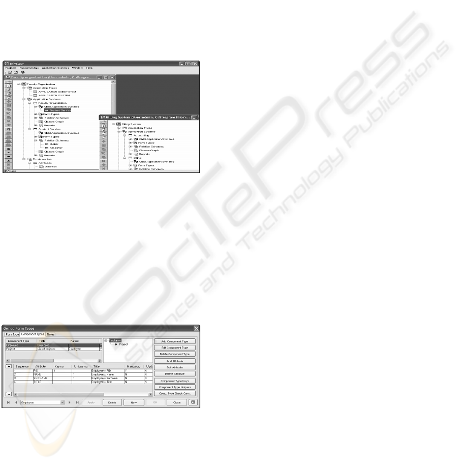
tool based on the form type concept. IIS*Case is
designed to provide complete support for developing
db schemas, which are complex with regard to the
number of concepts used and to generate design
specification of ISs. Having an advanced knowledge of
IS and db design is not explicitly needed for using
IIS*Case. IIS*Case gives an intelligent support during
the design process. IIS*Case supports:
• Conceptual modelling of a db schema,
• Automated design of relational db subschemas in
the 3rd normal form,
• Automated integration of relational db subsche-
mas, and
• Generating XML specifications of the information
system.
Figure 4: IIS*Case – Main Screen Form.
All the concepts and methods that IIS*Case uses,
and full specifications of implemented algorithms,
are described in (Luković, 2003; Mogin, 1995;
Mogin 2004, Pavićević 2005). Design of a complex
IS in IIS*Case is organized by its decomposition
onto application systems. Application system is a
specification of a subsystem of the future IS that
contains a set of form types and may include one or
more child application systems (Govedarica, 2004,
Pavićević 2005).
Figure 5: IIS*Case – Screen Form for specifying form
types.
IIS*Case imposes strict structuring rules for form
types. Using the screen forms, one of which is
shown in Figure 5, designers are able to specify
form types of various structures. They may define
component types, their sets of attributes and the con-
straints: key, unique, and check constraints. A form
type is organized as a tree structure of component
types.
4 APPLICATION PROTOTYPING
In (Govedarica, 2004), a method for design applica-
tion prototypes based on XML is presented. The
method proposes generating platform independent
XML specifications of an IS. Further XSL transfor-
mations, applied on those XML specifications, pro-
duce an executable prototype of the IS in the Java
programming environment.
The model represented in (Govedarica, 2004) is
based on User Interface Markup Language (UIML).
Application prototypes are specified by means of
XML, and after that, they are automatically trans-
formed into UIML specifications. XML specifica-
tions of the prototypes are platform independent,
while the resulting UIML specifications are platform
dependent. The prototypes may be interpreted by a
Java Render. Java Render by Harmonia Incorpora-
tion® is chosen programming and run-time envi-
ronment. Implementation of this method in IIS*Case
will provide the automated generation of fully func-
tional application prototypes.
5 XML SPECIFICATION OF THE
FORM TYPE
IIS*Case generates valid XML documents
containing design specifications of the form types,
and generated db schemas. Such documents, to-
gether with XML specifications of application sys-
tems, are integrated into an initial XML specifica-
tion of the information system. XML specifications
are independent of any run-time environment and
the repository structure of any CASE tool.
The process of generating prototypes is based on
using XSL transformations and Java programming
environment. The next research step is to create an
XSL transformation that will be able to transform
the initial XML specifications into final UIML
documents. IIS*Case will be able not only to gene-
rate, but also to interpret final XML (UIML) specifi-
cations of IS as fully functional prototypes.
6 CONCLUSION
The form type concept is semantically rich enough
to enable specifying such an initial set of constraints,
which makes it possible to generate application
INFORMATION SYSTEM DESIGN AND PROTOTYPING USING FORM TYPES
159

prototypes and underlying implementation db
schema, automatically.
From the designer’s point of view, IIS*Case of-
fers a simple and natural way for defining the initial
set of attributes and constraints of various kinds. By
the knowledge of the authors, it is an original ap-
proach, which cannot be found in the same form in
similar tools. It simplifies defining the rules, con-
straints, and procedures, particularly if the designed
software and db schema of an IS are complex with
regard to the number of concepts spanned. By the
experience of the authors, these design activities
usually require a large intellectual effort and an ad-
vanced knowledge in the IS and db area, but real
designers do not always posses those skills. We be-
lieve that IIS*Case may significantly help them in
overcoming IS and db schema complexity.
Implementation of the application prototyping
generator in IIS*Case will enable generating fully
functional and highly standardized application pro-
totypes, by supporting a design method and the de-
sign activities that are almost completely automated.
A possibility to use such application prototypes to
communicate to end users is very important in order
to identify all the requirements, business rules and
constraints, early and precisely.
7 FURTHER RESEARCH
At the time being, IIS*Case V.6.0 can generate
XML specifications of designed db schemas and
form types. It also has an SQL generator that sup-
ports full implementation of db schemas under dif-
ferent DBMSs. Further research and development
efforts are oriented towards extending functionality
of IIS*Case to support complete development the
software of an IS. Accordingly, we are working on:
• Implementing the application prototype generator,
• Implementing a design template tool for formal
specifying common models of user interface (UI),
and
• Implementing a form type visual editor.
A method for formalizing and generating specifi-
cations of IS software applications based on XML
technology is discussed in (Govedarica, 2004). This
method is to be improved and implemented in
IIS*Case to enable automatic transforming XML
specifications into executable application prototypes.
The design template tool will be implemented in
order to support standardization of application pro-
totype UI. Designers would be able to apply one of
the predefined UI templates, or create and apply
their own ones to preserve a consistent look and fill
of all the generated prototypes. One of the necessary
tasks to reach that goal is to provide visual design
and specification of form types by means of the form
type visual editor.
REFERENCES
Choobinch, J., Mannio, V. M., Nunamaker, F. J., Konsyn-
ski, R. B., 1988. An Expert Database Design System
Based on Analysis of Forms, IEEE Transactions on
Software Engineering, Vol.14, No2, pp. 242-253.
Date, C. J., Darwen, H., 1998. Foundation for Ob-
ject/Relational Databases: The Third Manifesto, Ad-
dison-Wesley Professional.
Diet, C. J., Lochovsky F., 1989. Interactive Specification
and Integration of User Views Using Forms, Pro-
ceedings of the Eight International Conference on En-
tity-Relationship Approach Toronto, Canada, pp.171-
185.
Diedrich, I., Milton, J., 1988. New Methods and Fast Al-
gorithms for Database Normalization, ACM Transac-
tions on Database Systems, Vol. 13, No. 3, pp. 339-
365.
Gálvez, S., Guevara, A., Caro, J. L., Gómez, I., Aguayo,
A., 2004. Collaboration Techniques to Design a Da-
tabase, Universidad de Málaga, Spain.
Govedarica, M., Luković., I, Mogin, P., 2004. Generating
XML Based Specifications of Information Systems,
Computer Science and Information Systems
(ComSIS), Belgrade, Serbia and Montenegro, Vol. 1,
No. 1, pp. 117-140.
Kambayashi, Y., Tanaka, K., Yajima, S., 1982. Problems
of Relational Database Design In Data Base Design
Techniques I, Edited by Yao S, B, et all, Lecture Notes
in Computer Science, Springer Verlag, Berlin, pp.
172-218.
Luković, I., Govedarica, M., Mogin, P., Ristić, S., 2002.
The Structure of A Subschema and Its XML Specifica-
tion, Journal of Information and Organizational Sci-
ences (JIOS), Varaždin, Croatia, Vol. 26, No. 1-2, pp.
69-85.
Luković, I., Ristić, S., Mogin, P., 2003. A Methodology of
A Database Schema Design Using The Subschemas,
International Conference on Computational Cyber-
netics IEEE ICCC.
Mogin, P., Luković, I., 1995. A Prototyping CASE Tool,
XXVIII International Symposium on Automotive
Technology and Automation, Stuttgart, Germany, Pro-
ceedings for the Dedicated Conference on Rapid Pro-
totyping in the Automotive Industries, pp. 261-268.
Mogin, P., Luković, I., Govedarica, M., 2004. Database
Design Principles, 2nd Edition, FTN Publishing, Novi
Sad, Serbia and Montenegro.
Pavićević, J., Luković, I., Mogin P., Ristić S., 2005.
IIS*Case – A Tool for Automated Design and Integra-
tion of Database Schemas, XIII Scientific Conference
on Industrial Systems IS'05, Herceg Novi, Serbia and
Montenegro, Proceedings pp. 321-330.
ICSOFT 2006 - INTERNATIONAL CONFERENCE ON SOFTWARE AND DATA TECHNOLOGIES
160
