
SYSML-BASED WEB ENGINEERING
A Successful Way to Design Web Applications
Haroon Tarawneh
PHD Student, Arab Academy for Banking and Financial Sciences
Al-balqa’ Applied University,
Karak college, Jordan.
Keywords: Web-based Applications, S
ysMl, UML 2.0, Modeling language.
Abstract: This paper discusses the importance of a new modelling language SysML (system modelling language) and
shows how it differs from UML2.0 (unified modelling language) in the development of web-based
applications. The development of Web applications has become more complex and challenging than most of
us think. In many ways, it is also different and more complex than traditional software development and
there is a lack of a proven methodology that guides software engineers in building web-based applications.
In this paper we recommended using SysML for building and designing web-based applications
1 INTRODUCTION
In the span of a decade, the World Wide Web has
become ubiquitous, and it continues to grow
unabated at exponential rate. Web-based systems
and applications now deliver a complex array of
varied content and functionality to a large number of
heterogeneous users. The interaction between a Web
system and its backend information systems has also
become more tight and complex (San Murugesan,
2001).
Although the development of web-based
ap
plications made many improvements, there is still
a lack of an established software engineering
methodology for constructing web-based systems.
Consequently, much of the development is carried
out without a true understanding of analysis and
design issues. Currently, the problems of developing
web-based systems are similar to those in traditional
software engineering thirty years ago where
programming and performance were the main issues.
However, just as the focus in traditional software
focus with web-based systems must shift from
technical issues to the development process (Athula
Ginige, 2002).
UML-based Web Engineering (UWE) is a
devel
opment process for Web applications with
focus on systematic design, personalization and
semi-automatic generation. UWE describes a
systematic design methodology using exclusively
UML (Unified Modelling Language) techniques, the
UML notation and the UML extension mechanisms
(Nora Koch, 2002).
The Systems Modelling Language (SysML) is a
new visual language designed by systems engineers.
SysML supports the specification, analysis, design,
verification and validation of a broad range of
systems. These may include hardware, software,
information, processes, personnel, and facilities.
SysML extends UML 2.0 with additional constructs
appropriate for complete systems modelling (SysML
Partners, 2003).
engineering shifted from product to process, the
Many
Internet service providers and online services
require you to manually enter information, such as
your user name and password, to establish a
connection. With Scripting support for Dial-Up
Networking, you can write a script to automate this
process.
2 COMPNENET OF WEB-BASED
SYSTEMS
Web-based systems rely on three-tier architecture:
The client, the web server and the database:
The client. The client provides the user i
nterface
for the web-based application. It is of crucial
importance, since web applications are more user-
oriented than traditional systems. we can use web
tools to automate some of the tasks of designing the
web interface by generating the HTML code, e.g.
269
Tarawneh H. (2006).
SYSML-BASED WEB ENGINEERING - A Successful Way to Design Web Applications.
In Proceedings of the First International Conference on Software and Data Technologies, pages 269-272
Copyright
c
SciTePress

manipulating tables, colors, and other web elements.
However, the construction of web-based user
interfaces must rely on principles rooted in human-
computer interaction.
The web server. The web server provides the
business logic of web applications. It is responsible
for interacting with the client and the database. The
web server accepts a user request for data from the
client, retrieves the data from the database, and then
responds to the client request. We use Java servlets
and CGI scripts for implementing the web server. In
practice, a Java servlet works in much the same as a
CGI script. The difference between them is the ease
of use.
The database. The database maintains the data
needed for the web application. The web server can
communicate with the database via JDBC (Java
Database Connectivity).
The JDBC is built around the Structured Query
Language (SQL) which can be used to manipulate a
variety of databases without having to deal with the
specificity of those databases (
Said Hadjerrouit, 2001).
3 UML 2.0
The Unified Modeling Language (UML) was
launched in 1995 and adopted as an industry
standard by the Object Management Group (OMG)
in 1997 (OMG ,2002). Since then, its use has been
steadily increasing in both industry and academia to
the point where it has become the prevalent general-
purpose modeling language. As experience with
UML grew and the issues and needs of software
modeling became better understood, new
requirements for UML emerged. This led to the
issuing of formal requests for the first major revision
of the standard. The requirements called for
increased precision, greater clarity of the
specification, and some new modeling capabilities.
Concurrently with the publication of the
requirements for UML 2.0, and inspired in a large
part by the widespread adoption of UML, the OMG
launched its Model-Driven Architecture (MDA)
initiative. This defines a conceptual framework for a
model-driven approach to software development
and, based on that, a roadmap for a set of
corresponding industry standards.
This had a significant impact on the ultimate
form of UML2.0, since one of the key elements of
MDA is the potential for using modelling languages
for more than just documentation and high-level
design “sketching”. This includes the abilities to
automatically generate implementations from
models or to perform complex formal analyses to
determine the soundness and validity of proposed
designs. In fact, supporting automation is one of the
cornerstones of MDA. This means the use of
computers to mechanize some of the more complex
repetitive activities involved in software
development that were traditionally by
programmers. Needless to say, automation is one of
the most effective technological means for
improving productivity and product reliability.
3.1 Overview of UML-based Web
Engineering Developing Process
The developing process consists of four steps. These
steps are the requirements analysis, conceptual,
navigation and presentation design. They produce
the following artifacts:
• use case model
• conceptual model
• navigation space model
and navigation structure
model
• presentation model
These models are refined in successive iterations of
the UWE development process. Figure 1 shows the
models.
Represented as UML packages related by trace
dependencies (process relationship).
The goal of the requirements analysis is to find
the functional requirements of the Web application
and to represent these requirements as use cases.
The objective of the conceptual design is to build
a conceptual model of the application domain taking
into account the requirements captured with use
cases. Traditional object-oriented techniques are
used to construct the conceptual model, such as
finding classes and associations and defining
inheritance structures. The conceptual model is
represented by an ordinary UML class diagram.
Based on the conceptual model the navigation
method proposes a set of guidelines to construct a
navigation model which represents the navigation
space and the navigation structure by adding access
elements that can be used for navigation. The
method includes a set of UML stereotyped
modelling elements for navigation design, like
indexes, guided tours, queries and menus.
These stereotypes are used in the construction of
UML class diagrams to represent the navigation
space model and the navigation structure model.
Presentation modelling aims at the design of abstract
user interfaces and the design of the user interaction
with the Web application. It consists of two steps:
The first step in the presentation design defines user
interface views which sketch the content and the
look and feel of the nodes. These user interface
views can then be combined to storyboarding
ICSOFT 2006 - INTERNATIONAL CONFERENCE ON SOFTWARE AND DATA TECHNOLOGIES
270

scenarios. The second step focuses on the dynamics
of the presentation represented with UML sequence
diagrams (Jacobson I. Booch, 99).
3.2 The Method
They apply the steps suggested by many use case
driven processes (Kruchten, 99) to build the use case
model of a Web application. These steps are:
1. Find the actors.
2. For each actor search the text for activities the
actor will perform.
3. Group activities to use cases.
4. Establish relationships between actors and use
cases.
5. Establish “include” and “extends” relationships
between use cases.
6. Simplify the use case model by defining
inheritance relationships between actors and/or
between use cases.
For each use case a detailed description can be
provided in terms of (primary and secondary)
scenarios, for instance following the guidelines of
Schneider and winters(Schneider G ,98). The
activities flow of activities related to a use case can
be represented by a UML activity diagram.
3.3 Shortcomings of UML
Those who know UML, find it to be an effective
modeling language. The roots of UML are firmly in
software. OMG (Object Management Group, 2003)
states that the “Unified Modeling Language (UML)
is a general-purpose visual modeling language that is
designed to specify, visualize, construct and
document the artifacts of a software system.”
However, many Systems Engineers believed the
UML to be sufficiently flexible and robust to
support extensions to address the needs of systems
engineering. One of the strengths of UML is its
built-in mechanisms for specializing the generic
forms of its modeling elements to more application-
specific variants. Collectively, these provide a
capability for UML “Profiles” that package specific
terminology and substructures for a particular
application domain. Exploiting this had the potential
to achieve a “standard modelling language for
Systems Engineering to analyze, specify, design, and
verify complex systems, intended to enhance system
quality, improve the ability to exchange Systems
Engineering information amongst tools, and help
bridge the semantic gap between systems, software,
and other engineering disciplines” (SysML Object
Management Group , 2003). However, the
modifications to UML needed for Systems
Engineers require more than just the addition of
stereotypes.
3.4 Problems with UML 2.0
UML 2.0 went some way towards addressing the
problems of modelling architectures. The Structured
Class Diagram provides a hierarchical architecture;
however, it only allows one level of hierarchy and
does not allow the modelling of flows on links.
Links to requirements, parametric equations, and
others were also not addressed.
4 SYSML
SysML supports the specification, analysis, design,
verification and validation of a broad range of
complex systems. These systems may include
hardware, software, information, processes,
personnel, and facilities.
The origins of the SysML initiative can be traced to
a strategic decision by the International Council on
Systems Engineering’s (INCOSE) Model Driven
Systems Design workgroup in January 2001 to
customize the Unified Modeling Language (UML)
for systems engineering applications. This resulted
in a collaborative effort between INCOSE and the
Object Management Group (OMG), which
maintains the UML specification, to jointly charter
the OMG Systems Engineering Domain Special
Interest Group (SE DSIG) in July 2001. The SE
DSIG, with support from INCOSE and the ISO AP
233 workgroup, developed the requirements for the
modeling language, which were subsequently issued
by the OMG as part of the UML for Systems
Engineering Request for Proposal in March 2003.
Currently it is common practice for systems
engineers to use a wide range of modelling
languages, tools and techniques on large systems
projects (SysML Partners, 2003)
4.1 Compliance
As with UML, the basic units of compliance for
SysML are the packages which define the SysML
met model.
There are two kinds of SysML compliance. The
first kind of compliance is concerned with defining
the subset of UML 2 Superstructure (UML)
packages required to implement SysML. The second
kind of compliance is concerned with specifying the
extent to which a SysML tool implements the
SysML extensions to UML Superstructure.
SYSML-BASED WEB ENGINEERING - A Successful Way to Design Web Applications
271
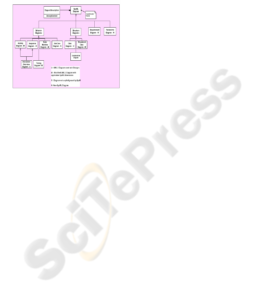
In order to visualize the relationship between the
UML and SysML languages, consider the diagram
shown in Figure 2.
Figure 2: SysML Diagram Taxonomy ,adapted from
www.sysml.org.
5 WHY SYSML?
The main question in this paper is, “why should
web-based application build and design Based on
SysML?” The Unified Modeling language (UML)
has, since its adoption in 1997, proved immensely
popular with software engineers to the point where it
is now the only widely used visual modeling
language for software engineering. In March 2003,
the OMG issued a Request for Proposal (RfP) for a
customized version of UML suitable for Systems
Engineering written by the SE DSIG(Object
Management Group 2003
) The customization of
UML for systems engineering is intended to support
modeling of a broad range of systems, which may
include hardware, software, data, personnel,
procedures, and facilities. There was only one
technology submission to the RfP, which was by the
SysML group, proposing a Systems Modeling
Language, SysML.
OMG (Object Management Group, 2005) states
“SysML supports the specification, analysis, design,
verification and validation of a broad range of
complex systems. These systems may include
hardware, software, information, processes,
personnel, and facilities.” Equally, INCOSE
(INCOSE, 2005) states that systems engineering is
an “interdisciplinary approach and means to enable
the realization of successful systems. It focuses on
defining customer needs and required functionality
early in the development cycle, documenting
requirements, then proceeding with design synthesis
and system validation while considering the
complete problem: Operations, Performance, Test,
Manufacturing, Cost and Schedule, Training and
Support, Disposal”.
REFERENCES
Athula Ginige , Proceedings of the 14th international
conference on Software engineering and knowledge
engineering SEKE '02
July 2002
INCOSE, 2005. What is Systems Engineering? Available
at: http://www.incose.org/ whatis.html
Jacobson I., Booch G., & Rumbaugh J. The Unified
Software Development Process(1999). Addison
Wesley.
Kruchten P. The Rational Unified Process: An
Introduction. Addison Wesley (1999).
Nora Koch and Andreas Kraus. The Expressive Power of
UML-based Web Engineering . 2nd International
Workshop on Web Oriented Software Technology
(
IWWOST 2002), Malaga Spain, June 2002.
OMG, “UML 2.0 Superstructure – Final Adopted
Specification”, OMG document ptc/03-08-02,
Available at:http://www.omg.org/
Object Management Group (OMG), 2003. Unified
Modeling Language: Superstructure version 2.0 Final
Adopted Specification ptc/03-08-02. [online] Available
from:
http://www.omg.org
Object Management Group (OMG), 2005, UMLTM for
Systems Modeling Language OMG, Available at
www.sysml.org
San Murugesan, Athula Ginige, Web Engineering:
Introduction and Perspectives , jois, Volume 2016 /
2001
SysML Partners 2003 , Systems Modeling Language:
SysML , Draft Specification v0.9, ,
www.sysml.org
Said Hadjerrouit, Web-based Application Development: A
Software Engineering Approach ,
ACM SIGCSE
Bulletin ,
Volume 33 , Issue 2 (June 2001), Pages: 31
- 34
Schneider G. & Winters J. Applying Use Cases: A
Practical Guide. Addison-Wesley. (1998) , Object
Technology Series
SysML Object Management Group (OMG), 2003,
UMLTM for Systems Engineering Request For
Proposal OMG Document: ad/03-03-41, Available at:
www.sysml.org.
Systems Modeling Language,OMG document number
ptc/2004-10-02 available at: www.omg.org
ICSOFT 2006 - INTERNATIONAL CONFERENCE ON SOFTWARE AND DATA TECHNOLOGIES
272
