
BPM: OVERALL ARCHITECTURE AND BUSINESS PROCESS
DESIGN TOOL
Anna Lisa Guido, Roberto Paiano
Dipartimento di Ingegneria dell’Innovazione-Università di Lecce, Via per Arnesano 73100 Lecce, Italy
Keywords: Business Process Management, Information System architecture, Business Process design tool.
Abstract: Business processes are playing in the last years a very important role in the companies and the explicit
introduction of them in the Information System architecture is a must. This requires the introduction of tools
and methodologies able to support both business and IT experts in process modelling, analysis and design
and to support cooperation between them. Our research work is focused not only on the overall Information
System architecture, but also on the tools that support the whole software development cycle from design to
development and maintenance. We start our research work from the business process design: we select a
notation able to cover the traditional semantic gap between business and IT experts and we provide a
powerful tool to support their job.
1 INTRODUCTION
Big efforts have done by companies to improve their
Information System (IS) that became, today, not
only a tool for activities automation but also a
powerful tool that supports managers in the
company’s analysis and to take timely decisions to
correct possible management errors that is to make
the IS more flexible in order to cover manager’s
requirements. To do this, companies abandoned the
vertical vision that locates business logic in
functional areas and orient them toward a transversal
vision that, according to the process logic, tries to
improve the management exploiting as much as
possible the existing resources. Process vision seems
a good way to guarantee to the manager a full
business activity control and to increase the
flexibility degree in the IS management in order to
apply immediately changes: a change to the process
must not implicate a re-implementation of the
applications but only a different way to manage the
existing business logic. The result must be, as BPM
(Business Process Management) idea state, a system
able to manage the daily flow of business process
providing analytical understanding of business
process that allows to take timely and coherent
decisions. Our effort focuses on the development of
tools and methodologies able both to understand and
to represent processes integrating them in the overall
IS architecture. The main effort, in our research
work, is to think to a methodology that allows to
design a Web Information System; the methodology
must address two different requirements such as to
take under control the web application design issues
(information, navigation and transactional aspects)
and to represent and to manage business activities
according to process logic. Close to the
methodology, we want to provide a set of tools that
help in the transition from the process representation
to the final web application. BPM tools and
methodologies are oriented both to business experts
and to IT experts: business experts are interested to
define, analyze and optimize processes while IT
experts must understand business requirements and
develop (or adapt) applications in a rapid and
efficient way to meet business user requirements. It
is important to cover the traditional semantic gap
between IT and business experts (Dieter, 2004). This
is an hard task because business and IT competences
and goals are different but we want to provide the
same tool and it must be simple and efficient for two
different kinds of users with different requirements.
375
Lisa Guido A. and Paiano R. (2006).
BPM: OVERALL ARCHITECTURE AND BUSINESS PROCESS DESIGN TOOL.
In Proceedings of WEBIST 2006 - Second International Conference on Web Information Systems and Technologies - Internet Technology / Web
Interface and Applications, pages 375-380
DOI: 10.5220/0001258603750380
Copyright
c
SciTePress
2 BACKGROUND
Since ‘90s, process logic began to affirm through the
BPR theory (Business process Reengineering)
(Hammer, 1990) that introduced the process as the
way to improve the company’s management.
A first step towards BPM idea was the workflow
idea (proposed and supported by Workflow
management coalition (http://www.wfmc.org)) but
there are two key differences with BPM idea:
• Processes automated by workflow focus on a
single department of the company: BPM,
instead, allow to have a horizontal view
managing processes that involves all company’s
department. This makes more scalable and more
useful BPM than workflow.
• Processes taken into consideration from
workflow are processes where only people
performed process steps while BPM manages
process where steps are performed both by
people and systems.
Today, process logic is hidden in the application
level and, often, the way that this is made is in the
mind of the companies IT experts and it is not well
documented. The IS obtained is very hard to
maintain. A change to the process logic needs a
revision of the business logic with long times and
high costs. The processes are not explicit , so it is
very difficult to monitor and manage them. The next
step after workflow was the introduction of BPM
suites that try to make explicit the process definition
and management. A recent study (Miers, Harmon,
2005) compares different BPM suites from different
point of view such as cost, platform, User Interface
etc. As an example, Filenet P8
(http://www.filenet.com) allows to represent
processes and to manage their execution; Filenet P8
provides administration tools to manage processes
and user involved in the system. It focuses on
document management and provides a web
application (named Workplace) where actors can
load their task and work with it. Workplace allows
single user to view and work with processes in a
web application but each user access to only one
page and so the Web Application paradigm is not
taken into consideration. There are other suites like
Filenet P8 such as W4, iLog, PopkinSoftware,
Fuego(http://www.Fuego.com,http://www.ilog.com,
http://www.popkin.com, http://www.w4global.com).
The main issues that we can see in these suites are:
• High cost: suites are difficult to apply in small-
to-medium size companies because; they
require high investments both to purchase
hardware and to improve the skills of people in
the company ;
• Ad hoc notation to represents process often hard
to read and to understand both from business
experts and from IT experts;
• Lack of methodology that helps in the transition
from process design to the final web
application.
Our efforts are oriented to solve these open issues
developing tools and methodologies easy to be
acquired and applied both by IT and business user.
3 ARCHITECTURE AND TOOLS
FOR PROCESS-ORIENTED
WEB INFORMATION
SYSTEMS
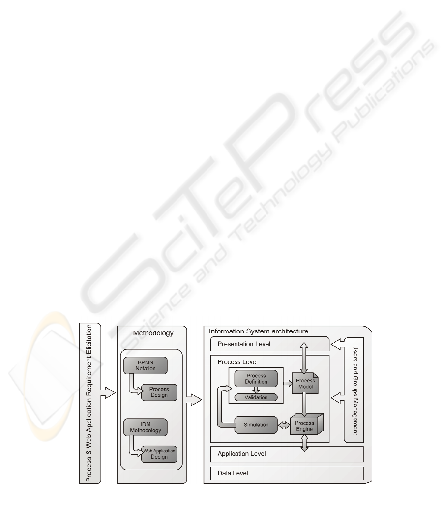
The architecture that we propose in our research
work is showed in Fig. 1 and it is made up of
Figure 1: The architecture of our research work.
WEBIST 2006 - WEB INTERFACES AND APPLICATIONS
376
requirement analysis, methodology and the four-
level IS architecture. Requirement elicitation phase
is the input for Web Information System design
methodology that is oriented to integrate in an
opportune way the IDM (Perrone, Bolchini, Paolini,
2005) design methodology (that solves information,
navigation and transactional problems typical of web
applications) with process definition. Methodology
is the starting point to obtain the final Web
Application that goes over the simple definition of
information contents and navigation between them
but includes also a process. The introduction of
process level is the main effort in our architecture
and has two goals:
• Business experts focus on the processes and
manage directly them to modify the company
work: a change to the process will directly
reflect on the application that implements this
process without a full re-design and/or re-
implementation; to change process means to
change the management of the business logic
and not the business logic itself;
• From the IT experts point of view the code
maintenance is simplified: a change in the
business logic means a change in the application
level code without any (or with few) changes in
the Presentation and Process level; a change in
the process will be directly made in the process
level without modify the business logic and
with some changes in presentation level.
Process definition, followed by process
validation, allows business experts to obtain the
process model: a formal representation of the
process where it is possible to find all the
information about the process. Process model is the
input for the process engine where process instance
are managed. The process engine interacts with the
application level and allows to include in the process
management also business logic yet implemented in
the company. Finally, the process simulation block
that allows to define Key Performance Indicator
(KPI) and to verify if the process meets the
performance requirements. Simulation phases should
require the re-definition of the process to obtain the
performance required.
4 NOTATION CHOISE: BPMN
We focus on the process level and our first step is
the design and implementation of the business
process editor that support both the business experts’
work (understand and design process) and the IT
experts work (understands requirements and
implements the application). We know that there are
on the market several business process editor but
they are expensive and many of them does not
support BPMN notation. Moreover, we observe that
there is not a standard language machine readable to
represent process design but, in our overall
architecture the process model in a machine readable
format is a must. Therefore, we choose an
ontological language to represent process design and
in our business process it is supported the export
from the graphical design to the machine readable
ontological language. The business process notation
to adopt must be simple, easy to use and to
understand both by business experts and by IT
experts: it must cover the semantic gap between
business and IT experts.
There are different notations to represent
business process. UML (OMG, 2003) activity
diagram, for example, allows to define process but it
is not simple to understand; another example is the
traditional workflow representation that is not
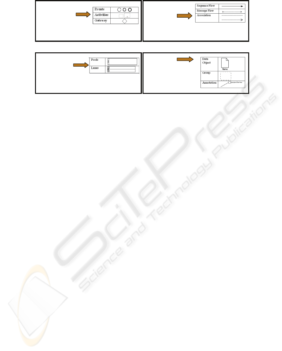
Flow Object
Connecting
Objects
Swimlanes
Artifact
Defines how business process works
Are useful to connect each other flow object or flow
object and other BPMN elements
Are useful to represents actors (or
group of actors) involved in the
process
Useful to document the
process design gives
additional information to the
process definition
Figure 2: BPMN Core object.
BPM: OVERALL ARCHITECTURE AND BUSINESS PROCESS DESIGN TOOL
377

intuitive and allows to define only the process flow
without take into consideration human and/or system
interaction.
Exploring different notations, our choice is on a
recent notation: BPMN (Business Process
Management notation) (Stephen A., 2004) proposed
by BPMI (Business Process Management Initiative)
that, thanks to its readability and completeness
seems the best way to represent a process. The main
BPMN goal is to cover the semantic gap between IT
and Business experts. BPMN, today, is not a
standard but several companies support it. The
design obtained is clear and it is easy to understand
the actors (human or system) involved in the process
and the relationships between them. BPMN notation
is made up of two different details level:
• core objects made up of base elements that
allow to define a process in the large;
• details may be provided adding properties to
obtain a detail level close to the detail needed in
the implementation phase.
These different details level makes the design
easy to understand not only by experts of the
notation but also by not experts. At the same time,
BPMN allows to provide in the design phase all the
details needed for implementation phase. Core
Objects are made up of four different groups of
primitives (fig.2): each group is made up of different
elements and for each element, there are different
variants. BPMN defines also the context where each
element may be used. As an example, it is not
“legal” the use of Sequence Flow between Lane and
it is imposed to use Message Flow. Starting from
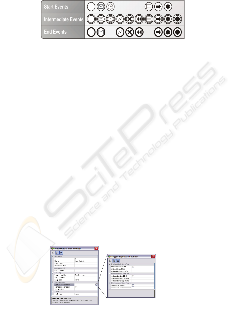
core object it is possible to define another detail
level. As an example, there are different types of
Start event depending on the context where it is
used; each type of start event has its own icon inside
of the general start event icon.
5 PROCESS DEFINITION: A
BPMN PROCESS EDITOR
A look to the business process design tools market
brought us about an important consideration: the
only free way to design a process using BPMN
notation is the use of Visio palette
(
http://www.workflowresearch.de/Downloads/BPMN) but
this design is far from an integrate environment. In
this context, we developed a design tool for process
definition with several goals:
• To hide to the user the notation complexity and
to support the user in the choose of the right
BPMN element in the right context (useful for
business experts);
• To support BPMN notation in all its complexity
(useful for IT experts);
• To export the process design in a machine
readable format (we choose OWL (W3C, 2004)
an ontological language machine readable);
• To provide the same tool to two different type
of user: business experts and IT experts.
• The BPMN editor must be accessible on the
web.
To reach these goals, we started our research
work with the design and implementation of a
BPMN editor. Our effort is oriented to hide to the
final user the complexity of the notation due to the
several primitives and their properties.
The editor, never show all BPMN elements to
the user but drives the user in the choice of the
correct elements in the correct context.
To understand this, in fig. 3 we can see an
overview of possible type of “Events” and related
icons that will be used inside (the same is for other
BPMN elements). Our effort in the design and
implementation of BPMN editor has been oriented
to support user design: the right stereotype depends
on the user action. For example, if the user chooses
an event from the palette (the palette shows only a
circle without start, intermediate or end distinction)
it became automatically a Start Event without any
icon inside. If the Event becomes a target for a
sequence flow and the same Event is a source for
another sequence flow it automatically became an
Intermediate Event (without icon inside). In the
same way if the Event is target for a sequence flow
and it is not a source for any other sequence flow, it
became End Event (without icon inside). Another
feature of the BPMN editor is the support to the
design of the flow. BPMN defines connecting rules
both for Sequence Flow and for Message Flow. User
without experience on BPMN has some problems to
know what kind of connection is legal between two
BPMN elements. To solve this problem our editor
provides only the right interconnection tool:
depending on the context and on the connecting
rules the editor automatically provide the correct
connection. As it regards properties of each BPMN
element, our efforts has been oriented to provide the
user with the capability to insert a property, using a
property form, by the right click of mouse on the
BPMN element icon. In this way, the work area is
only for the process design.
This is an innovative idea because tools on the
market only present all the properties in a single
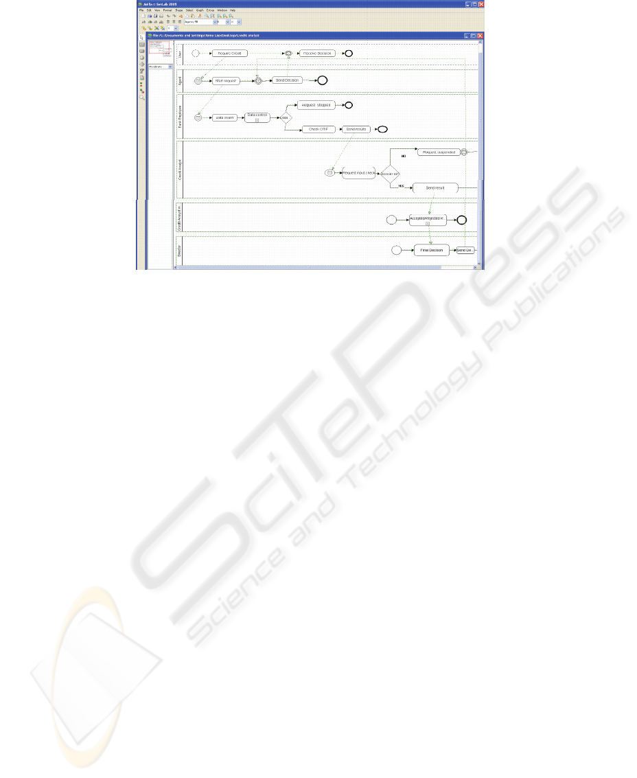
form and the user may be disoriented. In fig.4,we
WEBIST 2006 - WEB INTERFACES AND APPLICATIONS
378
can see the property form related to the BPMN
Activity: all the properties are editable (through a
text box) and, for each property, there is a short
description of its use.
For complex property (as “Type of Sub-Process”
in fig. 4) there is another property form strictly
connected with the first.
The editor allows business user to reach the
detail level necessary to achieve its goal; at the same
time IT experts may read in the first step all the
process design and then read all process details in
the property form. Some details unknown to the
business user (as an example implementation
details) may be added from the IT experts in the
same business process design where business
experts work.
Our business process editor allows to see, thanks
to the BPMN notation, all actors (human and/or
system) involved in the process and the overall flow.
An OWL machine-readable representation of the
business process model may be obtained thanks to
the export function.
5.1 BPMN Editor Architecture
The BPMN editor developed in this research work is
delivered on the web. This choice requires an effort
in the design and implementation phase and the
necessity to provide a rich client with several
functionalities and with graphic tool.
The tool designed and implemented is a three-
tier application, made up of
• Client Tier: a rich client where the user works.
• Web Tier: where the servlet container allows to
implements web services.
• Ontology Tier: the infrastructure to manage the
ontological metamodel that allows to export the
business process model in an OWL format.
The introduction of BPMN notation in a
graphical web application tool requires to provide a
real short time response to each user operation so it
is necessary to have a final web application of small
dimension. On the client-side there is an applet
implementing the editor graphical aspect. To have
low download time the ontological metamodel is on
the server because to manage the ontology
metamodel we use very large software containers.
Web services provide the communications between
the client side and the ontological metamodel. The
architecture of the editor is a client-side architecture
where the client-side manages the user interaction
and the graphical aspects (icons and property) while
server-side manages the ontological metamodel.
5.2 BPMN Editor: A Case Study
To understand the functionality of the Business
process editor, we use it to model the business
process “personal credit” (with several actors and
several tasks) for a local bank. (Fig. 5) We can see
the “User” who require, through an Agent, a
personal credit, the “bank employee” that makes a
few control activity, the “Credit Analyst” that
provides the first evaluation to the request, the
Figure 3: Different type of event.
Figure 4: Property Form and sub-property form.
BPM: OVERALL ARCHITECTURE AND BUSINESS PROCESS DESIGN TOOL
379
“Credit analyst manager” that provides its own
evaluation, finally the “Director“ who provides the
final evaluation but only in a few special case. The
process designer, with our editor, can define,
thought the toolbar, one pool for each actor involved
and, for each pool, can define its own property (by
right click). The business process editor provides a
toolbar where it is possible to select the event, the
activities and gateways. Selecting one of them,
depending on the context, the correct icon is inserted
in the design. The design obtained with this editor
has been obtained in a few hours (the previous
analysis of the process has been made first) by
people not expert in BPMN notation.
6 CONCLUSION & FUTURE
WORKS
Modern IS will be more flexible and able to answer
“on the fly” to the manager innovation requirements;
this is taken by explicit introduction of process level
in Web Information System architecture. The only
process analysis and re-definition is not too much to
meet the IS flexibility and, as consequence, it is
necessary to integrate the process in the IS
architecture making explicit the management of it.
Our research work aims to introduce process level in
the overall IS architecture. This paper focus on the
first step of our work that is on the development of
the Business Process editor according to the BPMN
notation. The editor, delivered on the web, simplifies
the designer work thanks to the possibility to interact
only with core objects of the BPMN notation that
adapt themselves depending on the design context.
In this way, the final design will not contain errors
due to the notation misunderstanding. Our next step
is the definition of a methodology that allows
obtaining a final web application starting from
Process design.
REFERENCES
Derek Miers, Paul Harmon (2005) “The 2005 BPM suite
report Version 1.0”,Retrieved March 15, 2005, from
http://www.bptrends.com
Dieter E.Jenz President Jenz & Partner GmbH (2003)
“Ontology-Based Business Process Management The
Vision Statement”, retrieved September, 2004, from
http://www.jenzundpartner.de/Resources/
Hammer M. (1990), “Reengineering Work: Don’t
Automate, Obliterate”.Harward Business Review, 68,
pp.104-112
OMG (September, 8 2003) “UML 2.0 Superstructure
Specification” (version 2.0)
Stephen A. White for BPMI and IBM Corporation (May 3,
2004): “Business Process Modeling Notation
(BPMN)” (Version 1.0 ), Retrieved May, 2004, from
www.bpmn.org
Vito Perrone, Davide Bolchini, Paolo Paolini; (2005) “A
stakeholders centered approach for conceptual
modeling of communication-intensive applications”,
Proceedings of the 23rd annual international
conference on Design of communication: documenting
& designing for pervasive information pp: 25 – 33,
ISBN:1-59593-175-9
W3C (February, 10 2004) “OWL Web Ontology language
Reference” W3C Recommendation.
Figure 5: Part of Credit Analyst case study designed with BPMN Editor.
WEBIST 2006 - WEB INTERFACES AND APPLICATIONS
380
