
GENERATING TEST CASES FROM SEQUENCES OF USE
CASES
Javier J. Gutiérrez, María J. Escalona, Manuel Mejías, Jesús Torres
Department of Computer Languages and Systems. University of Seville. Spain
Keywords: System testing, automatic generation of test cases, use case.
Abstract: An important task in a development process is to test that functionality of the system under development
satisfied its requirements. Test cases have to verify real behaviour of the system when it will in production.
This paper shows a systematic approach to generate test cases that exercises several sequences of use cases
over web applications.
1 INTRODUCTION
Software testing can be performed at several levels.
This paper is focused in system testing level. System
test cases are mainly obtained from functional
requirements of system under test (Bertolino 04). It
is possible to derive test cases in a systematic way
from functional requirements. Nowadays, there are
several approaches to drive the derivation process
from requirement to test cases. A list of references
can be found in (Denger 03) and (Gutierrez 04),
(Gutierrez 05). However, many approaches to
derive functional system test cases are focused over
functional requirements in isolation and do not
studies web applications (Gutierrez 05). These
approaches can derive a set of test cases for every
functional requirement but does not considerate
dependences among several requirements. An
example of derivation of test cases from each use
case of a web application can be found in (Gutierrez
05(2)). Main contributions of this paper are: first,
introducing an approach to derive sequences of use
cases; second, showing a practical case over a
simple but not trivial web system.
2 GENERATION OF TEST CASES
Main goal is to derive valid sequences of use cases
to be implemented as test cases.
Our approach is composed of 6 activities described
in points below.
2.1 Identify Use Case Variables
The idea of use case variable is similar to
operational variables defined in the Extended Use
Case Test pattern (Binder 00). We define a use case
variable as a piece of information that a use case
needs to perform its task. Use case variables are
classified into three groups listed in table 1. More
groups can be added if needed.
Table 1: Types of use case variables.
Gro
up
Description
Inner The variable stores information that the use
case needs. That information does not depends
on any other use case.
In The variable stores information that the use
case must receive from another use case.
Out The variable stores information that other use
cases needs.
Generally, in and out variables are included in
the precondition and post condition of a use case
(Nebut 03). Inner variables can be identified
studying all scenarios defined into a use case. We
have also to identify the domain for every variable.
Complex domains can be described with store
requirements, defined in (Escalona 04), or with class
diagrams (Labiche 02).
Use case variables help to identify and define the
precedence of use cases. Inner variables are not
relevant in sequences derivation process. However,
at the time to implement test cases, we have to
assign values to all variables, even inner variables.
473
J. Gutiérrez J., J. Escalona M., Mejías M. and Torres J. (2006).
GENERATING TEST CASES FROM SEQUENCES OF USE CASES.
In Proceedings of WEBIST 2006 - Second International Conference on Web Information Systems and Technologies - Internet Technology / Web
Interface and Applications, pages 473-476
DOI: 10.5220/0001245804730476
Copyright
c
SciTePress

2.2 Build Behavioural Model
Behavioural model is composed by one or several
UML activity diagrams for each actor that interacts
with the system. Every activity diagram has only the
use cases accessible to that actor. Steps to build an
activity diagram from use cases are enumerated in
table 2.
Table 2: Steps to build a behavioural model.
Step
1 Identify start and end points.
2 Draw an activity for every use case. In and out
variables are added into the name of the activity.
3 If use case B can only be executed after executing
use case A, a transition among activity A and B is
added.
4 Annotate the diagram with preconditions, post
conditions and invariants.
A behavioural model is not a navigation model.
Navigation models describe the pages and
information and how a user might navigate among
them. However, behavioural model describe the
functionality that a user might exercise.
2.3 Identify Loops
A loop is a sequence of use cases that might be
executed a number of times, or infinite. Loops are
very common in behaviour models described in
point before. For example, when introducing data,
the system validate that information and, if there are
errors, asks for correct invalid values several times.
Table 3: Notation for canonical path.
Notation Description
A -> B Use case B can only be executed after use case
A is executed.
A -> {B |
C}
After execution of use case A, sequence B of
use cases or sequence C of use cases might be
executed, but not both at same time. Selection
can involved more than two sequences.
(A)b Sequence A of use cases is executed b times.
To manage loops, we assign a variable to every
loop. That loop variable will have a range of values
that indicates the number of times that the loop can
be repeated. The way to obtain the values (the times
a loop is traverse) are: the functional specification
indicates the number of times, deductible from the
working environment or final user experience.
2.4 Derive Canonical Paths
A canonical path is an expression that describes a set
of possible paths over a behaviour model. Notation
for canonical path is similar to regular expressions
and it is described in table 3.
2.5 GenerateSequence of Uses Cases
Sequences of use cases are generated from canonical
paths. A sequence of use cases is a path through the
behavioural model that begins in the start point,
finish in the end point, and has concrete values to all
variables implied. There are several criteria to
generate sequences from canonical paths. Criterion
selected in our approach is all use cases criterion.
All use cases must be covered in, at least, one path.
We propose two different criteria to determine the
number of repetitions of loops. First criterion is to
select a random number for each loop variable in
every path that traverse the loop. Second criterion is
to generate a different path for each value in the
range of loop variable. We propose the same criteria
used in loops to determine a concrete sequence from
a selection.
2.6 Identify Conditions Over Test
Values
Some sequences of use cases can be only executed if
variables have concrete values. Those conditions are
identified and expressed as boolean conditions or
OCL expressions. Test values generated for each
sequence must satisfied all conditions associate to
that sequence.
3 CASE STUDY
System under test is a simplified version of a web
application to manage a link catalogue on-line.
Figure 1: Use case diagram.
Use cases of user actor are showed in figure 1
and described in tables from 4 to 6. Use cases
“search link by category” and “Search recent link”
have been omitted due it is similar to other uses
cases.
WEBIST 2006 - WEB INTERFACES AND APPLICATIONS
474
.
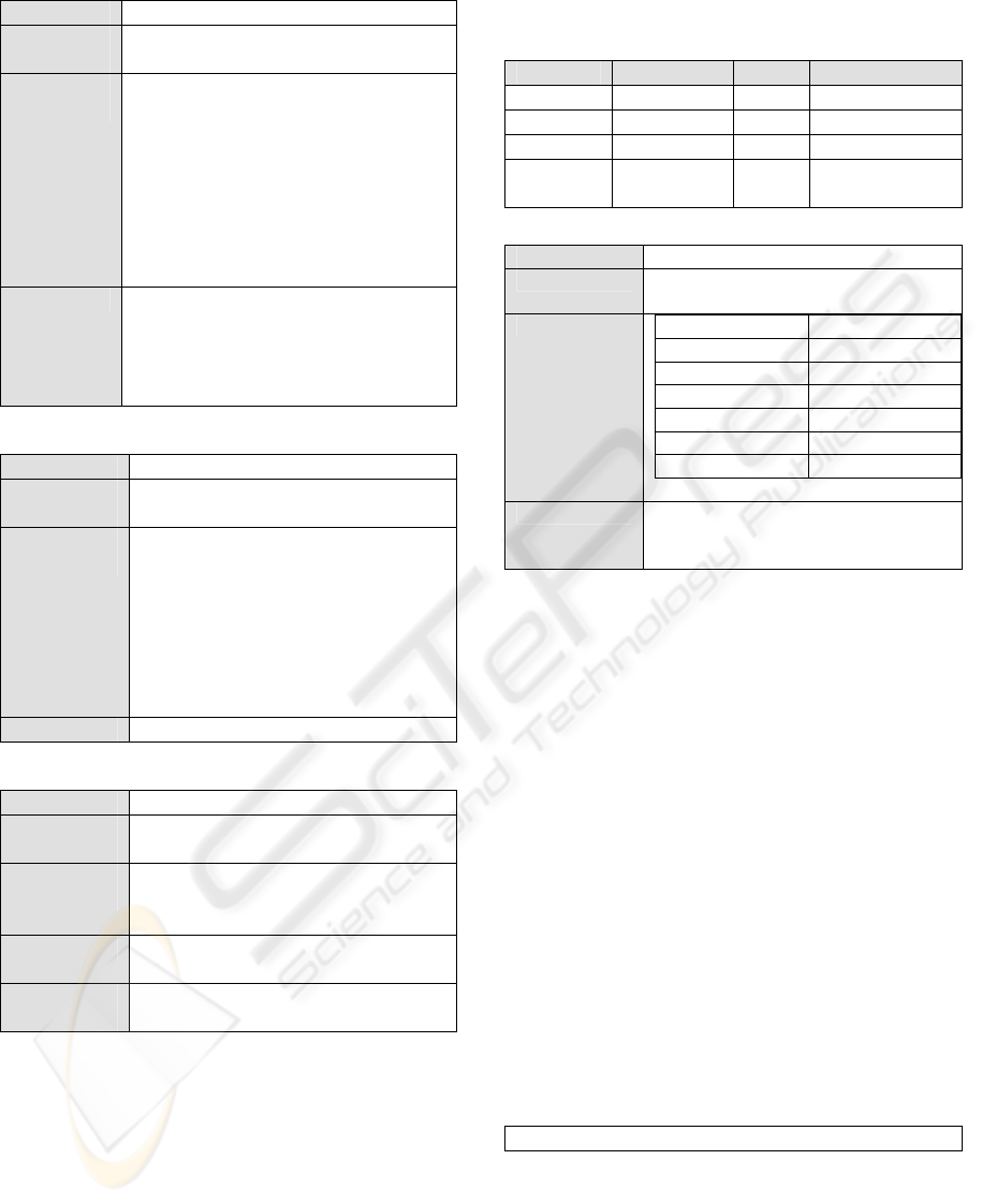
Table 4: Use case “add new link”.
Name UC-01. Add new link
Preconditio
n
No
Main
sequence
1. System select “top” category and
shows the form to introduce the
information of a link (SR-02).
2. If the user selects a different
category, system changes the category
and shows the form again.
3. User introduces information of the
new link and press insert button.
4. System stores the new link.
Errors 2. At any time, user can press cancel
button and exit of the form.
4. If link name or link URL is empty,
system shows an error message and ask
the information again
Table 5: Use case “search link by description”.
Name UC-02. Search link by description
Preconditio
n
No
Main
sequence
1. System shows a form to introduce
the description.
2. User writes the description and press
search button.
3. System searches all links with
description that coincides with
description of the user and executes
UC-05.
Errors No.
Table 6: Use case “show results”.
Name UC-05. Show results
Preconditio
n
A search have been made
Main
sequence
1. System shows a table with
all information about the
links found (SR-02).
Errors 1. If search returns empty values,
system show a “no links” message
Post
condition
No.
First activity is to identify variables of use cases.
Use case 01 needs information about the new link to
add, however, there are no other use cases that
depends of the new link. Thus, new link is an inner
variable. Use case 05 needs the results to show.
Those results are provided by use case 02 or 03 or
04. Thus, one of those use cases must be executed
before execution of use case 05.
Domain, in table 7, references to a store
requirement which define the information that
system manages for each link. Table 8 shows the
store requirement. A description in depth of store
requirements and their templates can be found in
(Escalona 04).
Table 7: Use case variables.
UC Name Type Domain
UC-01 New link Inner SR-01
UC-01, 04 Category Inner String
UC-02 Description Inner String
UC-02,
03, 04, 05
Result Out Array of SR-01
Table 8: Store requirement.
Name
SR-01. Link.
Use cases
UC-01, UC-02, UC-03, UC-04, UC-
05
Specific data
Name Domain
Identifier Integer
Name String
Category Integer
URL String
Description String
Date Date and time
Restrictions
Identifier must be unique.
Parent category must be an exiting
category.
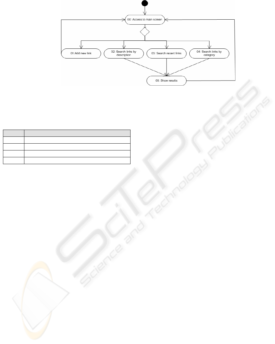
Second activity is to build the behaviour model.
Variables in table 7 allow identifying the precedence
of each use case. Start and end points are easy to
identify due there is one use case to begin and
another one to exit the system. Behaviour model
from use cases has been building using steps
described in point 2.3 and is showed in figure 2. A
new use case has been added in figure 4. This use
case is executed when user access to the system and
shows a GUI to execute use cases from 01 to 04.
Next, we identify loops and assign a loop
variable to each one. Model in figure 4 has only one
loop, which represent several operations that a user
performs over the system. This loop has a variable
called “loop”. It range is from 1 to infinite.
However, it is impossible and unrealistic to test
infinite operations, so we set the variable in a range
from 1 to 4 operations.
Next activity is the derivation of canonical paths.
Due the simplicity of the system, only one canonical
path is enough to cover all possible paths. The
canonical path is showed in table 9.
Table 9: Canonical path.
(UC-00->{UC-01|{UC-02|UC-03|UC-04}->UC-05} )
loop
In activity 5, the canonical paths are instantiated
to generate sequences of use cases. Concrete values
to each variable and loop are assigned to each path
and a concrete use case is chosen in every selections.
We generate a different path for every different
value in the range of a loop variable. We also
generate a different path for every possible option in
GENERATING TEST CASES FROM SEQUENCES OF USE CASES
475
a selection. The number of possible paths is 20.
Examples are listed in table 10.
Table 10: Paths example.
Id Loop = 1
1 00 -> 01-> 00
2 00 -> 02 -> 05 -> 00
3 00 -> 03 -> 05 -> 00
4 00 -> 04 -> 05 -> 00
Finally, conditions over test values to traverse
concrete paths are identified. However, in this
practical case, there is not any variable that have to
get a concrete value to execute any of the path
obtained. Test values that satisfied conditions have
to be generated for each variable to implement test
cases. This one can be done applying specific
techniques like Category-Partition method (Ostrand
88) or boundary values technique, or capturing real
data from user sessions (Elbaum 05).
4 CONCLUSIONS
Deriving sequence of use cases is a valuable
technique to build realistic system test cases. This
process do not need that system under test is build
(due it is based on its functional specification, nor in
code), so it might begin at early phases of
development process, avoiding the lack of time to
testing and allowing the detection of faults,
ambiguities and inconsistencies in requirements. The
best improvement is obtained combining sequence
of use cases with test cases derived for each use
case. This one allows to test a sequence of different
scenarios instead be limited for main scenario. This
approach can be applied in addition to other
approaches focused in deriving test cases from use
cases in isolation like (Ruder 04).
REFERENCES
Bertolino, A., Gnesi, S. 2004. PLUTO: A Test
Methodology for Product Families. Lecture Notes in
Computer Science. Springer-Verlag Heidelberg. 3014
/ 2004. pp 181-197.
Binder R.V. 2000. Testing Object-Oriented Systems.
Addison-Wesley. USA.
Denger C., Medina M. 2003. Test Case Derived from
Requirement Specifications. Fraunhofer IESE Report.
Elbaum S., et-al. 2005. Leveraging User Session Data to
Support Web Application Testing. Inner Report.
Department of computer Science and Engineering.
University of Nebraska. USA.
Escalona M.J. 2004. Modelos y técnicas para la
especificación y el análisis de la Navegación en
Sistemas Software. Ph. European Thesis. University of
Seville. Spain.
Gutierrez J.J., Escalona M.J., Mejías M., Torres J.,
Álvarez J.A. 2004. Comparative Analysis of
Methodological Proposes to Systematic Generation of
System Test Cases from System Requirements. SV05.
pp. 151-160. Paris, France.
Gutierrez J. 2005. Gutiérrez, J.J., Escalona M.J., Mejías
M., Torres, J. 2005. Analysis of Proposals to Generate
System Test Cases From System Requirements.
CAiSE’05 Forum. Porto. Portugal.
Gutiérrez J.J., Escalona M.J., Mejías M., Torres J. 2005
(2). A practical approach of Web System Testing.
Advances in Information Systems Development. pp.
659-680. Ed. Springer Verlag Sweeden. August.
Labiche Y., Briand, L.C. 2002. A UML-Based Approach
to System Testing, Journal of Software and Systems
Modelling (SoSyM) Vol. 1 No.1 pp. 10-42.
Nebut, C. F., et-al. 2003. Requirements by contract allow
automated system testing. Proceedings of the 14th
International Symposium of Software Reliability
Engineering (ISSRE'03). Denver, Colorado. USA.
Ostrand, T.J, Balcer, M.J. 1988. Category-Partition
Method. Communications of the ACM. 676-686.
Ruder A. et-al. 2004. A Model-based Approach to
Improve System Testing of Interactive Applications.
ISSTA’04. Boston, USA.
Figure 2: Behaviour model.
WEBIST 2006 - WEB INTERFACES AND APPLICATIONS
476
