
Combining Neural Tracking and Control to Improve
Rehabilitation of Upper Limb Movements in Hemiplegia
M. Goffredo, I. Bernabucci, M. Schmid, S. Conforto and T. D’Alessio
Department of Applied Electronics
University ROMA TRE
Via della Vasca Navale 84, I-00146 Roma Italy
Abstract. This paper aims at introducing a novel approach for assisting and re-
storing upper arm movements in stroke patients. The presented system inte-
grates advanced markerless motion analysis together with an artificial neural
network controller for a biomechanical arm model. The keypoint of the project
is to acquire kinematics information from the healthy arm of a stroke patient
during planar arm movements and elaborate them in order to obtain a self-
rehabilitative stimulation of the plegic arm of the same patient. The first ex-
perimental tests show good results and allow to define working direction for the
extension of the work and for its application in clinical contexts.
1 Introduction
Rehabilitative practice in stroke patients has strengthened its empirical foundation on
the basis of the recent advances in neuroscience methods, which led to deeper under-
standing of motor control and learning mechanisms [1]. Among them, long-term
potentiation (i.e. synapses are able to encode new information to represent a move-
ment skill) has been considered to play a relevant role in restoring functions. A criti-
cal element for the success of these mechanisms resides in the repetition of inputs for
the motor cortex, which serves as a biological teacher for the neurons acquiring novel
skills. This process could easily be implemented through experience and training,
which induce physiological and morphological plasticity, by strengthening synaptic
connections between neurons encoding more common functions [2]. In this context,
the key concept behind rehabilitation is, from a neural network point of view, the
repetition of movements in a learning-by-examples paradigm: by repeating move-
ments in either passive or assisted way, the brain is exposed to different examples,
and its neurons adapt their connections to the newly presented conditions. In this
general context, the Functional Electrical Stimulation (FES) could heavily enhance its
role in rehabilitation, since it can be considered as an artificial teacher that allows
exploration of the workspace, thus representing a driver for different examples: fol-
lowing this perspective, FES has broken the walls of simple functional substitution
[3] to come up to the requirements of rehabilitation, and has been proven as success-
ful both in lower [4] and in upper limb movements [5]. These encouraging findings
Goffredo M., Bernabucci I., Schmid M., Conforto S. and D’Alessio T. (2006).
Combining Neural Tracking and Control to Improve Rehabilitation of Upper Limb Movements in Hemiplegia.
In Proceedings of the 2nd International Workshop on Biosignal Processing and Classification, pages 96-105
DOI: 10.5220/0001224400960105
Copyright
c
SciTePress
recently brought to the development of FES-assisted rehabilitation programs in hemi-
plegic patients [6]. Some of the limitations driven by FES in rehabilitation programs
reside both in the rather raw and un-physiological control of the stimulation, and in
the invasiveness of the approach. While for the latter issue, advancements in technol-
ogy made it possible to obtain efficient non-invasive stimulators (see e.g. Handmaster
[7] and the Bionic Glove [8]), the issue of biological plausibility of stimulation wave-
forms has not yet been deeply investigated, though some pioneering work has been
found in literature [9]. The resolution of the inverse dynamics, i.e. extracting the
muscular forces needed to obtain a specific movement from a starting point to a de-
sired endpoint is one of the problems to be solved to efficiently drive the stimulation:
to this end, artificial neural networks have been hypothesized as biologically plausible
controllers [10], and then shown as efficient in the resolution of the problem [11].
Moreover, if a stand alone system has to be used for an effective self-rehabilitation
exercise, one point to be addressed resides in the information regarding starting posi-
tion and desired endpoint to be provided to the controller. Among the possible sen-
sors that can efficiently gather these data, one can cite goniometers and motion cap-
ture systems, being the latter less invasive if no markers are to be applied on the body
surface.
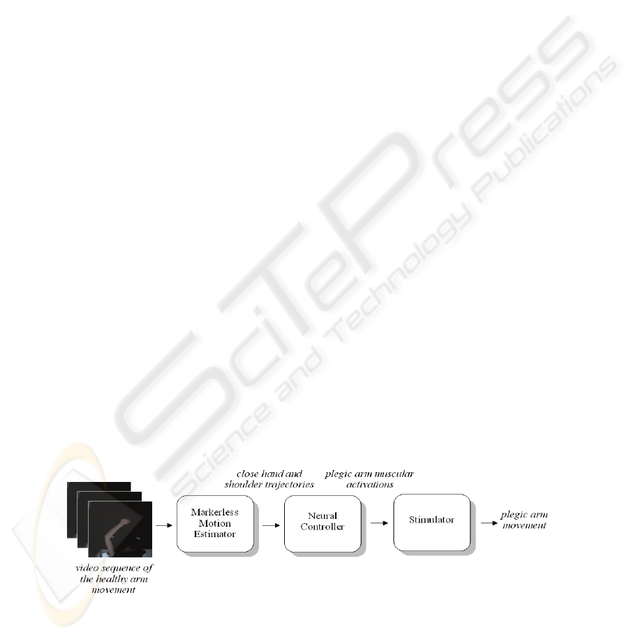
Following this perspective, the aim of the current work is to provide a general frame-
work for the integration of three blocks that could constitute a stand-alone self-
rehabilitation system: a motion tracking system for the estimation of the desired tra-
jectory obtained from movement of the sound arm, relying on silhouette tracking
through a novel markerless motion estimation method; a neural controller for the
resolution of the inverse dynamics to obtain the desired stimulation; the stimulator
block, that serves as effector to drive the plegic arm. The FES is driven by the inte-
gration between a markerless system for tracking movement and a neural network for
controlling the muscular stimulations. The overall system to be realised has been
named TwinN-FES (Tracking with neural Network-FES). In particular, this work
will deal with the first two blocks of the system.
2 Methods
Figure 1 shows a non formal flow diagram of the proposed method, while in the fol-
lowing subparagraphs the first two blocks are described in detail.
Fig. 1. The proposed method.
97
2.1 The Markerless Motion Estimation Method
The markerless motion estimation method, proposed to track the upper limb during
the execution of planar movements, aims at estimating the movement of the entire
arm. The high deformability of human silhouette and consequently the unacceptabil-
ity of a rigid body approximation are critical problems in markerless motion analysis
[12], [13], [14]. In this context, energy-minimising deformable models offer a partial
solution. The widely used Active Contour Model, called Snake, is driven by a cost
function generated by processing an image. The Snakes [15] are widely used in litera-
ture for segmentation and contour detection but they are not applied to track silhou-
ettes subtly changing their shapes during the movement. For this reason they are not
successfully applicable for human tracking.
This paper introduces a new deformable model for contour tracing that allows to track
a deformable silhouette, i.e. the upper limb movement. The method is based on a
closed Snake predicted by an Artificial Neural Network (ANN) and then called Neu-
ral Snake. The neural approach is based on a multilayer Perceptron (2 hidden layers
with 15 neurons each) trained for snake configuration prediction. The horizontal and
vertical components of position, velocity and acceleration of each contour point in the
current frame are the ANN inputs (number points x 6), while the output is constituted
by the horizontal and vertical components of the position of each contour point in the
subsequent frame (number points x 2). The training set is obtained by analysing sev-
eral ad-hoc video sequences: they are characterised by slow upper limb planar move-
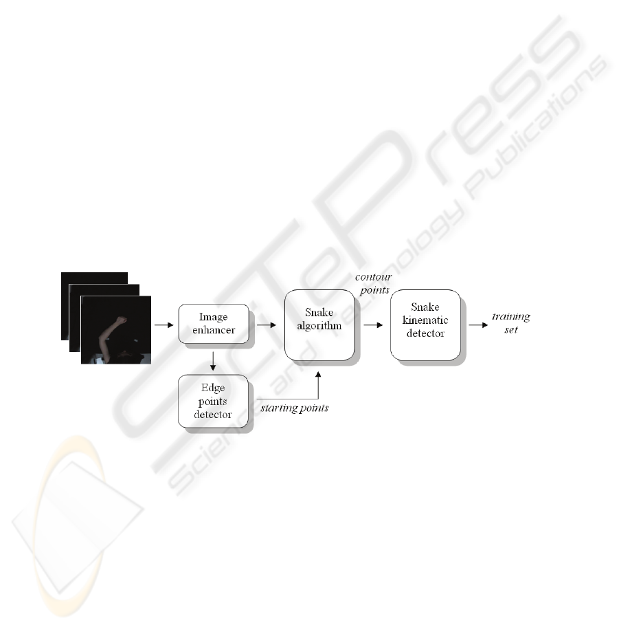
ments with high frame rate on a dark background. Figure 2 shows a flow diagram of
the proposed algorithm which extracts the training set from a video sequence.
Fig. 2. Graphical representation of the proposed algorithm for the training set achievement.
The frames of the video sequences are analysed first by the image enhancer and edge
detector block in order to determine the upper limb edge over time (figure 3). At first
the input RGB sequence is converted to greyscale, then the distribution of its histo-
gram is modified by using the VirtualDub program [16]. In particular, the contrast
filter (200%) and the sharper filter (maximum) are used. After filtering the image by a
two-dimensional median filter (5-by-5 filter window), the arm silhouette is extracted
with an edge detection procedure, as reported in Canny [17]. The upper limb edge is
then uniformly sub-sampled by choosing an Euclidean distance between consecutive
98
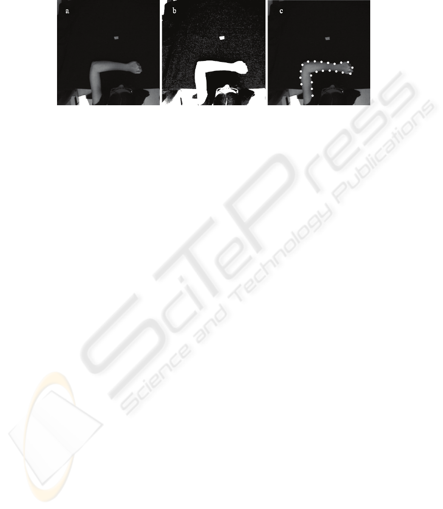
points. The sub-sampling procedure aims at keeping constant over time the number of
edge-points (i.e. in figure 3 the number of points is 22).
Fig. 3. 66
th
frame of one of the video sequences used for training the ANN. a) Original frame.
b) Frame after the application of the image enhancer. c) Points obtained after the sub-sampled
edge detector.
The edge-points are then used as starting points for the Snake algorithm as reported in
Kass [15]. Then the obtained horizontal and vertical positions of the contour points
are processed in order to obtain their velocities and accelerations over time. These
measures generate the training set of the ANN so that its neurons specialise in snake
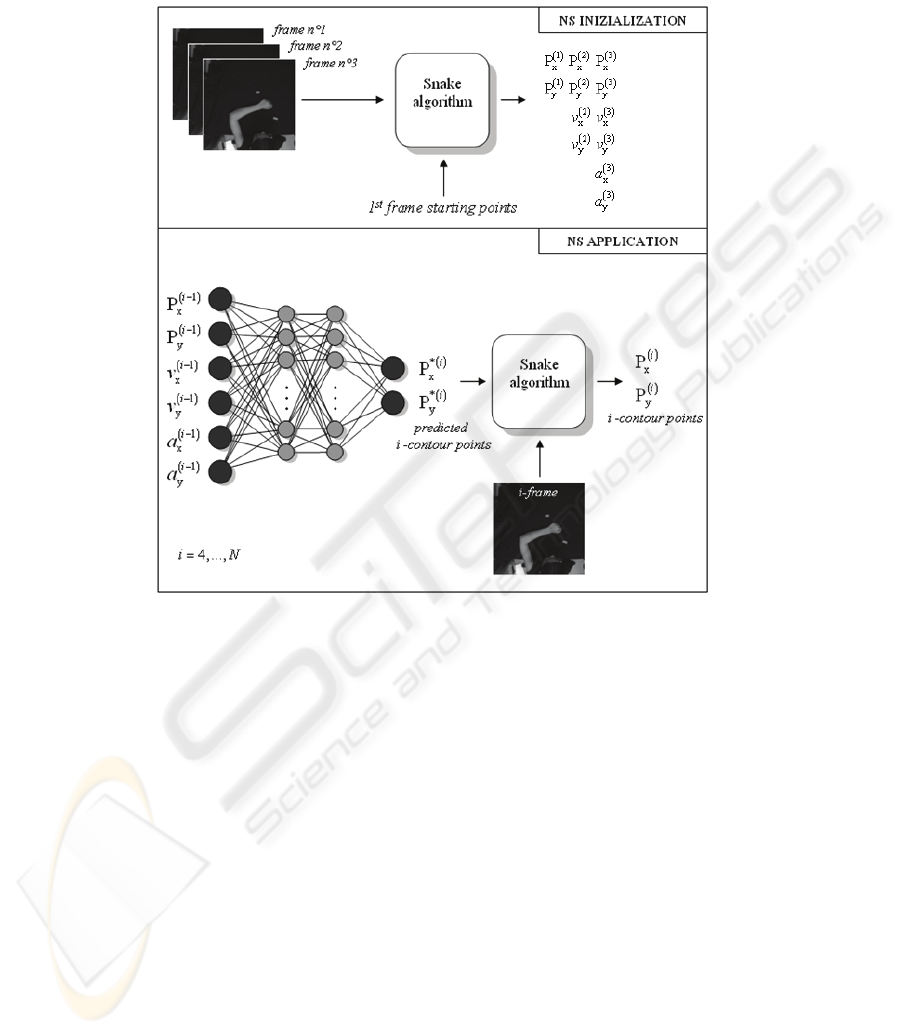
configuration prediction. After training, the ANN is used, frame by frame, to pre-
collocate the snake near the silhouette before the application of the traditional snake
model (figure 4).
The contour-points positions prediction, obtained through the ANN, is significant
especially in case of fast movements (ballistic) or video sequences with low frame
rate (i.e. webcams). Therefore, the usage of the trained ANN before the application of
the Snake algorithm allows to track the silhouette also in these situations. Since the
ANN inputs are constituted by the horizontal and vertical components of position,
velocity and acceleration of each contour point, the first three frames of the video
sequence are necessary for the initialization phase. In this stage the M starting points
are chosen in the first frame and the following two frames are elaborated with the
Snake algorithm obtaining the horizontal and vertical positions (P
x
and P
y
), velocities
(v
x
and v
y
) and accelerations (a
x
and a
y
). Then, the subsequent i frames (i=4,...,N,
where N is the total number of frames of the video sequence) are elaborated by apply-
ing the Snake algorithm on the output of the ANN (the M predicted contour points P
*
x
and P
*
y
). The result is the estimation of the silhouette over time. The spatial extremi-
ties of the M contour points, obtained by the Neural Snake approach, are then found
in order to estimate the close hand and shoulder trajectories. The positions of these
joints are in fact the inputs of the second block of the proposed method: the Neural
Controller.
2.2 The Proposed Neural Controller of the Upper Limb Model
The second part of the present work concerns the use of the trajectory’s parameter
information extracted by the Neural Snake algorithm. In order to simulate the activa-
tion of the plegic arm, a neural approach for modelling of the motor control of a hu-
99
man arm during planar movements has been used. For this purpose the Neural Snake
processing block has been integrated with a second system including a NN with a
biomechanical arm model [11].
Fig. 4. Graphical representation of the proposed algorithm for upper arm silhouette tracking.
This linked system is based on three main computational blocks (figure 5): 1) a paral-
lel distributed learning scheme that simulates the internal inverse model in the trajec-
tory formation process; 2) the Pulse Generator, which is responsible for the creation
of muscular synergies; and 3) the limb model based on two joints (two degrees of
freedom) and four muscle-like actuators.
An ANN (a Multi-Layer Perceptron, MLP-ANN with one input layer, one output
layer and two internal layers) has been used to represent the first computational block.
This first block represents the inverse internal model of the upper limb. It collects
proprioceptive information from the environment, and generates the specific neural
inputs necessary to obtain the desired motor task which should be carried out by the
arm. The Artificial Neural Network (ANN) can accomplish to this task on the basis of
its adaptation and plasticity features. The first layer of the ANN used for this model is
composed by 4 input units, representing the spatial information (in joints coordinates)
of the starting and the ending points gained by the analysis of the movement of the
real arm by means of the Neural Snake algorithm.
100
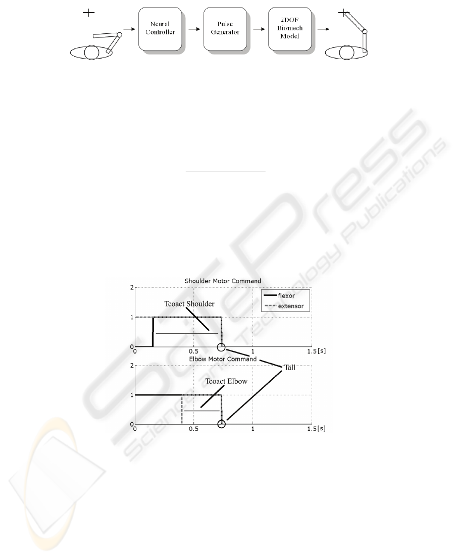
Fig. 5. Graphical representation of the proposed method for neural controller of the upper limb
model.
The transfer function chosen for every unit is the hyperbolic tangent: the output n
i
m
of
the i
th
neuron at the m
th
level is obtained from the weighted outputs of the (m - 1)
th
level, according to equation
1
1
2
1
0
1
−
∑
+
=
−
=
−
⋅−
m
j
m
N
j
m
j
nw
m
i
e
n
After the elaboration of two hidden layers composed by 20 neurons each, the output
layer provides 3 values, passed to the Pulse generator block, which transforms them
in the model of the train of the efferent nervous spikes necessary to activate the bio-
mechanical arm, thus inducing the generation of the planar movement.
Fig. 6. Neural activations of both the shoulder and the elbow muscle pair. Tall, total time of
neural activations, is the same for the two joints; the two Tcoact represent the interval of co-
activation of flexor and extensor muscle. The value of 1.5 s is the total observation time.
The third module corresponds to the model of a human upper limb, composed of a
skeletal structure together with a muscular structure. The skeletal model has a plant
structure composed of two segments (because the close hand joint is not considered),
with lengths L1 and L2, which represent the forearm and the upper arm respectively,
connected with two rotoidal joint. The planar joints that connect the two segments
can assume values in the angular range [0, π]. These values univocally identify the
101
Cartesian coordinates of the free end in the working plane by means of well known
direct kinematic transformation. The muscular system is thus based on 4 Hill’s type
muscle-like actuators, and establishes the dynamic relationship between the position
of the arm and the torques acting on each single joint [18].
The next figure depicts the profile of these neural activations having rectangular
shapes, and shows the duration of the entire voluntary task ranging in the interval 300
ms - 1 s. The three parameters generated by the ANN are: T
coact
shoulder
, that defines the
time of co-contraction between the agonist muscle and the antagonist muscle of the
shoulder joint, T
coact elbow
, giving the same information for the elbow joint, and Tall
that specifies the duration of the overall neural activations.
Body segment anthropometrics and inertias of both upper arm and forearm are now
taken from the scientific literature, taking into account the specific body height and
weight [19], but a key feature of the proposed approach is that an adequate model of
the arm of any specific subject can be obtained and used in the Neural Net.
The integration of the Neural Snake and the Neural Controller, that constitute the first
two blocks of the proposed stand-alone self-rehabilitation system, has been tested on
several experimental trials. The next paragraph describes the obtained results.
3 Experimental Results
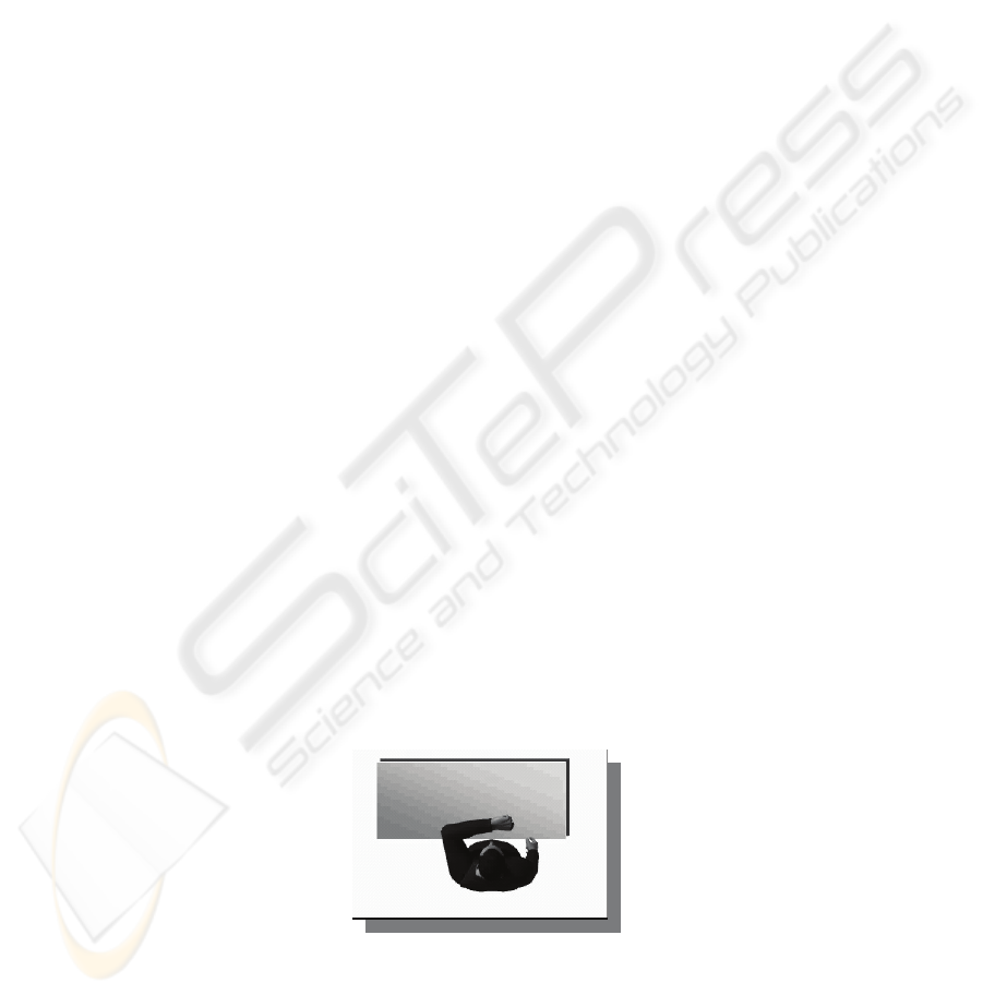
The markerless method has been firstly tested on synthetic video sequences in order
to evaluate its accuracy in tracking the arm silhouette, and after on a real context. The
synthetic videos, obtained with the program Poser®, present one virtual subject exe-
cuting movements similar to the real ones (that will be described below). Figure 7
depicts the model on which the method has been applied. A first video sequence, with
an high temporal resolution (60 fps) has been created as the training set for the snake
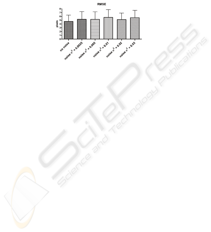
predictor ANN. Subsequently the proposed method has been tested on six different
videos, each one having a particular value of Gaussian noise (mean = 0, and variable
variance) added to it, and a temporal resolution of 30 fps. In literature results of the
application of contour detection algorithms are usually presented in a qualitative way
[15], [20]. In the present work the use of these synthetic videos makes it possible to
achieve quantitative results in terms of RMSE. Figure 8 shows the RMSE value for
each video sequence. The values obtained with the test carried out on synthetic videos
allow us to extend the application of the markerless technique to video sequences,
where real subjects are filmed by means of digital cameras.
Fig. 7. Upper view of the synthetic model used to test the proposed tracking system.
102
The tests have been done by recruiting 2 healthy subjects. During tests, the subject
sits on a chair in front of a desk whose height is the same of the subject’s armpit. In
this way the upper limb movements on the desk are planar. The subject’s trunk is
close to the desk border.
Fig. 8. RMSE values obtained from the analysis of the synthetic video sequences using the
tracking system. Pixel/cm ratio is 2.7. This means that the mean error value is less than 3 cm.
Three target points are set on the table surface and a digital video camera (Silicon
Imaging MegaCameras SI-3300RGB) records movements from an upper view. The
experimental protocol consists of a series of 3 fast reaching movements executed with
the left arm towards three different targets considering the centre of the closed hand
as the end-effector. The video sequence used for training the Snake predictor ANN
has been acquired with the temporal resolution of 60 frame/s. The proposed Neural
Snake technique has been applied on two video sequences acquired with the 30
frame/s sampling rate. The spatial resolution of the frames is 1024x1020 pixels. The
pixel/cm ratio is 13.5. Figure 9 shows the experimental setup.
The Neural Snake method has been applied on the video sequences and the close
hand and shoulder positions have been estimated over time. Figure 9 shows the re-
sults of the proposed silhouette detector and the obtained trajectories on the last frame
of the video sequence. The Cartesian coordinates of the three targets reached by the
subject’s arm are evaluated considering the shoulder as the centre of the reference
system. The new positions values are subsequently sagittally mirrored and passed to
the right arm Neural controller. For each pair of starting and target points of the three
trajectories, the motor control simulator generates the neural excitations that permit
the biomechanical right arm model to execute a movement similar to the one experi-
mentally acquired (figure 10).
103
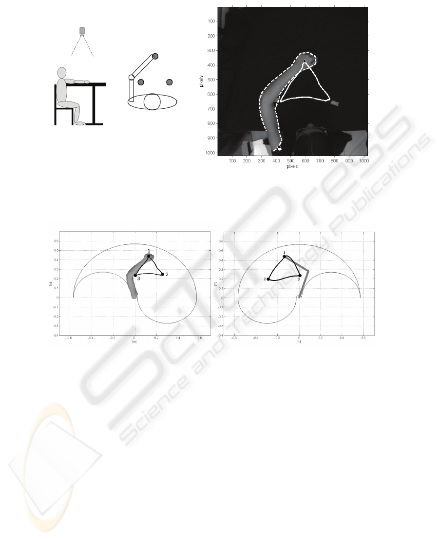
Fig. 9. On the left , experimental setup; on the right, upper limb Neural Snake (dot line) and
close hand and shoulder trajectories (solid line) on the last frame of the video sequence.
Fig. 10. Solid close hand trajectory (left) and the output of the Neural Controller: “plegic” arm
trajectory (right).
4 Conclusions
A new method finalised to the self-rehabilitation of the arm movements of hemiplegic
patients has been presented. The overall system is composed by three main blocks.
The first one is dedicated to the markerless analysis of the healthy arm during planar
movements and the extraction of kinematics parameters. In the second block a neural
controller makes use of these information in order to generate specific outputs neces-
sary to pilot a biomechanical arm model. First experimental results are particularly
encouraging: in the future the outputs gained by the neural controller will be used for
generating the electrical stimuli of the FES system which represents the third block of
the proposed approach, called TwinN-FES.
104

References
1. Bruce H Dobkin, Strategies for stroke rehabilitation, Lancet Neurol (2004), 3: 528–36
2. Nudo R, Wise B, SiFuentes F, Milliken G. Neural substrates for the effects of rehabilitative
training on motor recovery after ischemic infarct. Science (1996), 272: 1791–94.
3. Liberson WT, Hotmquest HJ, Dow M. Functional electrotherapy: stimulation of the per-
oneal nerve synchronized with the swing phase of the gait of hemiplegic patients. Arch
Phys Med Rehabil. (1961), 42:101–105.
4. Bogataj U, Gros N, Kljajic M, Acimovic R, Malezic M. The rehabilitation of gait in pa-
tients with hemiplegia: a comparison between conventional therapy and multichannel func-
tional electrical stimulation therapy. Phys Ther. (1995), 75:490 –502.
5. Wang RY, Yang YR, Tsai MW, Wang WT, Chan RC. Effects of functional electric stimu-
lation on upper limb motor function and shoulder range of motion in hemiplegic patients.
Am J Phys Med Rehabil. (2002) Apr;81(4):283-90.
6. A functional electric stimulation—assisted exercise therapy system for hemiplegic hand
function Gritsenko V, Prochazka A Arch. Phys.Med. and Rehabil. (2004), 881-885
7. Prochazka A, Gauthier M, Wieler M, Kenwell Z. The bionic glove: an electrical stimulator
garment that provides controlled grasp and hand opening in quadriplegia. Arch Phys Med
Rehabil (1997), 608–14.
8. Popovic D, Stojanovic A, Pjanovic A, Radosavljevic S, Popovic M, Jovic S, et al. Clinical
evaluation of the bionic glove. Arch Phys Med Rehabil (1999), 299–304.
9. Kurosawa K, Futami R, Watanabe T, Hoshimiya N. Joint angle control by FES using a
feedback error learning controller. IEEE Trans Neural Syst Rehabil Eng. (2005), Sep. 13
(3):359-71.
10. H. Gomi and M. Kawato, Neural network control for a closed-loop system using feedback-
errorlearning , Neural Networks, vol. 6, pp. 933--946, 1993.
11. I. Bernabucci, T.D'Alessio, S.Conforto, M.Schmid Controlling planar ballistic movements
by means of neural system. X Mediterranean Conf. on Med. and Biol. Eng. and Comp.
IFMBE Proceedings, MEDICON 2004 Ischia, Italy (2004)
12. M. Goffredo, M. Carli, S. Conforto, D. Bibbo, A. Neri, T. D’Alessio, Evaluation of Skin
and Muscular Deformations in a non-rigid motion analysis, Proceedings ISandT/SPIE's In-
ternational Symposium on Medical Imaging San Diego, California, USA. (2005)
13. W. Maa, X. Maa, S. Tsoa, Z. Panb, A direct approach for subdivision surface fitting from a
dense triangle mesh, Computer-Aided Design 36 (2004) 525–536
14. M. Goffredo, M. Carli, M. Schmid, A. Neri, Study of muscular deformation based on sur-
face slope estimation, Image Processing: Algorithms and Systems V - Electronic Imaging
2006 San Jose, California, USA (2006)
15. Kass M.,Witkin A., Terzopoulos D.: Snakes: Active contour models. Proc. 1st Int. Conf. on
Computer Vision (1987) 259–268
16. Lee A (2002) webpage www.virtualdub.org
17. Canny, J.: A Computational Approach to Edge Detection. IEEE Trans PAMI (1986) 679-
698
18. L. L. Massone and J. D. Myers "The role of the plant properties in arm trajectory forma-
tion: a neural network study," IEEE Trans. Sys. Man Cyb. vol. 26, pp. 719-732, 1996.
19. R. Drillis, R. Contini, and M. Bluestein, "Body Segment Parameters; a Survey of Meas-
urement Techniques," Artif Limbs, vol. 25, pp. 44-66, 1964.
20. Wagg, D. K. and Nixon, M. S. (2004) Automated Markerless Extraction of Walking People
Using Deformable Contour Models. Computer Animation and Virtual Worlds 15(3-4) pp.
399-406.
105
