
ONLINE HIERACHICAL CONTROL FOR LEGGED SYSTEMS
BASED ON THE INTERACTION FORCES
José R. Puga
Department of Electrical Engineering, Polytechnic Institute of Porto, 4200-072 Porto, Portugal
Filipe M. Silva
Department of Electronics, Telecommunications and Informatics, IEETA, University of Aveiro, 3810-193 Aveiro, Portugal
Boaventura R. da Cunha
Department of Electrical Engineering, University of Trás-os-Montes e Alto Douro, 5000-911 Vila Real, Portugal
Keywords: Legged robots, Biped locomotion, Online planning, Interaction forces.
Abstract: This paper presents a motion planning and control method with application in the field of legged robots. The
general aim is to explore a set of simple underlying principles that govern balance of posture and gait of
biped robots, and to develop control methodologies for such a highly unstable and non linear plants. The
proposed controller reflects a hierarchical structure based on the interaction forces between the foot and
ground and simple feedback rules used online. The algorithms are applied to a simulated 3-D leg model
with five degrees of freedom (DOF). The simulation analyses demonstrate the capability of the control
system to keep balance when the leg executes different tasks. To validate the proposed method several
aspects are investigated, such as the posture robustness on the level ground when subject to external
perturbations, the adaptation when standing in a moving platform and the improvements introduced by the
compensation of the tangential reaction forces.
1 INTRODUCTION
Biped locomotion, the core technology for a
humanoid robot, has attracted an enormous interest
around the world, both from the industry and the
academic communities. The major problems
associated with human-like walking results from the
high centre of gravity (COG) with a small contact
area to the ground. With other words, balance
maintenance is a central concern in order to engage
useful tasks, from standing upright posture to motion
goals. In what concerns control, the difficulty lies in
the uncertainty of the environment and the
limitations of the contact between the robot and the
environment. On the one hand, the advantages of
biped locomotion are well-known for irregular
terrains described by deterministic, but a priori
unknown models. On the other hand, the degree of
freedom formed between the foot and the ground is
unilateral and under-actuated, affecting the postural
stability (Goswami, 2004). The most prominent
stability measure to enhance trajectory-tracking
controllers and to analyse their stability is the
so-called zero moment point (ZMP) criterion
(Vukobratovic, 1990).
Current works in motion generation fall largely
into two categories: trajectory replaying and online
generation. The former is mainly characterised by
pre-planned trajectories that are then played back
during walking and modified online through
feedback (Hirai, 1998; Yamaguchi, 1999; Park,
2000). By contrast, the later generates a trajectory
online, feeding back the present state of the system
in accordance with the pre-provided goal of the
motion (Sugihara, 2002; Kajita, 2003). Planning and
control are executed in a unified way, although
requiring a larger amount of computation power.
Bearing these facts in mind, this paper aims to
explore a set of simple underlying principles that
261
Puga J., Silva F. and Cunha B. (2006).
ONLINE HIERACHICAL CONTROL FOR LEGGED SYSTEMS BASED ON THE INTERACTION FORCES.
In Proceedings of the Third International Conference on Informatics in Control, Automation and Robotics, pages 261-268
DOI: 10.5220/0001221702610268
Copyright
c
SciTePress

govern balance and to develop online control
methods for such a highly unstable and non-linear
plant. The approach followed in this paper consists
of studying a simple model but keeping enough
complexity to allow a clearly evaluation of the
control method. The algorithms are then applied to a
simulated 3-D robot model with a total of 5-DOF.
The main features of the proposed scheme are the
consideration of the interaction forces as the primary
control variable and the minimal dependency on
pre-programmed references.
The tasks to be performed include a variety of
motion goals specified in the intuitive Cartesian
space (e.g., hip coordinates, Centre of Gravity COG),
as well as in the joint space. The discussion includes
the choice of control principles, the selection and
grouping of control variables and measurements. The
scope of the paper covers the sagittal and lateral
planes for a robot model that stands itself on a
platform. The analysis will be carried out in a
dynamic simulation environment.
This paper is organised as follows. Section 2
describes the robot model, the sensorial requirements
and the tasks’ description. Section 3 presents the
online motion-control algorithm on which the
walking tasks are formulated. Section 4 discusses the
computer simulations used to illustrate the different
characteristics of the control algorithm. Section 5
concludes the paper and outlines the perspectives
towards future research.
2 SYSTEM AND TASK
DESCRIPTION
The control algorithms presented in this paper are
applied to a simulated 3-D robot model with 5-DOF
and 4-links (foot, shank, thigh and trunk). The Open
Dynamics Engine simulation library (Russell, 2004),
based on the Newtonian mechanics for articulated
rigid bodies, is used along with an interactive
graphical user interface. Figure 1 illustrates the
articulated system with a total weight of 5 kg and a
maximum height of 66 cm. The detailed parameters
of this model are summarised in Table 1.
Table 1: Robot and environment parameters.
Dimensions (m) Spring-damper model
Link
i
Mass
(kg)
lx
i
ly
i
lz
i
K
z
(N/m) B
z
(Ns/m)
Trunk 4,00 0.06 0.15 0.330 50.0×10
3
1000.0
Thigh 0,70 0.04 0.04 0.165 Friction model
Shank 0,23 0.03 0.03 0.142
MU
K
mu
f
Foot 0,07 0.12 0.08 0.023
1.20 2.50
Figure 1: Three-dimensional 4-link model.
2.1 Actuators and Sensors
The leg proportions and the structure were selected
as a result of the desired similarity with the human
body. In order to provide adequate mobility the
model considers five rotary joints: two joints at the
ankle whose axes are orthogonal (pitch ν, roll ψ),
one at the knee (pitch ν) and two at the hip (pitch ν,
roll ψ). The contact of the foot with the constraint
surface is modelled through linear spring-damper
systems in the horizontal and vertical directions.
The specification of the actuators was obtained,
given the desired goals, by adjusting the values of
the maximum power, maximum torque and electrical
time-constant. These actuation constraints are
considered to evaluate the system’s ability when
performing a desired task. At the same time, a
walking robot can not afford to move on without
sensor feedback for even a smallest time segment.
While in motion or just standing still the robot must
continuously check the balance of the body. To this
purpose, it is considered feedback control from
several sensors, including angular position in each
joint, a three-axis inclinometer attached to the trunk
section and four force sensors inserted in the foot
corners. The sensors in the foot corners provide
information about the ground reaction forces and the
location of the centre of pressure (COP), as well as
about the full contact of the foot with the ground.
The inclinometer, the angular position in the joints
and the detention of full contact between the foot and
the ground provides the system with the ability to
detect the ground slope.
2.2 Task Description
A complete classification of possible tasks to be
performed is not feasible in view of the large variety
of cases that may occur, nor would such a
ICINCO 2006 - ROBOTICS AND AUTOMATION
262

classification be really useful to find a general
strategy of control. On the other hand, systems
capable of general legged locomotion are often
redundantly actuated. The immediate question is
how to exploit and coordinate the multiple degrees of
freedom. In general, it is observed that the joints
nearest to the ground (ankle and knee) are closely
related to the mobility and stability of the system,
and the more distant from the ground (hip) has a
compensation mechanism purpose.
The tasks to be performed include a variety of
motion goals specified in the intuitive Cartesian
space, both for the hip coordinates and the COG. A
generic robot task requires the execution of specific
motions prescribed in the joint space, as well. In the
present study, we will exploit mainly voluntary
movements such as the trunk inclination, either
sideways or front-backward. Accordingly, the task
description (refer to Figure 2) is provided with a first
block ensuring the fundamental motion directives
and a second block concerning individual joint
motions. However, it must be pointed out that all
five actuators will contribute to attain the motion
directives specified in the Cartesian space.
In this paper, it is assumed that the goal of the
articulated system (support-leg and trunk) is to
achieve a stable behaviour for a variety of motion
goals specified for the hip section, the centre of
gravity and other points, while it adapts to discrete
disturbances. More concretely, the desired task to be
performed consists of movements of crouch from
standing and then thrusts the body upwards to
assume an upright position again. Moreover, the
robot foot is assumed to be on two different support
surfaces: level ground and inclined ground. The main
goals are to investigate the posture robustness on the
level ground when subject to external perturbations,
the system’s adaptation when standing in a moving
platform and the improvements introduced by the
compensation of tangential forces.
A useful means to assess balance skill and gain
insight into postural control is by applying external
perturbations and recording reactions. One typical
disturbance experienced by a service robot is a
change in body mass. To demonstrate the capability
of adaptation to changes in mass, the system is
submitted to both loading and unloading of an
external load. There are other perturbations due to
external forces applied while the system is moving.
3 CONTROLLER BASED ON THE
INTERACTION FORCES
3.1 Highlight of the Method
Biped robots exhibit complex dynamic phenomena
that make difficult their analysis and control. A
major problem is the difficult relation between
planning and stability, namely the robot cannot
follow arbitrary motion commands. This difficulty
has justified a different line of thought where the
skill of locomotion emerges from the physical
interaction between the machine and the
environment itself (Fujimoto, 1998; Park, 2001).
In this line of thought, one approach based on the
interaction forces between the foot and the ground is
investigated. We emphasize the main role of these
forces as the key element through which new control
strategies are proposed to provide the required level
of compliance, adaptation and dynamic stability. The
proposed controller reflects a hierarchical structure
using force as the primary control variable and
simple feedback rules (Figure 2).
A block diagram of the resulting controller is
sketched in Figure 2, revealing the parallel operation
of a force control loop and a position control loop.
Hence, the control signal to the actuators is
composed of a force control action and a motion
control action integrated in a hierarchical way, as
follows:
f
fpp
KK
τ
ττ
=+
(1)
where K
f
and K
p
are positive activation constants
(unitary sum) that define the dominance in the
contribution to the output. This parallel composition
of control actions aims at exploit the redundancy of
the system: a given actuator can be utilized to meet
more than one task requirement (thus providing
redundancy resolution).
A relevant feature of the proposed method is the
possibility of performing both indirect and direct
force control. The former is obtained via motion
control and without explicit closure of a force
feedback loop (solid line). The later, instead, offer
the possibility of controlling the contact force to a
desired value, thanks to the closure of a force
feedback loop (dashed line).
The position controller uses a time-dependent
algorithm that involves the tracking of pre-computed
trajectories using a PID control law. The following
subsection is aimed at presenting the implementation
ONLINE HIERACHICAL CONTROL FOR LEGGED SYSTEMS BASED ON THE INTERACTION FORCES
263

Task Description
q
T
J
OFF-LINE
Hierachical Position/Force Control System
Cartesian
Space
Joint
Space
MOTION
GOALS
ON-LINE
Force Virtual
References
+
Position
Controller
Robotic System
Direct
Kinematics
Robot
Model
Force Sensor/
Environment
f
Force
Controller
Figure 2: Blocks diagram of the hierarchical control
scheme.
of the force interaction control with reference to their
properties.
3.2 Force Interaction Control
As far as the force control is concerned, the tasks to
be performed depend on motion goals defined in the
Cartesian space. On the other hand, the variables to
be controlled are the reaction forces distributed along
the foot’s corners. In order to ensure the proper
behaviour through the execution of an interaction
task, the reference variables must be generated
online in result of the demands imposed to the
system. These are the variables that some force
control law must follow.
For the present purposes, the reference forces are
calculated through suitable actions on the position
errors in both horizontal and vertical directions. The
resultant normal reaction force is calculated from the
errors measured in the vertical coordinate (z-axis)
using a linear control law:
ez
dt
d
KezdtKezKf
f
d
t
f
i
f
P
ref
n
++=
∫
0
(2)
Here,
ez
is the vertical position error given by
)( zz
ref
−
where
ref
z
and z are the desired and real
vertical coordinates,
ref
n
f
is the reference normal
force, and
f
p
K
,
f
i
K
and
f
d
K
are the proportional, the
integral and the derivative appropriated constant
feedback gains, respectively.
On the other hand, the desired location of the
centre of pressure (COP) is calculated from the
errors measured in the horizontal coordinates (x and
y axis), as follows:
ex
dt
d
KexdtKexKCOP
COP
d
t
COP
i
COP
P
ref
++=
∫
0
(3)
where
ref
COP
is the reference centre of pressure, ex
is the horizontal position error of the COP given by
)( xx
ref
− , where
ref
x
and
x
are the desired and
real horizontal coordinates,
COP
p
K
,
COP
i
K
and
COP
d
K
are
the proportional, integral and derivative feedback
gains, respectively. All the feedback gains in
equations 2 and 3 were tuned with a standard
method. Finally, the reference COP is actively used
to calculate the distribution of the total reaction force
along the extremities of the support foot.
Having defined the reference forces, there are
many different ways to implement the compliance
control. This paper contributes with one strategy that
considers only the indirect force control. In spite of
the enhanced disturbance rejection provided by an
inner force control loop, a compliant behaviour can
be successfully achieved with the proposed solution.
In this line of thought, the signal forces obtained
for each corner of the foot are directly transformed
into joint torques by using the transpose of the
Jacobian matrix:
τ
=
=
∑
4
1
T
f
ii
i
J
f
(4)
Here,
i
J
is the Jacobian matrix which transforms
the differential variation in the joint space into the
differential variation of the end-effector’s frame i
(each foot corner) with respect to the reference frame
(located at the hip). The subscript
T
denotes the
transpose of a matrix. In the above treatment, it has
been implicitly assumed that the friction is large
enough to avoid any foot’s slippage. Nevertheless,
the general form of f
i
used in (4) may contain a
tangential force term. Further, the equation requires
lower computation than inverse kinematics or
dynamics equations and it is well-behaved since, for
a given force vector, a corresponding torque vector
can always be obtained even if the robot is in a
singular configuration.
In other words, the support leg “feels” the forces,
while the controller distributes them as driving
torques in order to regulate the desired high-level
directives. This strategy was generalised to all
degrees of freedom, from the ankle until the hip
joints. It is worth noting that, after some analytical
simplifications, a computationally simpler control
law can be derived as function of the desired normal
forces, tangential forces and COP. For example, the
output torque for the ankle joints can be written as:
() ()
cos sin
ref
ref ref
azhx
P
ref
ref d ref
azhYaza
P
xf lf
yf lf f
υ
ψ
υψ
τ
τ
θθ
=− ⋅ − ⋅
⎡⎤
=+ −⋅
⎣⎦
(5)
where
ref
P
x
and
ref
P
y
are the reference COP,
ref
x
f
,
ref
y
f
and
ref
z
f
are the reference interaction forces,
a
υ
θ
and
a
ψ
θ
are the pitch and roll ankle angles respectively,
ICINCO 2006 - ROBOTICS AND AUTOMATION
264
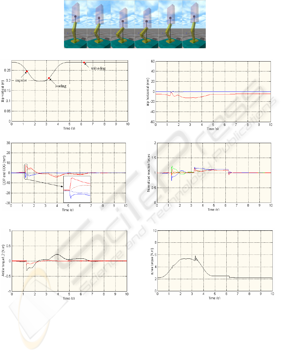
(a) Movement sequences with the hierarchical integration.
(b) Hip’s vertical position under disturbances (left) and hip’s horizontal position (right): along the x-axis (in red) and along the y-axis (in blue).
(c) Location of the COP (solid line) and projected COG (dotted line) along the x-axis (in red) and along y-axis (in blue). Normalized normal
reaction forces at the corners of the foot: back right (in yellow), back left (in blue), front right (in green) and front left (in red).
(d) Temporal evolution of the torques at the ankle joints (left) and knee joint (left).
Figure 3: Simulation results for the robot standing on level ground when subject to external perturbations.
and l
h
is the foot’s height. This expression can be
useful whenever is necessary to sacrifice mobility
goals to ensure postural stability.
3.3 Hip Control
The trunk section has a particular role both in the
mobility and the stability of the overall system. On
the one hand, it has a great influence on the location
of the COG, what can be helpful to achieve a given
task. On the other hand, the postural stability
imposes limitations to the trunk motion: its
inclination must remain within a limited range of the
angular space and, when operating in steady state, it
must converge to a limit cycle. The idea of the
parallel control is to conciliate two imperatives –
ONLINE HIERACHICAL CONTROL FOR LEGGED SYSTEMS BASED ON THE INTERACTION FORCES
265

mobility and stability – that in many circumstances
are contradictories.
In this regard, the control structure of the trunk
section integrates also the control actions designed
on the basis of the position controller, as described
before. It is the sum of both components that actuate
over the hip joints, while providing some sort of
redundancy resolution. For certain motion tasks, it
can be necessary to adopt the same strategy with any
other joint.
4 SIMULATION RESULTS
In order to verify the effectiveness of the proposed
controllers several simulations are carried out.
Motivated by applications in biped locomotion, this
section focuses on the posture robustness of the
simplified model on the level ground when subject to
external perturbations, on the system’s adaptation
when standing in a moving platform and on the
improvements introduced by slip compensation.
4.1 Robustness to Perturbations
The first analysis illustrates the properties of the
proposed control scheme when the system is on the
level ground subjected to unpredictable
perturbations.
The results displayed below are based on the
following path: the system is standing, moves down
and up again to the initial posture in 5 seconds. The
initial state is set to
0.29
hip
zm=
and the desired
()
,
GG
x
y
should be zero along the motion. The motion
planning is accomplished by prescribing the desired
trajectories using sinusoidal-based functions. The
controller’s performance is evaluated by applying
two unpredicted perturbations. The first perturbation
corresponds to a horizontal force of
(
)
(
)
=+ −,10,5
xy
F
FN
applied to the hip section at a pre-
defined instant of time (1.25 s) and sustained for
20 ms. At the same time, an external virtual load of
10% of the body mass is added instantaneously on
the hip at a pre-defined instant of time (3.25 s) and
removed when standing (6.25 s). The simulation
results are shown in Figure 3. It is observed that the
actual hip height profile was well-achieved, and the
system makes the necessary postural adjustments.
The system is only displaced by a few millimetres
and it has stabilised shortly after the push. The
results also demonstrate that mass adaptation is
feasible, for both loading and unloading of an
external load. The control method is able to
minimise the sway by generating a shear force
quickly at the ground to counteract the perturbation.
It depends on the latency at which it starts to resist
the push and the rate at which this force can be
increased. The last graphs show the temporal
evolution of the computed joint torques. Given the
proposed task, it is required a knee torque value that
is significantly greater than the others, while the
lateral joints require almost no torque.
4.2 Adaptation to Inclined Ground
The second analysis illustrates the emergence of an
appropriate behaviour when the system stands on an
inclined ground. The task performed is the same as
before, while the control system relies on the
inclinometer data to estimate slope changes. The
complete information data is depicted in Figure 4
(the top graph illustrates the movement sequence).
The task performed comprises forty cycles for
the robot’s motion (period of 3 s) and sixty cycles for
the platform’s motion (period of 2 s). The robot is
placed at a distance of 30 cm from the platform’s
rotational axis. Further, sinusoidal movements are
specified to the hip joints both in the sagittal and
lateral planes. For the roll axis, the amplitude is
0.15 rad and the period 3.5 s. For the pitch axis, the
amplitude is 0.1 rad and the period 5 s. The phase
planes represented in Figure 4-(e) show the limited
amplitude of the trajectories in each joint.
In summary, the proposed control scheme
demonstrates self-adaptation and robustness against
external forces and load changes. The automatic
adaptation of the proposed controller to inclined
grounds represents another relevant property.
4.3 Tangential Forces Compensation
In the third analysis, we study the influence of the
tangential forces and how they are regulated in the
proposed control scheme. Therefore, contact force
measurements are fully exploited hereafter to design
the indirect force control.
The objective is to thrust the body upwards to
assume an upright position, while regulating the
tangential reaction forces (zero tangential force) for a
short period of time (160 ms). The simulation results
are shown in Figure 5. The graphs show the
improvements induced on the tangential component
that, whereas the normal component remains
unchanged. In view of the previous results, the
introduction of these control variables could help to
avoid the foot’s slippage.
ICINCO 2006 - ROBOTICS AND AUTOMATION
266
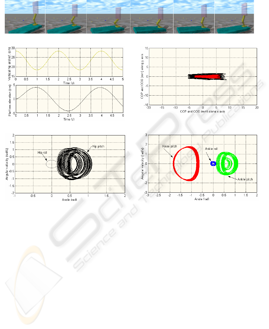
(a) Movement sequence during two seconds (the complete motion rounds 120 seconds).
(b) Hip and platform (point of support) positions for a complete cycle.
(c) Trajectory of the COP (in black) and COG (in red).
(d) Limit cycles observed in the hip joints.
(e) Limit cycles observed in the knee and ankle joints.
Figure 4: Simulation results obtained for the robot standing on inclined ground with variable slope.
5 CONCLUSIONS
This paper investigated motion-control algorithms
with application in the field of biped locomotion.
Topics such as the algorithm robustness and postural
stability were discussed through several experiments.
From the results achieved a few remarks ought to be
made. First, the Force Interaction Control is effective
to generate the desired leg motion, while assuring the
desired postural balance. The combination of
position and force control algorithms is essential to
exploit the system’s redundancy. Second, the results
illustrate the capability of the system to adapt to
external forces and to changes in the body mass.
Third, the results obtained provide an intuitive
understanding of the postural adaptation when the
system stands on an inclined ground with variable
slope.
Ongoing research focuses in two main directions:
i) to extend this study to a biped locomotion system;
ii) to apply the proposed schemes to different
walking tasks. Therefore, issues like active postural
recovery, inner force control loop, advanced
algorithms such as adaptive and learning strategies
are currently being challenged.
ONLINE HIERACHICAL CONTROL FOR LEGGED SYSTEMS BASED ON THE INTERACTION FORCES
267
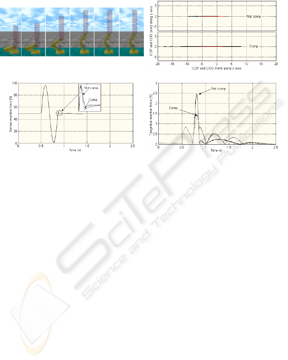
(a) Movement sequence for a fast (400 ms) thrusting the body upwards
to assume an upright position.
(b) Trajectory of COP (in black) and COG (in red).
(c) Time evolution of the normal reaction forces.
(d) Time evolution of the tangential reaction forces.
Figure 5: Simulation results obtained for the robot standing on level ground with the regulation of the tangential forces.
ACKNOWLEDGEMENTS
The first author would like tacknowledgege FCT,
FEDER, POCTI, POSI, POCI, POSC and ISEP for
their support to R&D Projects and GECAD Unit.
REFERENCES
Goswami, A., V. Kallem, 2004. Rate of Change of
Angular Momentum and Balance Maintenance of
Biped robots. In the Proc. IEEE Int. Conf. on
Intelligent Robots and Systems, pp 3785-3790.
Vukobratovic, M., et al., 1990. The book, Biped
Locomotion – Dynamics, Stability, Control and
Application, Springer-Verlag.
Hirai, K., et al., 1998. The Development of Honda
Humanoid Robot. In the Proc. IEEE Int. Conf. on
R&A, pp. 1321-1326.
Yamaguchi, J-I., et al., 1999. Development of a Bipedal
Humanoid Robot – Control Method of Whole Body
Cooperative Dynamic Biped Walking. In the Proc.
IEEE Int. Conf. Robotics & Automation, pp. 368-374.
Park, J.H., H.C. Cho, 2000. An On-line Trajectory
Modifier for the Base Link of Biped Robots to
Enhance Locomotion Stability. In the Proc. IEEE Int.
Conf. Robotics & Automation, pp. 3353-3358.
Sugihara, T., Y. Nakamura, H. Inoue, 2002. Realtime
Humanoid Motion Generation Through ZMP
Manipulation Based on Inverted Pendulum Control. In
the Proc. IEEE Int. Conf. Robotics & Automation, pp.
1404-1409.
Kajita, S., et al., 2003. Resolved Momentum Control:
Humanoid Motion Planning Based on the Linear
Angular Momentum. In the Proc. IEEE Int. Conf.
Intelligent Robots and Systems, pp. 1644-1650.
Russell, S., 2004. Open Dynamics Engine v0.5, 29 May,
2004. http://www.ode.org.
Fujimoto, Y., A. Kawamura, 1998. Robust Biped Walking
with Active Interaction Control between Foot and
Ground. In the Proc. IEEE Int. Conf. on R&A, pp.
2030-2035.
Park, J., 2001. Impedance Control for Biped Robot
Locomotion. IEEE Trans. on Robotics & Automation,
vol. 17, n. 6, pp. 870-882.
ICINCO 2006 - ROBOTICS AND AUTOMATION
268
