
FAULT DETECTION OF THE ACTUATOR BLOCKING
Experimental Results in Robot Control Structures
Matei Vinatoru, Eugen Iancu
Faculty of Automation, Computers and Electronics, University of Craiova,
RO - 200396, Craiova, str. A. I. Cuza, nr.13, Romania
Keywords: Control system, robotic arm, fault detection and isolation.
Abstract: In this paper is presented an algorithm, which allows for a certain robotic structure, under the terms of an
actuator blocking occurrence during the operation, either a correct positioning (if it is possible) or a
positioning in an acceptable proximity of the desired coordinates by minimising an optimal criteria
(through the adequate commands to the functional elements). The paper is proposing the synthesis of the
commands for a poly-articulated robotic arm (3 segments). First, a workspace analysis is made, then is
presented the algorithm for the actuators, first in the terms of a normal operation (finding the optimal
motions) and second in the terms of the blocking of some robotic segments.
1 INTRODUCTION
The correct positioning of the robot control arm is
critical to the efficient operation in the applications
of poly-articulated robot arms. One of most impor-
tant problem in robot control is the detection and
isolation of faults occurring in the actuators. In this
case it is necessary to develop a control algorithm for
certain robotic structure, under the terms of actuator
blocking occurring during the operation. This
algorithm must provide a correct positioning of the
gripper or a positioning in an acceptable proximity of
the desired coordinates using an optimal criterion.
The fault detection and isolation (FDI) problem is an
inherently complex one. Good diagnostic performan-
ces without installing supplementary equipment,
force the diagnostic tools developers to use
techniques available to process all information that is
"hidden" in the technological process. Numerous
approaches have been developed to address the
problem of FDI in dynamically systems, including
the fault trees and parity space techniques
(Viswanadham, 1987, 1988), Kalman filters (Meril,
1984), and detection filters (Iserman, 1997), etc.
This paper describes the application of a fault de-
tection and isolation method based on linear or non-
linear parameter model of the robot arm. A new
closed loop control method achieves the actuator's
fault isolation and control in fault conditions.
2 FAULT DIAGNOSIS
A fault causes degradation in system behaviour but
does not necessarily cause complete failure of plant
operation. The system may continue functioning to a
lesser degree, though failure may occur if a fault is
not detected in time. The tasks of a fault detection
system are (Vinatoru, 1997), (Ivanescu , 2000):
- Fault detection - a binary indication if the fault is
present or the system is fault-free.
- Fault isolation - that means the knowledge of
which sensor or actuators have failed.
- Synthesis of commands in fault conditions which
must assure the viability of the system (possibly in a
slightly degraded manner).
In figure 1 is presented a generalised structure of
the model based on fault detection and isolation.
In the design of automatic control systems, a
great emphasis is put on the structures capable to
detect and isolate fault conditions. The new solutions
can be classified in two different categories:
a) Fault detection and identification using dedicated
observers, detection and identification algorithms;
b) Fault management using FDIM architecture and
simulation results.
For the later category, in figure 2 we present a
structure for fault detection and isolation that assures
fast detection of a fault described thru a parameter in
the mathematical model.
548
Vinatoru M. and Iancu E. (2006).
FAULT DETECTION OF THE ACTUATOR BLOCKING - Experimental Results in Robot Control Structures.
In Proceedings of the Third International Conference on Informatics in Control, Automation and Robotics, pages 548-551
DOI: 10.5220/0001217505480551
Copyright
c
SciTePress
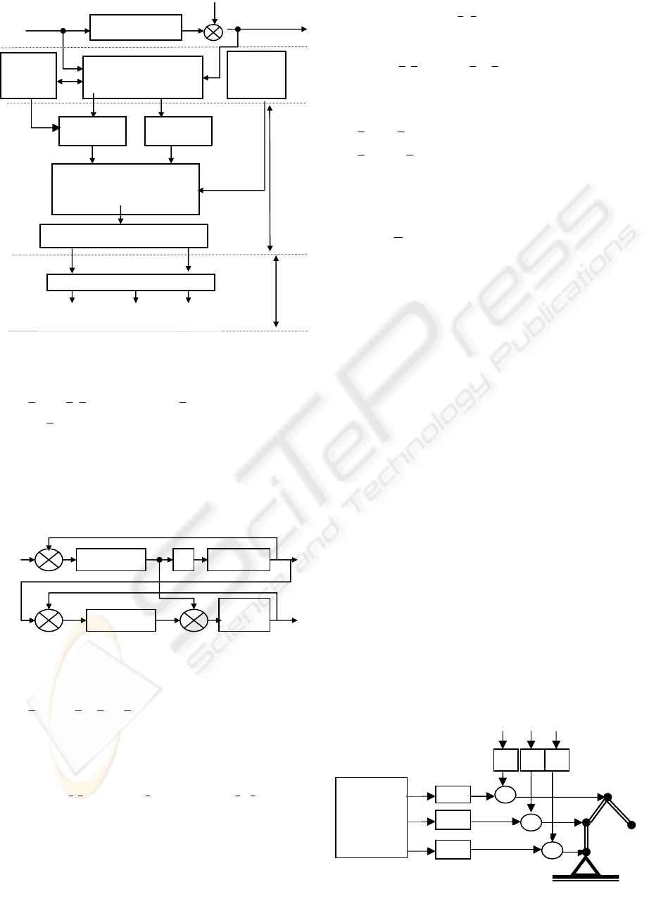
Let consider the plant described by the system:
),,(
α
c
xxfx = ; xCy
T
.= (1)
where
x is the state vector, y the measurable output,
α is a fault parameter and
c
x is the control command.
The real controller (PI type to ensure the steady state
errors equal with zero), is described by:
)()( yvKyvKx
IRc
−
+−=
(2)
where v is the set point of the control system.
The control structure for fault detection (fig. 2)
includes a plant model described by:
),,(
1 mccmm
xxxfx
α
+=
;
m
T
m
xCY ⋅= (3)
and the control signal:
)()(
1 mImRc
yyKyyKx −+−=
(4)
Replacing variables
m
yandy
in (6) we get:
)(),
1
,(),,(
1 m
xx
mc
x
m
xf
c
xxf
c
x
T
C
I
K
T
C
R
K
T
C
R
K −+−=
αα
(5)
The FDI control structure, if designed properly,
will modify the control signal x
c1
to obtain
0)(lim ==
∞→
tee
t
mms
. Therefore,
Y
s
=Y
m
s
0)( →−=−⇒
m
xx
T
C
m
YY
(6)
In this case, considering the steady state regime we
get:
[
]
0),,(),,(
1
0
=−
→
mcmc
t
xxfxxf
αα
lim
(7)
Using the linear model system (8) of the
equations (1) and (3):
mcicmm
c
dxbxbxAx
dxbxAx
α
α
⋅+⋅+⋅+⋅=
⋅+⋅+⋅=
(8)
after a few simple transformation in equations (7)
and (8) we get the diference between faulty
components real
α and modelled α
m
:
cs
x
d
b
m
⋅=−
αα
(9)
From the precedent analysis it results:
- the plant model shall reproduce the real plant ;
- the FDI control structure shall be asymptotically
stable, using the plant model controller;
- the response time of the FDI structure shall be
smaller than the response time of the real plant;
- the perturbations that appear in the real process
shall be included, as much as possible, in the model
structure.
3 SYSTEM ANALYSIS WITH
FAULT ACTUATORS
For analysis of the behaviour of the robot arm, when
one or many joints are blocked, we consider the
configuration presented in fig. 3. From this figure,
for the command
θ
ir
we can write the relations (10):
1,2,3i ,k)k1(
0iiiiir
=
θ
+
θ
−
=
θ
(10)
in which: k
i
= 0, for fault free actuator; k
i
= 1, in fault
conditions and the actuator blocked in θ
i0
position.
In figure 3,
θ
ir
has the significance of the real
command for the joint i. For the case when k
i
= 1, we
can simulate one actuator that don't work and remain
in blocked position
θ
i0
. In conclusion, the occurance
of one fault is equivalent with a jump modification
of the state equation structure for the actuators.
-
-
e
Controller 1 PLANT
EE
v
x
c
y
x
c1
e
m
Controller 1m
Plant
Model
y
y
m
Figure 2: FDI Structure.
+
Robot
arm
Figure 3: Synthesis of failed actuators.
Algorithm
for
commands
synthesis
1-
k
1
1-
k
2
1-
k
3
θ
1
θ
2
θ
3
θ
10
θ
20
θ
30
k
1
θ
1r
θ
2r
θ
3r
+
k
2
k
3
+
Modelling
Figure 1: Generalised structure of model based faul
t
detection and isolation methods.
State
estimation
Parameter
estimation
GENERATION OF:
Errors signals
Residuals
FAULT DECISION
FAULT DIAGNOSIS
PROCESS
MODEL OF
OBSERVED
PROCESS
Model
of normal
process
Model
of faulty
process
Fault detection
Fault diagnosis
Fault
diagnosis
Fault
diagnosis
Fault
diagnosis
Fault timeFault type
Fault
signature
U
N
Y
FAULT DETECTION OF THE ACTUATOR BLOCKING - Experimental Results in Robot Control Structures
549
The vector of commands has the expression:
⎥
⎥
⎦
⎤
⎢
⎢
⎣
⎡
⎥
⎥
⎦
⎤
⎢
⎢
⎣
⎡
⎥
⎥
⎦
⎤
⎢
⎢
⎣
⎡
+−==
30
20
10
3
2
1
)(
3
2
1
θ
θ
θ
θ
θ
θ
θ
θ
θ
D
K
D
KI
r
r
r
r
Θ
(11)
in which: K
D
=diag [k
1
k
2
k
3
] is called the fault
matrix. If
0K
D
≡ the system has no fault.
The vector:
[][ ]
3020100
θθθ
=Θ
T
(12)
represent the blocking position of the actuators.
Therefore, we can study the behaviour in fault
conditions, using a fixed fault matrix.
4 STRATEGY OF CONTROL IN
FAULT CONDITIONS
Using the equations of robotic arm joints and the arm
tip (Ivanescu 2000), we define the following fault
situations and the domains of the fault free joints.
Zone I – first joint blocked (J
1
):
)
π
,(θ)
π
,(θblockedθ
2
0
3
,
2
0
2
,
1
∈∈− (13)
Zone II – second joint blocked (J
2
):
)
π
,(θblockedθ)
π
,(θ
2
0
3
,
2
,
2
0
1
∈−∈ (14)
Zone III – third joint blocked (T):
blockedθ)
π
,(θ)
π
,(θ −∈∈
3
,
2
0
2
,
2
0
1
(15)
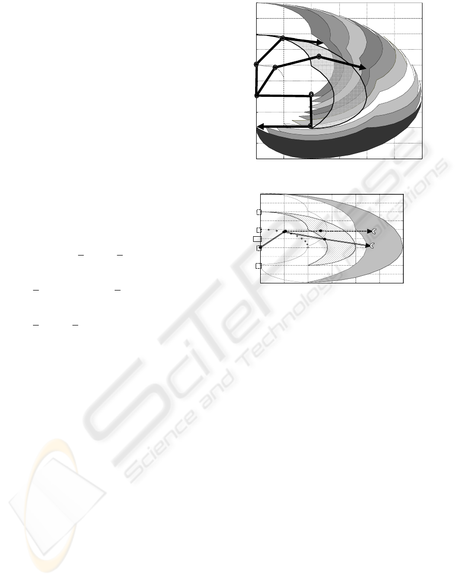
The equation of arm tip (T) defines the limits of
the work areas of the arm tip. For the case when
θ
i
=0
0
(suppose that i joints are blocked in this
positions, i=1, 2, 3), these areas are presented in
figure 4. There is a part of the fault free space of arm
tip (zone 0) that cannot be covered. In figure 4 it is
presented the movement of the zone I as function of
the
θ
1
parameter modifications. In the figure 5 it is
presented the work area for the joint 3 (J
3
) and the
arm tip (T) for the situation when
θ
3
is blocked at
90
0
. The border of each zone is a reunion of quarter
circle arcs with well known centre and radius. In this
case the strategy of control presented by the same
authors in (Ivanescu 2000) can be simplified. The
proposed algorithm is presented in following steps:
Step 1. Setting up a database in the memory of the
robot control computer with the border of the robot
fault zones, and the rotation centres.
Step 2. Setup the control structure presented in fig.3
of paper (Ivanescu, 2000).
Step 3. The residual vector
)t(r created by “Fault
detection and isolation block” offers the number
()
3,2,1k ∈ of blocked joint.
Step 4. Checking if the final position
(
)
3
k
3
k
y,x
of the
robot arm tip is inside of the border of the zone k.
If the result is “NOT” the computer generate an
alarm signal “Can’t touched the final position”. If
the result is “YES” the computer executes the control
algorithm, (Ivanescu, 2000), but only the step for
fault free joints. In figure 5 is presented the
movement of the robot arm tip for initial conditions I
to position 1 by
1
θ
and θ
2
control (θ
3
is blocked at 0
0
)
and the next step is the movement of the arm tip
from 1 to 2 only with control
Δθ
2
because the points
1 and 2 are situated in the intersection of zone III for
0
3
=
θ
and zone I for θ
1
=fixed in the position of last
command for point 1.
5 APPLICATION OF ROBOT
MODELS
Our goal is to detect the faults by measuring the
accessible process variables in real time. For the
given process, these variables are the actuator's
positions θ
1r
, θ
2r
, θ
3r
and the griper position X
g
(figure 3). There is a strong interdependence between
these variables and the possible defects occouring in
0 0.5 1 1.5 2 2.5 3
-2
-1 .5
-1
-0 .5
0
0.5
1
1.5
2
2.5
3
80-90
70
-
80
50-60
0-10
Area J3
Area T
Figure 4: The movement of Zone I for θ
1
∈(0-90).
0 0.5 1 1.5 2 2.5 3
-2
-1.5
-1
-0.5
0
0.5
1
1.5
2
2.5
3
Figure 5: The robot control in fault condition (θ
3
=0).
ICINCO 2006 - ROBOTICS AND AUTOMATION
550
the control equipment, and this impose an adequate
method to choose the fault measurable outputs pairs.
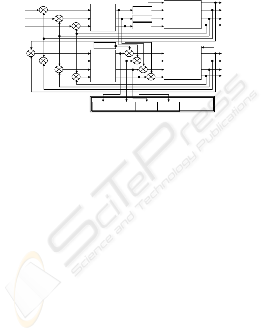
In order to chose the corect perturbation-output
pairs, we use the sensitivity matrix method. For
experimental studies we implemented the fault
detection structure presented in figure 6, as extension
of the elements presented in the first part of the paper
(figure 2).
The structure can be easily implemented in the
robot supervising computers that collect information
about the robot arm. This structure does not require
supplimentary equipment, and it can be implemented
for the existing monitoring digital control system of
the robot.
6 CONCLUSIONS
In this paper it is presented an extension of the
algorithm developed in authors’ paper (Ivanescu,
2000). The results of this algorithm are:
- The resolute decision in fault conditions to continue
or not the movement of robot arms
- The diminution of the control times
- The diminution of memory space allocated for
database.
- The use of a simple algorithm for control imple-
mented on a small controller.
In the future it is possible to develop some control
algorithms in fault free conditions using the fault
zone definitions. As a result of this analyse it is
possible to develop the control of the robot arm only
with one or two joint command.
REFERENCES
Chow Y., A.Willsky, 1984. Analytical Redundancy and
Design of Robust Failure Detection Systems, IEEE
Trans. Aut. Contr., AC-29(7), pp. 603 – 614.
Isermann, R., 1997. Supervision, fault detection and fault
diagnosis methods - An introduction, Control
Engineering Practice, 5(5), pp. 639 – 652.
Ivanescu, M., M. Vinatoru, E. Iancu, 2000. Robotic Arm
Control in Fault Condition, Proceedings of the
IASTED International Conf. Artificial Intelligence and
Soft Computing, Banff, Canada, vol.I, pp. 361-365.
Merrill, W., B. Lehtinen, J. Zeller, 1984. The Role of the
Modern Control Theory in the Design of Control for
Aircraft Turbine Engines, AIAA Journal of Guidance
and Control, 7(6), pp. 652 – 661.
Vînătoru, M., E. Iancu, C. Vînătoru, R.J.Patton, J. Chen,
1998. Fault Isolation Using Inverse Sensitivity
Analysis, International Conference on Control'98,
Swansea, England, vol. 2, pp. 964-968.
Vinatoru, M., E. Iancu, C. Vinatoru, 1997. Robust control
for actuator failures, Proceedings of 2nd IFAC
Symposium ROCOND'97, Budapest, pp. 537 - 542.
Viswanadham, N., K. D. Minto, 1988. Robust Observer
Design with Application to Fault Detection,
Proceedings of American Control Conference, Atlanta
1988, 1393– 1399.
Viswanadham, N., J. H. Taylor, E. C. Luce, 1987. A
Frequency-Domain Approach to Failure Detection and
Isolation with Application to GE-21 Turbine Engine
Control Systems, Control Theory and Advanced
Technology, 3(1). pp. 603 - 609.
Willsky, A.S., A Survey of Design Methods for Failure
Detection in Dynamic Systems, Automatica, 12(6),
1976, 601-611.
Figure 6: Fault detection block diagram.
F
ti
AC1
AC2
θ
1
*
θ
2
*
AC3
θ
3
*
-
-
-
+
Controllers
Controllers
E
4
Real
Process
Robot
θ
2r
θ
1r
X
gr
θ
3r
E
3
E
2
Fault display
X
i
=
. . . . .
Actuator3Actuator2Actuator1
Fault
Detect
DE
Robot
Process
Simulator
θ
2m
θ
1m
X
gm
θ
3m
DE
DE
DE
-
-
-
-
X
g estimate
+
+
+
+
F
t
FAULT DETECTION OF THE ACTUATOR BLOCKING - Experimental Results in Robot Control Structures
551
