MULTIPROCESSOR ROBOT CONTROLLER
An Experimental Robot Controller for Force-Torque Control Tasks
István Oláh, Gábor Tevesz
Department of Automation and Applied Informatics, Budapest University of Technology and Economics,
Goldmannn György tér 3. 4.em., Budapest, Hungary
Keywords: Robot controller, multiprocessor systems, PUMA 560, QNX, digital signal processor, hybrid position and
force control.
Abstract: There is ongoing research and development in the field of hybrid position and force control of the assembly
robots at the Department of Automation and Applied Informatics and the Department of Control
Engineering and Information Technology, Budapest University of Technology and Economics. As result, an
Experimental Robot Controller was built for the special needs of the project. Both the hardware and the
software system of the controller are under continuous development. The most recent achievement is, a built
in six-component force-torque sensor. The development of the software system is currently dealing with the
extension of the programming environment with force-torque control possibilities. There are numerous
industrial applications for force and torque control (i.e. screw driver, welder), but a flexible equipment can
provide much more than just the possibility of solving a single task. This paper presents an overview of the
robot controller hardware, separately detailing the force-torque sensor interface. The second part of this
paper overviews the software system of the controller and the possibilities of its extensions for force control
tasks.
1 INTRODUCTION
A few years ago an extended research and
development project started in the field of robot
control. In the project the Department of Automation
and Applied Informatics and the Department of
Control Engineering and Information Technologies
are taking part at the Budapest University and
Economics. The hardware development is
continuously focusing on the Experimental Robot
Controller. This is a multiprocessor control system
for a NOKIA PUMA 560 manipulator. The
connected power electronics and some extension
cards to the central PC-based control computer were
developed, supporting the research of the modern
robot control algorithms. The paper first introduces
the hardware architecture of the control computer In
the later part the software system of the
Experimental Robot Controller is shown. The
distributed software system and the possibilities of
the communication are introduced in the complex
robot controller plant. Finally the directions of
further research and development are overviewed.
2 THE EXPERIMENTAL ROBOT
CONTROLLER PLANT
The research and development project was started
from a quite old robot system. The manipulator was
the PUMA 560 type, made by the former Nokia
Robotics, the controller was made in Russia, called
SZFERA-36. Its manipulator was kept, an
approximately 30 year old system, and all other parts
were changed. The aim was to build a low-cost
control system that must agree with the following
requirements: modular architecture, extensibility,
easy system development possibilities, and
interfacing capabilities with different sensor
subsystems. The software side of the development
required much of the same: open system
architecture, the usability of standard development
tools and techniques, and the possibility of building
a configurable, modular system.
The PUMA 560 manipulator is a six-joint human
arm like device. This robot arm has a widely spread,
general configuration, additionally it is a very well
constructed manipulator and, since the project does
540
Oláh I. and Tevesz G. (2006).
MULTIPROCESSOR ROBOT CONTROLLER - An Experimental Robot Controller for Force-Torque Control Tasks.
In Proceedings of the Third International Conference on Informatics in Control, Automation and Robotics, pages 540-543
DOI: 10.5220/0001217405400543
Copyright
c
SciTePress
not deal with the mechanical aspects of the robot
manipulators, this device was chosen.
The first task was to develop the power
electronics that can connect the manipulator and the
controller system. A six channel servo amplifier was
build, especially optimized for precise DC drives.
This part receives the ±5V reference signals from
the central controller and provides the ±30V control
signals for every joint. These hardware controllers
are very fast, no time gap between the signals from
the central controller and to the drives of the
manipulator is assumed.
2.1 The Advanced Robot Controller
Cards
In parallel with the power electronics, another
hardware development has started. The architecture
of the IBM PC was chosen for the central control
computer and Gabor Tevesz has started to build a
general purpose robot (DC servo) controller card.
This PC extension card is called Advanced Robot
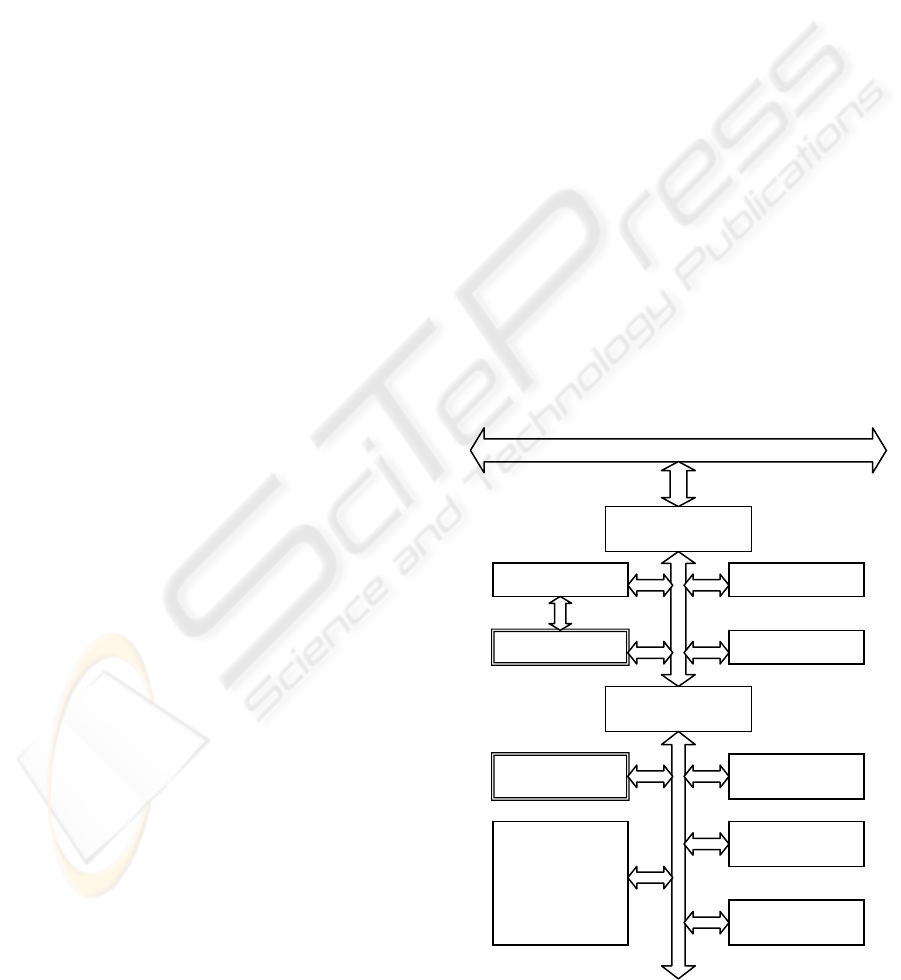
Controller card. The block scheme of this card is
shown in Figure 1.
One ARC card is capable of controlling four
joints. In the Experimental Robot Controller there
are two ARCs, each responsible only for three joints.
Since the hardware build up of the manipulator
provides an Euler configuration wrist, the
partitioning of the first and second three joint
provides further possibility of creating a simpler
control software system.
Starting from the power electronics side, every
ARC cards contains a Texas Instruments
TMS320C31 digital signal processor with four
whole featured interfaces controlling electronic
drives. Together with its interfaces, the high speed
CMOS 32-bit floating point processor has the
following capabilities: taking the position signals
and calculating the speed and acceleration of the
corresponding joints; performing calibration and
credibility checks using null impulses; supervising
the position, speed and acceleration limits;
producing the set point values for the servo
amplifiers; providing synchronous movement
between the joints controlled by a stand alone or by
more ARC cards. The 16 MIPS and 32 MFLOPS
processor has high speed static RAM for the best
possible performance. This processor, using the pre-
programmed boot loader, can boot from the FLASH
memory or from the dual port RAM. The second
method can be well used for development and test.
Additionally to the drive interfaces, there is a three-
wire synchronization channel built in. With the help
of this feature more ARC cards are capable of acting
together and coordinating multi drive systems.
The next part of the ARC card is the so called
pre-processing unit. It is based on an Intel 80386EX
microprocessor. This embedded processor is fully
compatible with the PC environment and has a lot of
integrated peripherals supporting the rich
functionality. This unit can boot from the attached
FLASH memory and connected to the signal
processor via dual port RAM. On the other side, the
communication between the host computer and the
pre-processing unit goes through the ISA bus and
the dual port RAM. In both directions the handling
of the RAM is fully interrupt driven, in order to
reach the highest possible performance. The
interface could be converted into PCI for even
higher speed, but it would require the complete
redesign of this extension card. However, the ISA
bus interface is the slowest connection in the chain,
it provides enough communication bandwidth for
very complex control tasks.
The central part of the robot controller is the full
featured personal computer. Since the ISA bus
interface is required by the ARC cards, the host CPU
is an Intel Celeron 633MHz processor.
ISA
b
us
Dual Port RAM
4kword
DRAM memory
i80386EX
Flash memory
CAN interface
Dual Port RAM
4kword
SRAM memory
TMS320C31
Incremental
encoders
interface unit
Analog outputs
Digital IOs
Figure 1: The block scheme of the ARC cards.
MULTIPROCESSOR ROBOT CONTROLLER - An Experimental Robot Controller for Force-Torque Control Tasks
541
2.2 The Force Torque Sensor
Interface Card
The most recent hardware addition to the
Experimental Robot Controller is the six-component
force torque sensor. The sensor head is built between
the last joint of the robot and the end effecter. The
sensor is directly connected to its electronics, the so
called MiniForce unit. The tasks of this unit are to
receive the signals from the strain gages, perform
decomposition and produce the results of the
measurement. There is a metal cage in the sensor
head and the voltage of multiple gages is measured
in order to provide the three components force and
torque. The MiniForce unit is attached to the base of
the manipulator. It contains the controlling
electronics of the sensor head and it performs the
analogue-digital conversion, digital signal filtering
and matrix compensation, eliminating the crosstalk
effects. In this configuration the effects of the
electrical noises are the minimal, in the
measurement system as well.
The MiniForce unit is connected through an
RS422 differential line to the force torque sensor
interface card. This is a PCI bus extension card
directly built in the central control computer (Hankó,
2004). This unit contains one additional (to the ARC
cards) Texas Instruments TMS320C32 digital signal
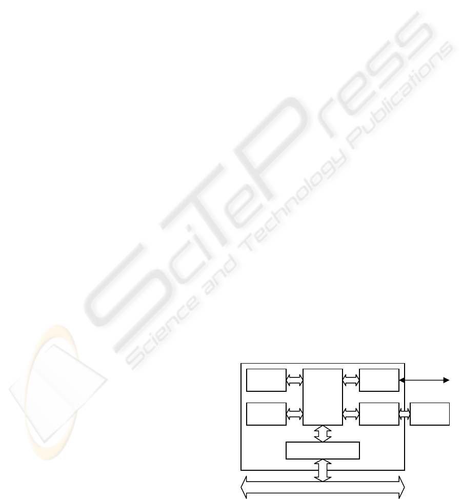
processor. The block scheme of this extension card
is shown in Figure 2. An additional CAN interface is
implemented on the sensor interface card in order to
provide fast and direct communication with the ARC
cards. This channel provides fast and direct
connection, avoiding the additional load on the host
processor (the Intel Celeron processor working on
the motherboard). This communication has limited
bandwidth, but it is enough for exchanging the most
important data.
3 THE SOFTWARE SYSTEM
In this section the whole software system of this
multiprocessor control system is presented. Starting
from the manipulator side, in the first line there are
the digital signal processors (DSPs).
3.1 The Software of the Extension
Cards
The manufacturer of this processor provides
assembler, optimizing ANSI C compiler and linker
for these devices. Every DSP environment is capable
to start automatically from the provided FLASH
memory. During the software development and test
phase the DSPs can be started from the connected
dual port RAMs by the host processor in the case of
the sensor interface card or by the communication
processor in the case of the ARC cards. This dual
boot functionality is supported by the boot loader
integrated in the processor and can be configured by
jumpers on the corresponding extension card.
The next operational unit is the communication
processor with its environment on the ARC cards. In
the current version the i80386EX processors
perform only data relay between the host processor
and the joint processors (the DSPs on the ARC
cards). The necessary computational power is
provided by the other parts of the system. As
mentioned above, the host system runs QNX
operating system and there is ongoing development
for embedding the QNX into the communication
processors. In order to embed the QNX operating
system, some additional BIOS functionality must be
implemented. These are required for initializing the
environment and starting the Initial Program Loader
(IPL). The duty of IPL is to load the compressed
operating system image, decompressing it in the
memory, switching into protected mode and starting
the QNX. With the help of this environment there
will be hopefully more resources available, while the
efficiency of the communication can be maintained.
3.2 The Software of the Central
Control Computer
The host computer is a full featured workstation.
Since the early times of this research and
development project the QNX operating system is
used on the central computer. This operating system
is a real-time Unix-like one, developed especially
PCI
b
us
SRAM
Flash
DSP
CAN
interface
RS422
interface
Dual Port RAM
Miniforce
Sensor
interface
card
Figure 2: The force-torque sensor interface card.
ICINCO 2006 - ROBOTICS AND AUTOMATION
542
for time critical process control task. The previous
version (QNX v4) contained a lot of special features
focusing on the primary aim, the very good real-time
performance. In those times the robot control
software system was very complex, containing more
than ten separate, but heavily communicating
processes.
Recently the whole software system was ported
under the new version of the operating system, the
so called QNX Neutrino. This is the 6
th
version (the
5
th
was omitted by the developer) and the whole
software suite is called QNX Momentics. It contains
not only the core operating system and numerous
supporting utilities, but a graphical user interface
(GUI) called Photon and a full featured development
environment as well.
Both versions of the operating system have
microkernel based architecture. The small central
kernel provides only the most important services
such as pre-emptive scheduling, status handling and
the basic communication services. A whole desktop
environment is slower in a microkernel architecture
system, but the system builders and software
developers have the ability to build a reduced,
efficient, very fast environment. This aim is
supported by the modularity and the fine tuneable
scheduling mechanism. The most important change
between the mentioned versions is that the process
based scheduling changed to a thread based one.
Another significant change is made in the
philosophy, and instead of using vendor specific
methods, the solutions according to the POSIX
standard are implemented.
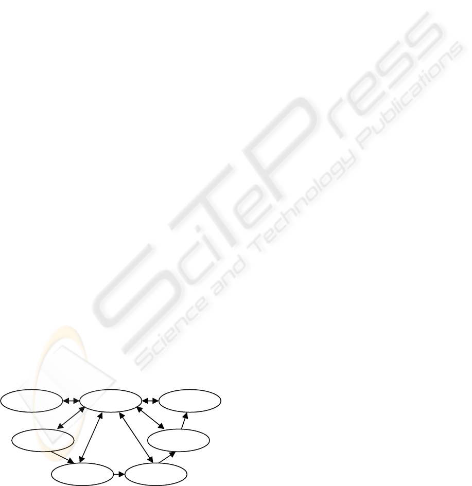
Following the evolution, the whole robot control
software was rewritten last year according to the
new operating system version. The process structure
of the new robot control software is shown in Figure
3. The original robot plant used the Advanced Robot
Programming System (ARPS) as the robot
programming language. This environment was
implemented using the own developed robot
controller as well. Since the scheduling is now based
on the threads instead of processes, the structure is
quite simple. The last process, the one responsible
for MiniForce communication, is the most recent
software development. It was written and fitted in a
few months later than the software relocation took
place.
The participants of this research and
development project at the Department of
Automation and Applied Informatics have important
achievements. The most important outcome is the
integration of the sensor system and the start of the
software implementation of various methods based
on the capabilities of the hardware. However, there
is a lot of work to be done in the field of modern
robot control systems.
ACKNOWLEDGEMENTS
The project of studying modern robot control
algorithms and their realization in a real
environment is supported by Hungarian Research
Found (OTKA, grant No. T029072, grant No.
T042634).
REFERENCES
Tevesz, G., Bézi, I. And Oláh, I., 1997. A Low-cost Robot
Controller and its Software Problems. In Periodica
Polytechnica Ser. El. Eng. Vol. 41, No. 3., pp. 239-
249
Hankó, T., 2004. Hatkomponensű erő-nyomatékérzékelő
illesztése PCI buszra. (A PCI bus interface for six
component force torque sensor.) Diploma work, in
Hungarian, Department of Automation and Applied
Informatics, Budapest University of Technology and
Economics
Oláh, I., Tevesz, G., 2002. Software Problems of an
Experimental Robot Controller Based on QNX Real-
Time Operating System. In Periodica Polytechnica
Ser. El. Eng. Vol. 46, No. 3-4., pp. 151-161
Oláh, I., Tevesz, G., 2005. An Experimental Robot
Controller for Force-Torque Control Tasks. The
International Journal of INGENIUM 2005 (4) –
Engineering Achievements Across the Global Village,
edited by Janusz SZPYTKO, Cracow-Glasgow-
Radom, pp. 477-484
Figure 3: The process structure.
Kernel Init
Pendant
Interprete
r
Pathgen
Control
MFCom
m
MULTIPROCESSOR ROBOT CONTROLLER - An Experimental Robot Controller for Force-Torque Control Tasks
543
