A HYBRID FEEDBACK CONTROLLER
FOR CAR-LIKE ROBOTS
Combining Reactive Obstacle Avoidance and Global Replanning
Matthias Hentschel, Oliver Wulf, Bernardo Wagner
Institute for Systems Engineering
University of Hannover
Hannover, Germany
Keywords: Autonomous mobile robots, motion planning, obstacle avoidance, AGV system.
Abstract: This paper presents a hybrid feedback controller for path control of autonomous mobile robots. The
controller combines reactive obstacle avoidance with global path replanning, enabling collision-free
navigation along a preplanned path. Avoidance of local obstacles is accomplished by adjusting the vehicle’s
lateral deviation from the path trajectory reactively. Global path replanning is performed to circumvent
obstacles which cannot be avoided locally. In contrast to common approaches, this is done by searching an
optimal path returning to the initial trajectory beyond the obstacle. Following the description of the hybrid
feedback controller, experimental results will demonstrate the effectiveness of this approach.
1 INTRODUCTION
In the last few years remarkable progress in the
localization of autonomous mobile robots has been
achieved. Especially the Monte Carlo Localization
(Daellert et al., 1999) (Wulf et al., 2005) has to be
mentioned as a robust and reliable method for global
position estimation. The precise localization enables
exact navigation of autonomous vehicles along a
preplanned trajectory. This is a key requirement for
autonomous mobile robots and Automated Guided
Vehicle (AGV) systems. This kind of vehicles, e.g.
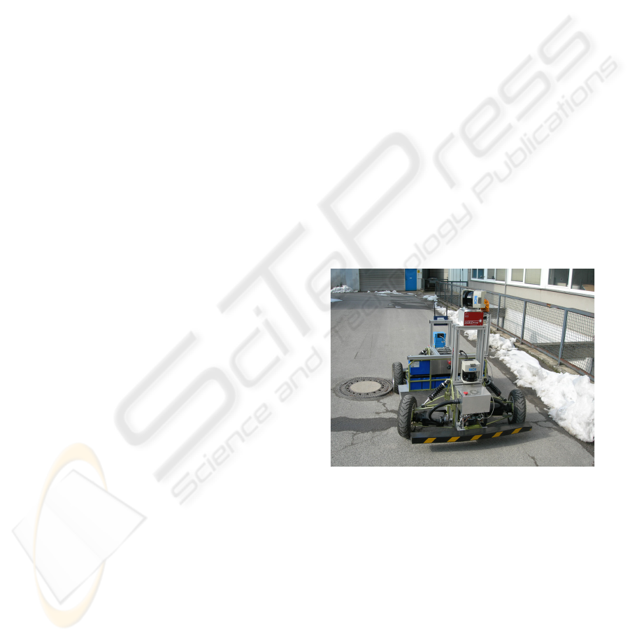
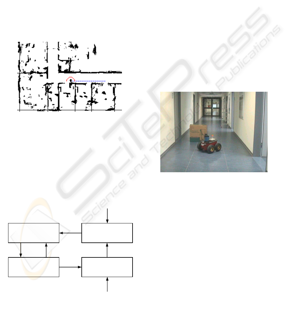
our autonomous robot RTS-DORA (see Fig.1) and
our RTS-STILL Robotic Fork Lift typically serve in
industrial environment. In these surroundings robots
have to deal with fixed ways and storage places as
well as prestructured production processes. By
applying the predefined trajectories, a deterministic
behaviour of the autonomous robot is achieved.
Nevertheless, collision avoidance is a key challenge
in these applications, especially if mobile robots and
human beings share a common workspace. People
and other dynamic obstacles block the robot’s path
hence making it necessary for the autonomous
system to perceive the environment and react
dynamically to unforeseen circumstances.
Principally collision avoidance methods for
mobile robots can be divided into global and local
approaches. The global techniques, like road-map,
cell decomposition and potential field methods
(Latombe, 1991) (LaValle, 2006), assume that a
complete model of the robot’s workspace is
available. Generally the global world models are
based on sensory input and can be updated by using
probabilistic representations (Moravec, 1988). Due
to the knowledge about the global obstacle situation,
these collision avoidance methods enable global
path planning. A complete path from a starting point
Figure 1: Autonomous mobile robot RTS-DORA.
445
Hentschel M., Wulf O. and Wagner B. (2006).
A HYBRID FEEDBACK CONTROLLER FOR CAR-LIKE ROBOTS - Combining Reactive Obstacle Avoidance and Global Replanning.
In Proceedings of the Third International Conference on Informatics in Control, Automation and Robotics, pages 445-450
DOI: 10.5220/0001215604450450
Copyright
c
SciTePress
to a goal location can be calculated off-line.
Unfortunately, these global techniques are not
appropriate for fast obstacle avoidance. This is a key
feature of local, or reactive obstacle avoidance
approaches. These methods typically consider only a
small subset of obstacles close to the robot, thus
adapting quickly to unforeseen changes in the
environment. Well known reactive techniques are
force field methods (Borenstein and Koren, 1990)
and the dynamic window approach (Fox et al.,
1997). Because of considering only the nearest
surrounding close to the robot, local approaches can
easily be trapped in local minima such as U-shaped
obstacle configurations.
This paper describes a feedback controller that
combines both local and global obstacle avoidance
techniques. The hybrid controller connects the
preferences of both methods thus enabling collision-
free navigation along a predefined trajectory.
Reactive obstacle avoidance is performed by
adjusting vehicle’s lateral deviation obstacle-
depending to the nominal trajectory. This is fulfilled
in real-time by a straightforward algorithm allowing
high-speed collision avoidance. To give the local
technique the capability of handling path blocking
obstacles (like closed doors) and other local minima,
global path replanning is performed in cases where
obstacles cannot be avoided reactively. Based on an
occupancy grid map updated with laser range data, a
feasible path is searched by Dijkstra’s algorithm
(Dijkstra, 1959). Similar to the well-known A*
algorithm, this method represents the global part of
the controller. In contrast to common approaches,
our algorithm searches an optimal path returning to
the initial trajectory behind the obstacle. Based on
the search result, the initial trajectory is replanned
around the global obstacle. As the recalculation of
the complete path is not necessary, this approach is
especially effective for long trajectories.
2 HYBRID FEEDBACK
CONTROLLER
2.1 Path Tracking
The path which has to be followed by the mobile
robot consists of a concatenation of i lines and polar
splines (Horn, 1997). From a set of predefined
waypoints, this trajectory is generated automatically
by our motion planner with regards to the kinematic
constraints of the vehicle. Additionally for each path
segment a desired speed and driving direction is pre-
selectable. With cusps allowed in path trajectory, a
robot model similar to Reeds-Shepp’s car (Reeds
and Shepp, 1990) is assumed. Due to the
consideration of robot’s nonholonomic constraints in
path generation each planned trajectory is driveable
in general.
Trajectory tracking is performed by a cascade
controller, combining feedforward and feedback
control for high path accuracy. Figure 2 illustrates
the significant parameters used in position control.
The longitudinal position of the robot R on a single
path element P is denoted as
(P)
L
R
in reference to the
local coordinate system S
P
of that segment. The
transversal displacement
(P)
T
R
is normal to the path P
(with C
P
as the perpendicular foot) and is defined as
the distance between the robot position (coordinate
system S
R
) and the trajectory. The orientation error
(P)
φ
R
is the difference between the slope of the
tangent-line through the point C
P
and the robot
orientation
φ
R
.
With a given position and orientation of the
mobile vehicle in the initial coordinate system S
W
,
the parameters
(P)
L
R
,
(P)
T
R
and
(P)
φ
R
can be calculated
Figure 2: Robot location on a single path segment P.
R
x
RP T)(
RP
L)(
P
y
P
x
R
y
R
φ
W
x
W
y
RS
PS
WS
path segment P
robot R
•
PC
s
Figure 3: Overview of the closed-loop control system for
path tracking.
feed forward
control
RP L)(
RP
φ
)(
RP T)(
P
refRP T ,)(
+
−
R
r
robot R,
localization
feed back
control
+
+
ICINCO 2006 - ROBOTICS AND AUTOMATION
446
and used for path control. A fundamental overview
of the closed-loop control system is provided by
Figure 3. Output of the position controller is defined
as r
R
, the radius of the curvature which shall be
driven by the robot. Within the vehicle’s chassis,
this set value is transferred into steering commands.
The reference input of the position controller is
denoted as
(P)
T
R,ref
. For path tracking in the absence
of obstacles this parameter will be
(P)
T
R,ref
=0, thus
enabling precise piloting of the autonomous robot
along the planned path.
2.2 Local Obstacle Avoidance
The reactive obstacle avoidance has to provide a
path that circumnavigates obstacles in the local
surrounding of the robot. Moreover the transition of
narrow corridors and tight doors must be possible
even with noisy localization. Koren and Borenstein
(1991) discovered that the commonly used potential
field methods (PFM) often fail between closely
spaced obstacles and tend to oscillate in narrow
corridors. Above all, PFMs and other reactive
techniques like the dynamic window approach are
designed for guiding a vehicle safely to a single goal
location. However, obstacle avoidance along a well-
defined trajectory is hard to realize.
In this work we use a straightforward algorithm for
reactive obstacle avoidance. This approach adjusts
the reference input
(P)
T
R,ref
(see Fig. 3) of the position
controller obstacle-depending, admitting a control-
lable lateral displacement of the vehicle from the
trajectory. With regard to the kinematic constraints
of the robot, the deviation of the vehicle is adjusted
by the position controller as quickly as possible to
(P)
T
R,ref
.
The lateral displacement
(P)
T
R,ref
is computed from
the sensory input of at least one laser sensor. As we
use the planar world assumption, each scan consists
of a list of k two-dimensional obstacle points in
Cartesian coordinates D
n
=(x
n
,y
n
) with n being the
index. All measurements are received in robot
coordinates S
R
. The first step in assessing
(P)
T
R,ref
for
a single path segment is a transformation of all k
measurement points D
n
into the coordinate system S
P
of the local path element P. The resulting points
(P)
D
n
are given by:
()
PR
PP
PP
nnP SSDCD −
⎟
⎟
⎠
⎞
⎜
⎜
⎝
⎛
−
+⋅=
)cos()sin(
)sin()cos(
)(
φφ
φφ
(1)
with
where
φ
P
is the orientation of the path element’s
coordinate system S
P
in initial coordinates S
W
. Next,
for each of the l points
(P)
D
n
(with l
⊆
k), that are
normal to the local path element P the longitudinal
position
(P)
L
Dn
as well as the transversal dis-
placement
(P)
T
Dn
is determined. The result is
illustrated by Figure 4.
LDnPi)(
The obstacle points which interfere at most with
the robot are those closest to the trajectory. With the
transformation of the sensor data onto the path, a
simple determination of these two points
(P)
O
l
and
(P)
O
r
(see Fig. 4) is possible. According to the
following equation, they are defined by:
()
⎟
⎟
⎠
⎞
⎜
⎜
⎝
⎛
=
n
n
DP
DP
lP
T
L
O
)(
)(
)(
max
ln
T
nDP
<≤
<
≤
∞
−
0
,0
)(
(2)
()
⎟
⎟
⎠
⎞
⎜
⎜
⎝
⎛
=
n
n
DP
DP
rP
T
L
O
)(
)(
)(
min
ln
T
nDP
<≤
∞
≤
≤
0
,0
)(
To interfere with the path tracking of the
autonomous robot, at least one of the obstacle points
(P)
O
l
and
(P)
O
r
must be in the driveway of the
vehicle. The width of this area is described by:
SR www
+
=
(3)
Figure 4: Sensor data (red) in robot coordinates S
R
(left)
and in transformed coordinates of the local path segment
P (right).
R
x
Ry
RS
P
x
Py
PS
P
P
transformation
nDP L)(
nDP T)(
rP
O)(
lP O)(
⎟
⎟
⎠
⎞
⎜
⎜
⎝
⎛
+−
−+
=
)sin()sin()cos()cos()sin()cos()cos()sin(
)cos()sin()sin()cos()sin()sin()cos()cos(
PRPRPRPR
PRPRPRPR
C
φφφφφφφφ
φφφφφφφφ
A HYBRID FEEDBACK CONTROLLER FOR CAR-LIKE ROBOTS - Combining Reactive Obstacle Avoidance and
Global Replanning
447
where w
R
is the width of the (symmetric) robot. The
parameter w
S
specifies the upper bound of an
additional safety margin. If sufficient free space is
available, this distance is to maintain to obstacles.
Unless enough space for w
S
is present, e.g. in narrow
corridors, the safety margin may be reduced
dynamically down to zero.
With the size of the driveway w, the lateral
displacement
(P)
T
R,ref
is finally computed as follows:
0,)( =refRP T
,
2
,)(
w
O
TlP −≤
2
,)(
w
O
TrP ≥
(4)
2
,)(,)(
,)(
TlPTrP
refRP
OO
T
+
=
(5)
,
2
,
2
,)(
,)(
R
TlP
TlP
w
O
w
O
−≤
−>
.
2
2
,)(
,)(
w
O
w
O
TrP
R
TrP
<
≥
refRPrefRP TT ,)(,)( =
,
2
,)(
R
TlP
w
O
−>
(6)
2
,)(
R
TrP
w
O
<
In equation 4, the obstacle points
(P)
O
l
and
(P)
O
r
are both outside the driveway, hence not interfering
with the robot. The reference input
(P)
T
R,ref
is set to
zero. In cases where a single obstacle point is inside
the driveway (equation 5), the reference value is
defined as the average between
(P)
O
l,T
and
(P)
O
r,T
.
This permits the transition of narrow corridors and
tight doors. Additionally, the lateral displacement
(P)
T
R,ref
is adjusted in dependence of the available
free space and limited in its maximum value.
Equation 6 defines the limitation of the local
obstacle avoidance. In cases both obstacle points are
located within an area of the vehicle’s width on the
trajectory, these (continuous) obstacles are
reactively unavoidable.
2.3 Global Path Replanning
The global part of the hybrid feedback controller
performs replanning of the original trajectory in case
an obstacle situation cannot be avoided locally. As
described above, this occurs e.g. if the whole
driveway is blocked by an obstacle. In order to
replan the original trajectory, an admissible path
around the global obstacle is searched. This is
achieved by a discrete feasible path planner. For
this, the essential knowledge about the global
obstacle situation is represented as a sensory updated
occupancy grid map (Moravec, 1988) as shown in
Figure 5. With the grid cells of this map a nonempty
state space X is defined.
For path planning, the initial state x
I
∈
X is given
by the robot’s position S
R
in front of the global
obstacle. From this location the searched path must
return to the trajectory behind the obstacle as fast as
possible. Differing from common approaches, this
requires a set of well-defined goal states X
G
⊆
X.
Each goal state is part of a section (with the length
d) from the original trajectory behind the global
obstacle.
With a given x
I
and X
G
, the searching for the
feasible path is performed by Dijkstra’s algorithm
(Dijkstra, 1959). This method discovers the single-
source shortest path in a directed graph. The
associated costs l(e) for applying each edge e of this
graph are deduced from the grid map obstacle-
depending (see Fig. 6).
Searching for an cost-efficient path is terminated,
when a goal state x
G
⊆
X
G
is reached by Dijkstra’s
algorithm. The states of the resulting path between x
I
and a x
G
are denoted as X
P
⊆
X. By applying various
filter techniques, the number of path states X
P
can be
reduced to a rudimental set of states X
W
⊆
X
P
. These
states X
W
define the vertices of a polygon which
represent the optimal path.
Figure 5: Exemplary occupancy grid map.
Figure 6: Cost function deduced form the grid map.
ICINCO 2006 - ROBOTICS AND AUTOMATION
448
With the reduced states X
W
, finally replanning of
the original trajectory is enabled. Transformed into
global waypoints, the set X
W
is assigned to our
motion planner. Similar to the generation of the
original trajectory from a group of given basepoints,
the motion planner creates a trajectory with the
computed waypoints. Starting from the current robot
position, this trajectory permits circumnavigation of
the global obstacle and returns to the original
planned path behind the obstruction. Here, the newly
generated trajectory is concatenated to the original
one with a constant transition. As a result, the entire
replanned trajectory is available. Due to considering
robot’s nonholonomic constraints in path generation,
this trajectory is driveable in general.
By searching a cost-optimal path returning to the
original trajectory, only a small fraction of the grid
map has to be considered for path replanning (see
Fig. 7). As recalculation of the complete path is not
required, the computational complexity of this
approach remains low.
Finally, a brief overview of the hybrid feedback
controller presented in this paper is summarized by
Figure 8:
3 EXPERIMENTAL RESULTS
Under real-world condition, the described feedback
controller is tested on different robot platform in
indoor and outdoor environment.
The experimental results presented here are made
exemplary in a real world environment at our
institute. With a size of 50m x 20m, the test
environment includes doors, narrow corridors and
unforeseen obstacles. In this environment the robot
is driven fully autonomous along a preplanned path
with a maximum speed of 0,8 m/s. For the reactive
obstacle avoidance, a maximum lateral displacement
of ± 0,45 m is permitted.
The experimental robot consists of an ActivMedia
Pioneer2 based platform (0,5m x 0,5m), equipped
with an 2D Ibeo LD-A 360° laser range sensor. Data
acquisition and all required algorithms for the hybrid
feedback controller are computed in real-time on an
embedded PC.
The hybrid feedback controller presented in this
paper is used for piloting the robot safely along the
preplanned path. Figure 10 shows the results and the
obstacle configuration from a top view. The blue
line represents the nominal trajectory which is
generated by our motion planner from a set of given
waypoints. Labelled in red, the real path piloted by
the robot is illustrated.
Starting from the point S, the robot firstly
encounters a narrow door (Fig. 10a). As soon as the
obstacle is recognised, the feedback controller
deviates reactively from the original trajectory and
passes through the door exactly centred. Subsequent,
the robot returns to the original trajectory as soon as
it is admitted by the obstacle situation.
Figure 9: Test environment at our institute, lines on the
floor mark the preplanned trajectory.
Figure 7: Replanned path (red) returning to the original
trajectory (blue, dashed).
Figure 8: Hybrid feedback controller.
local
obstacle-avoidance
global
path replanning
path
tracking
trajectory
generation
start:
g
lobal wa
yp
oints
occu
p
anc
y
g
rid ma
p
obstacle
reactively
unavoidable
computed
basepoints
refRP T ,)(
i path
segments
current path
segment P
A HYBRID FEEDBACK CONTROLLER FOR CAR-LIKE ROBOTS - Combining Reactive Obstacle Avoidance and
Global Replanning
449
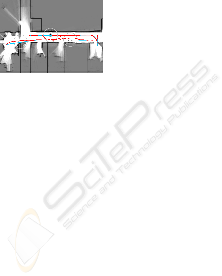
Next, precise path tracking is performed, until the
ladder (Fig. 10b) is identified as an obstacle and
avoided locally. In contrast to the previous door
transition, sufficient free space is available to
maintain the safety margin to the obstacle.
After another door passage while reversing, the
mobile robot encounters a global obstacle on its way
back (Fig. 9, 10c). This obstacle is reactively
unavoidable. In this case, global path replanning is
performed by the hybrid feedback controller to
circumvent the situation. In Figure 10, the replanned
trajectory is illustrated by a dashed line. Using the
hybrid feedback controller, this updated trajectory is
followed by the robot until the point G is reached.
Further evaluation of the hybrid feedback
controller has been performed using our mobile
robot RTS-DORA (see Fig.1). With a total weight of
350 kg and a size of 2,3m x 1,34m the maximal
lateral displacement for local avoidance is set to
±1,0 m. Numerous test runs have been performed on
this robot with speeds of up to 2 m/s. These
experiments show that our approach can be used for
different kinds of vehicles and is not depending on
the platform size and speed.
4 CONCLUSION
In this paper we presented a feedback controller for
autonomous car-like robots. This controller enables
collision-free tracking of a preplanned trajectory. In
our approach, the controller combines reactive
obstacle avoidance with global path replanning. The
experimental results have shown that the
combination of both local and global obstacle
avoidance techniques leads to a robust and efficient
path controller. Over all, our hybrid feedback
controller is capable of piloting safely different
mobile robots along preplanned paths in indoor and
outdoor environment. With tested speeds up to 2
m/s, the circumnavigation of multiple unexpected
obstacles is possible. Next to the prevention of
obstacles, our approach enables the transition of
narrow corridors and tight doors as well.
REFERENCES
Borenstein, J. and Koren, Y., 1990, Real-time obstacle
avoidance for fast mobile robots in cluttered
environments, ICRA ’90, International Conference on
Robotics and Automation.
Dellaert, F., Fox, D., Burgard, W. and Thrun, S., 1999,
Monte carlo localization for mobile robots, ICRA ’99,
International Conference on Robotics and
Automation.
Dijkstra, E.W., 1959, A note on two poblems in connexion
with graphs, Numerische Mathematik 1, pp. 269-271.
Fox, D., Burgard, W. and Thrun, S., 1997, The dynamic
window approach to collision avoidance, IEEE
Robotics and Automation Magazin.
Horn, J., 1997, Path control of a mobile robot based on
absolute localization by fusion range image and dead-
reckoning data, Fortschrittberichte VDI Reihe 8, vol
617.
Latombe, J., 1991, Robot motion planning, Kluwer
Academic Publishers, Boston.
LaValle, S.M., 2006, Planning algorithms, Cambridge
University Press, Cambridge.
Moravec, H.P., 1988, Sensor fusion in certainity grids for
mobile robots, AI Magazine, vol 9, summer 1988, pp.
61-74.
Reeds, J.A. and Shepp, L.A., 1990, Optimal paths for a car
that goes both forwards and backwards, Pacific
Journal of Mathematics, 145(2): 367-393
Koren, Y. and Borenstein, J., 1991, Potential field
methods and their inherent limitations for mobile robot
navigation, ICRA ’91, International Conference on
Robotics and Automation.
Wulf, O., Khallaf-Allah, M. and Wagner, B., 2005. Using
3D data for monte carlo localization in complexe
indoor environments, ECMR ‘05, European
Conference on Mobile Robots.
Figure 10: Occupancy grid map of the test environment,
including preplanned trajectory (blue) and real path
(red).
S
G
b
c
a
ICINCO 2006 - ROBOTICS AND AUTOMATION
450
