
MISSION PLANNING, SIMULATION AND SUPERVISION OF
UNMANNED AERIAL VEHICLE WITH A GIS-BASED
FRAMEWORK
Pedro Gutierrez, Antonio Barrientos, Jaime del Cerro, Rodrigo San Martin
ETSII Universidad Politecnica de Madrid
Jos Gutierrez Abascal 2, E-28002 Spain
Keywords:
Unmanned aerial vehicles, mission planning, geographic information system, supervision.
Abstract:
A framework for mission planning, simulation and supervision of unmanned aerial vehicles (UAV) has been
developed. To provide a rich context for mission planning an Enhanced Reality is created from Geographic
Information System (GIS) sources and dynamic aggregation of available geo-referenced data. The mission
is expressed as statements and expressions of the Aerial Vehicle Control Language (AVCL), the abstraction
mechanism needed to bridge the gap between a strategic mission planner and a heterogenous group of vehicles
and active payloads. The framework is extendable by design and its aimed at the integration of diverse vehicles
with existing systems. It has been tested as a Mission Planning and Simulation tool with our real-time small
helicopter model.
1 INTRODUCTION
The development of UAV platforms usually has fol-
lowed a bottom-up approach where the low-level con-
trol is solved first and the high-level mission planning
last. This is patent in the many articles published in
the past decades on attitude control, modeling and tra-
jectory tracking for UAVs, whereas mission planning
and supervision interfaces and systems received lit-
tle attention. This is a reasonable, even natural, ap-
proach, but more often than not the design of the top
control hierarchy is conditioned by the low-level con-
troller’s capabilities and design-time choices. Fur-
thermore, outside military-related research (of the
Secretary of Defense, 2005) there is no driving force
for the use of applicable standards and technologies
to ease integration of heterogeneous vehicles with ex-
isting systems.
Our university has three functional autonomous
aerial vehicles, and two more will become operational
in the next few months. Therefore we established a
top-down design for the higher levels of the software
hierarchy. In other words, it is assumed that the sys-
tem will have to accommodate to an heterogeneous
group of UAVs, low and mid-level control capabili-
ties/designs and active payloads. Additionally the de-
sign requires the use of applicable standards whenever
possible and cost-effective. As the framework moves
down and other projects at the university work their
way up, with different vehicles, the adaptability of the
system will be fully tested.
To date we have developed a GIS-based software
tool for mission planning, simulation and real-time
supervision of UAVs (MP-SS). And serving as the
bridge between the strategic planner and different ve-
hicles (simulated or real), there exists the run-time-
interpreted Aerial Vehicle Control Language (AVCL),
which is a move toward device-independent program-
ming tools, comparable to the MDLe (Hristu et al.,
2000). Both the MP-SS and the AVCL interpreter are
part of a framework that establishes a unified and open
platform for the integration of heterogeneous UAV
systems. So far the Mission Planning - Simulation
loops have been tested.
The AVCL is the abstraction layer that allows the
human supervisor to create missions that are vehicle
and payload independent, promoting code reuse. At
the same time the AVCL statements and commands
hide device specific software/hardware, and serve as
mission definition and storage.
1.1 GIS Data as a World Model
Most UAV research has been driven by military goals
(:19, 1999), so many researchers have focused on re-
active systems and unknown-space navigation. Nev-
310
Gutierrez P., Barrientos A., del Cerro J. and San Martin R. (2006).
MISSION PLANNING, SIMULATION AND SUPERVISION OF UNMANNED AERIAL VEHICLE WITH A GIS-BASED FRAMEWORK.
In Proceedings of the Third International Conference on Informatics in Control, Automation and Robotics, pages 310-317
DOI: 10.5220/0001214603100317
Copyright
c
SciTePress
ertheless the DoD states, in its Unmanned Aircraft
Systems (UAS) Roadmap, that autonomous vehicles
must also perform dull missions, which are repetitive
tasks in known territory, and may be carried out by
simpler and more reliable systems. Even highly re-
active designs must consider the fact that few places
where aerial vehicles fly are completely unknown, be-
ing micro UAVs a notable exception.
Official and commercial institutions work everyday
to provide richer, better and more detailed geographic
and topological databases. In developed countries
Geographic Information Systems (GIS) provide full
coverage with great accuracy, and GIS tools are find-
ing their way in robotics as knowledge representation
technologies (Doherty et al., 2000; Doherty, 2004).
Additionally, the role of GIS is crucial for many
mission planning systems (e.g. inspection of power
lines), GIS-based teleoperation interfaces may have
richer virtual environments, and GIS technologies and
standards provide an excellent medium for spatial-
data sharing. An example is the use of USGS’ Digital
Elevation Models (DEM) as a world model for 3D
navigation (Sinopoli et al., 2001).
2 THE MISSION PLANNER’S
(MP) GRAPHICAL INTERFACE
The Mission Planner (MP) is a .NET application de-
veloped in C# that uses ArcObjects (Institute, ) as the
GIS-enabling API. Using this commercial software li-
brary does, for now, tie the MP to the Windows plat-
form. Nevertheless ArcObjects provides unsurpassed
flexibility because many of the world’s GIS databases
can be used without modification. This level of inte-
gration with GIS might be the most notable difference
and, from our point of view, advantage of the MP over
previous planning tools (Barrouil and Lemaire, 1998;
Tso et al., 1999; Kim et al., 2002; Ramos et al., 2003).
It is important to note that the use of standard GIS
databases does not preclude the use of custom world
models (potential fields, octrees, clusters of spheres,
etc.) for specific tasks, such as autonomous path plan-
ning.
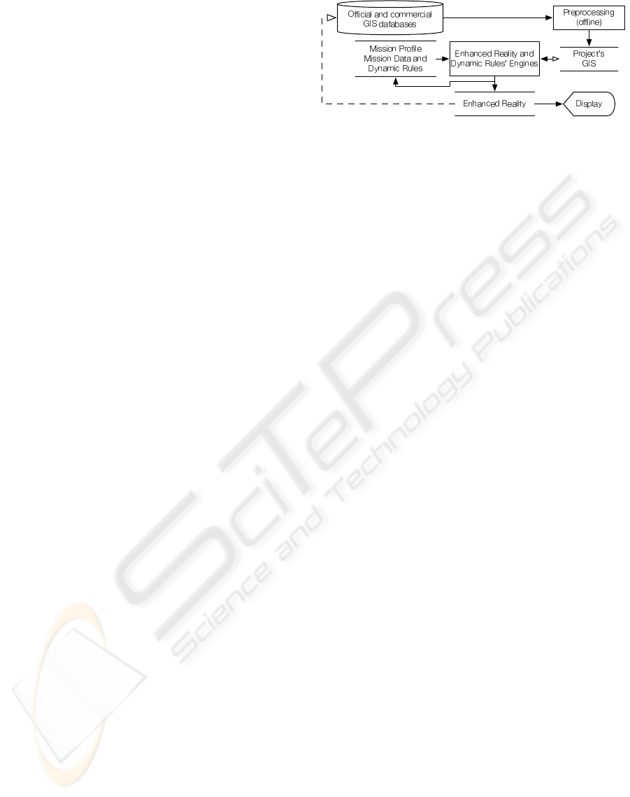
The MP has two interwound tools: one for data
display and other for command input. The former
presents the human operator an Enhanced Reality,
while the latter accepts the vehicle’s commands as
will be explained in Section 3.4. A simplified dia-
gram of the main components of the data display is
shown in Fig. 1, and its relevant aspects are detailed
in the following Sections.
There are several sources of GIS data available
from different levels and institutions of the govern-
ment. Commercial databases are usable too, but they
usually offer less accuracy for unpopulated areas. Ad-
Figure 1: Simplified diagram of the generation of an En-
hanced Reality for Mission Planning, Simulation and Su-
pervision.
ditionally, properly geo-referenced data from various
vehicles’ sensors may be added to the database with
little effort.
Having heterogeneous data sources imposes an of-
fline Preprocessing step: projections, units and co-
ordinate systems are matched; multi-resolution pyra-
mids for efficient display are built for aerial/satellital
photographs; data discrepancies, if any, are solved;
3D representations of bidimensional data are built;
better resolution data is generated by aggregation of
multiple sources; and smaller datasets that match the
mission’s envelope are extracted, and irrelevant data
is discarded. This tasks are handled with GIS tools
(commercial, GNU-licensed, and custom-made) and
usually are one-time jobs.
After Preprocessing the MP software is able to cre-
ate a single file that holds all relevant GIS databases:
the Project’s GIS. This data is static because most GIS
standards can not handle space-time relations (Peu-
quet, 1999), dynamic data is added later. The static
nature of the Project’s GIS is not a limitation because
the main purpose of this database is to serve as the
context of the mission and the starting point at which
the human operator begins to express the mission’s
goals. It may seem at first that a static GIS forces a
deliberative design but this is not the case: fully reac-
tive UAVs may be commanded and simulated in this
virtual environment.
2.1 Mission Profile
It is an XML document that stores the Mission and its
main parameters:
• the location of the Project’s GIS database;
• the different symbols sets for data display. There
usually are many geographic/topological features
available in the Project’s GIS, but not all are rel-
evant at any given time. For example, the loca-
tion of power lines is critical for overhead inspec-
tion missions, so they should be displayed with
high-visibility symbols, while other items should
be subdued or invisible. Different symbol sets are
MISSION PLANNING, SIMULATION AND SUPERVISION OF UNMANNED AERIAL VEHICLE WITH A
GIS-BASED FRAMEWORK
311

arranged as a collection of “layers” whose visibility
can be switched on and off;
• the location of the available Vehicles Libraries (see
Section 3);
• the Mission Data and Dynamic Rules (see Sections
2.2 and 2.3).
The various pieces of the Mission Profile deter-
mine, at run-time and dynamically, how all available
data is presented to the human operator.
2.2 Dynamic Rules
The main application of GIS data in the MP is the
representation of the context in which the mission is
planned -and simulated/supervised in a later stage-
. However, there are restrictions and additional in-
formation that can be inferred or generated both at
design-time and run-time. For example: in most
countries regulations forbid the use of UAVs over
areas with high population densities. The Dynamic
Rules’ engine overlays such areas with the “Forbid-
den” symbology and will disallow any operation of
the UAV within them.
Dynamic Rules do not have to express restrictions,
essentially they are combinations of available data,
provided either by the Project’s GIS, the UAVs or
other Dynamic Rules. They are stored as XML-
snippets that hold three components: its type and pa-
rameters; instructions on how to combine the avail-
able data to create a GIS feature, typically a set of
queries and logical operators; and information on the
way it should be presented in the display and stored
as new GIS data, essentially a set of GIS symbols.
Currently there are 5 types of rules:
• Virtual-data rule: by simple aggregation of exist-
ing GIS data new information can be displayed.
For example, a marker can be created at any loca-
tion where an UAV’s planned trajectory intercepts
a railway.
• Forbidden-zone hard rule: no vehicle can fly within
this zone.
• Forbidden-zone soft rule: creates an interdict that
may be overridden by the human operator.
• Restricted-zone hard rule: a zone that enforces re-
strictions on the UAVs that fly within (e.g. a veloc-
ity limit).
• Restricted-zone soft rule: a zone whose limitations
can be discarded.
It is important to note that a zone in this context is any
valid GIS datatype: point, line, surface or body. As
an example: when a rule creates a forbidden-line no
trajectory may intersect it.
One shortcoming of the Dynamic Rules system is
that they are tied to GIS sources. In other words, if
N government-supplied GIS databases represent free-
ways with M different codes there are two solutions:
to match the codification at the Preprocessing stage,
or to design the rule with all the codes in its defini-
tion. It is important to note that these rules are called
Dynamic for two reasons: data aggregation occurs at
run-time, and dynamic data, such as vehicle’s trajec-
tories, can be aggregated.
2.3 Mission Data
The mission consists of two elements: hotspots
and vehicle commands, both expressed in AVCL.
Hotspots are absolute or relative coordinates of 3D-
points that are relevant to the mission, such as way-
points, the center of an arc trajectory, or a feature that
must be examined with on-board sensors. Features of
the Project’s GIS can not be used directly to define
relative hotspots because it can not be guaranteed that
all UAVs will use the database as an on-board aid to
navigation. If need be the GUI can be used to acquire
the feature’s coordinates before adding the hotspot as
an absolute 3D-point. It is important to note that there
are two exceptions to this rule in the Mission Planning
tool: when a specific UAV “exposes” its capabilities
to the human operator, or when the mission uses mul-
tiple vehicles, but this will be explained later.
In the near future the MP will be extended to in-
clude lines, areas and bodies of interest (LOIs, AOIs
and BOIs, respectively). This will enhance the plan-
ning capabilities because it will be possible to instruct
a vehicle to follow a line without having to define a
large set of hotspots.
As stated above the Mission Data also consists of
vehicle commands. The human operator adds com-
mands to the mission as AVCL statements, either di-
rectly or with the aid of the MP’s GUI. These state-
ments are parsed and interpreted to create a projected
trajectory in real-time (subject to the limitations of
the chosen path-generating algorithm). The trajectory
and additional information (e.g. the number of rev-
olutions in a circular trajectory) are displayed by the
MP and aggregated as applicable GIS datatypes to the
Enhanced Reality. Therefore, this data is available to
most functions of the framework that work with GIS
features.
2.4 Enhanced Reality
The Enhanced Reality is the display of static, dy-
namic, inferred and simulated GIS data. To sum-
marize the previous Sections: the Dynamic Rules’
engine and the Mission Data (mostly hotspots and
trajectories) create GIS features that are aggregated
at run-time to the Project’s GIS to produce the En-
hanced Reality, which is displayed with the symbols
ICINCO 2006 - ROBOTICS AND AUTOMATION
312

sets available in the Mission Profile. A screenshot of
the MP’s GUI is shown in Fig. 2. The MP is able to
show data in 2D and 3D environments, and it has a
global view that provides the context when the user
zooms in. Also available is a Z-profile view, a plot of
altitude vs. distance of both the UAV’s trajectory and
its projection on the ground. The human operator may
change the sizes and relative positions of the different
views to suit the requirements of the current task, but
usually it is easier to plan in 2D and use the 3D-view
only for validation of some mission segments. On the
other hand, simulation normally has opposite require-
ments.
3 THE AERIAL VEHICLE
CONTROL LANGUAGE (AVCL)
So far the use of GIS data and the display of an En-
hanced Reality as contexts/aids to mission planning
have been explained, but the real power of the Mission
Planning framework comes from the use of an Aer-
ial Vehicle Control Language (AVCL) as a vehicle-
independent language to express mission goals and
parameters, UAV and payload commands, and mainly
as an abstraction tool for the management and inte-
gration of an heterogeneous group of aerial vehicles.
Therefore the AVCL should not be regarded as only a
grammar and its interpreter but as a consistent frame-
work.
3.1 The AVCL Grammar and
Interpreter
The AVCL borrows from and extends previous re-
search (Yuan et al., 1999; Dixon et al., 1999; Duarte
and Werger, 2000; Doherty et al., 2000; Kim et al.,
2002; Kim and Yuh, 2003). Because its grammar is
relatively complex it will not be reproduced here in
EBNF. Furthermore, the AVCL is a quasi-imperative
language that loosely follows the design of C++, so
it is fairly simple to grasp its structure by reviewing
its main properties and functionality, and presenting
some code snippets:
• Basic datatypes: bool, double-precision floating-
point number and string.
• Complex datatypes: distance, velocity, time, angle,
angular velocity, angular acceleration, vector/array,
3D-coordinates vector and attitude vector. Both SI
and English units are supported, and an operator for
unit conversion is provided.
• Logical, Comparison and Arithmetic operators
handle all datatypes (e.g. + concatenates strings),
and the interpreter follows the conventions of C++
on operator precedence.
• Trigonometric functions: sin, arcsin, etc..
• Variables, constants and mutables. Variables can be
created/destroyed, and have an associated datatype
while mutables are universal containers.
• Vehicles are stored in variables which point to the
glue-code that represents the simulated/real UAV’s
interfaces, which may be in the computer’s mem-
ory or elsewhere.
• Functions can be overloaded and nested.
• The AVCL follows a soft OOP paradigm, where
all variables are objects with attributes and mem-
ber functions. These can be accessed with the ->
operator, and may in turn be objects (cascaded-
attributes).
• Branches and Loops: if-then-else and while-do in-
structions are supported, with no practical limit to
the depth of the nesting of branches and loops.
The following snippet is valid AVCL code:
# AVLC
variable d, v, x. y, uav
d = 3.33e1 kilometer # a distance var
v = 1.2 fps # a velocity var
x = @0m, 0m, 15m@ # a 3D-point
y = x+@1m, 0m, -4m@ # an offset
uav = loadVehicle[‘‘\libs\moskito.so’’,
params]
uav->TakeOff[4.4ft] # take off to a
given Z
uav->FlyTo[x,4kph,45
o
]# vel/heading
constraints
if (((uav->Sensors)->Camera)->IsOn[])
((uav->Sensors)->Camera)->Snapshots[25,y]
else
print[‘‘ERROR: Camera is OFF’’]
endIf
The AVCL interpreter is a C++ library developed
with the Spirit Framework (de Guzman, ). It has
been successfully compiled for the Windows, Linux
and Mac OS X platforms, both as a dynamically
loaded library and as a standalone application.
The cross-platform design is necessary because the
interpreter resides both inside the Mission Planner
and in any embedded-system that controls an UAV
or active payload. Expressing the vehicle’s operation
with a run-time-interpreted language was a design
goal because it allows to command an UAV with
human-readable short messages, eases integration
with other tools and paves the way for speech-based
interfaces.
It is important to note that, while the AVCL is in-
terpreted at run-time in a sequential manner, the vehi-
cle’s scheduler does not need to be sequential.
MISSION PLANNING, SIMULATION AND SUPERVISION OF UNMANNED AERIAL VEHICLE WITH A
GIS-BASED FRAMEWORK
313
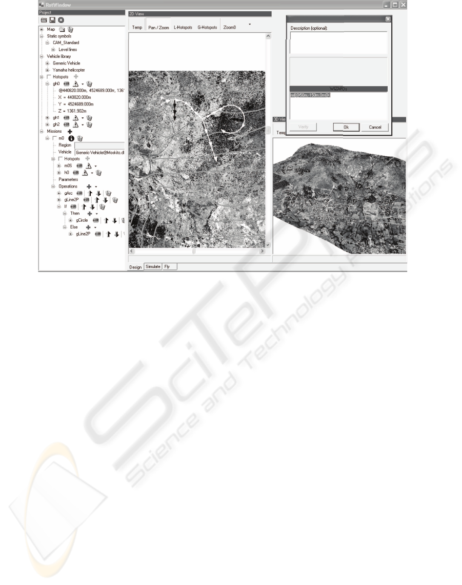
Figure 2: Grayscale screenshot of the Mission Planning GUI with Project Tree, 2D/3D World View and AVCL interface.
3.2 AVCL, the Bridge between
Strategic Planning and Mid-level
Control
As explained above the human operator uses an En-
hanced Reality to plan the mission, which is ex-
pressed by the MP as AVCL statements and expres-
sions. These instructions are converted to trajectories
and associated data by an interpreter, which is either
embedded in the MP or in a simulated/real UAV (see
Fig. 3). This means that for a device to be avail-
able for mission planning it must publish its attributes
and functions as AVCL objects. For UAVs whose in-
terfaces are developed in C++ compatibility with the
AVCL framework is a matter of class inheritance. For
other languages, or for remote objects, glue-code that
complies with the application binary interface (ABI)
of the interpreter is needed. These are not harsh re-
quirements as an AVCL object needs only three at-
tributes:
1. a name;
2. instructions on its use (optional);
3. a list of its attributes/functions, if any;
The attributes are objects themselves, and functions
are in reality two functions that receive the same in-
put parameters: a pointer to the interpreter’s public
state and a vector of the objects that were parsed as
input. The first function exposes the public function’s
state (static parameters), while the second function is
the public function-call per se. Both functions return
a vector of AVCL objects. For example, the FlyTo
member function of an UAV could return, in planning
mode, a vector with the projected waypoints.
Using the AVCL as the bridge between the strategic
planner and the vehicle’s specific hardware/software
has an important advantage: that it too becomes a
bridge between the vehicles. This means that new
connections can be made at run-time, connections that
need not be considered at design-time:
1. a vehicle can be dynamically connected to a “navi-
gator” object with N different algorithms;
2. different active payloads can be freely mixed with
various vehicles, making possible the operation of
the payload capabilities or controlling the vehicle
with the payload:
# the vehicle controls the payload
uav->FlyTo[P1]
while (uav->Position != P1)
camera->Snapshot[P2] # take a picture
of P2
endWhile
# the payload controls the vehicle
uav->FlyUntil[northwest,
thermo->threshold[25]]
ICINCO 2006 - ROBOTICS AND AUTOMATION
314
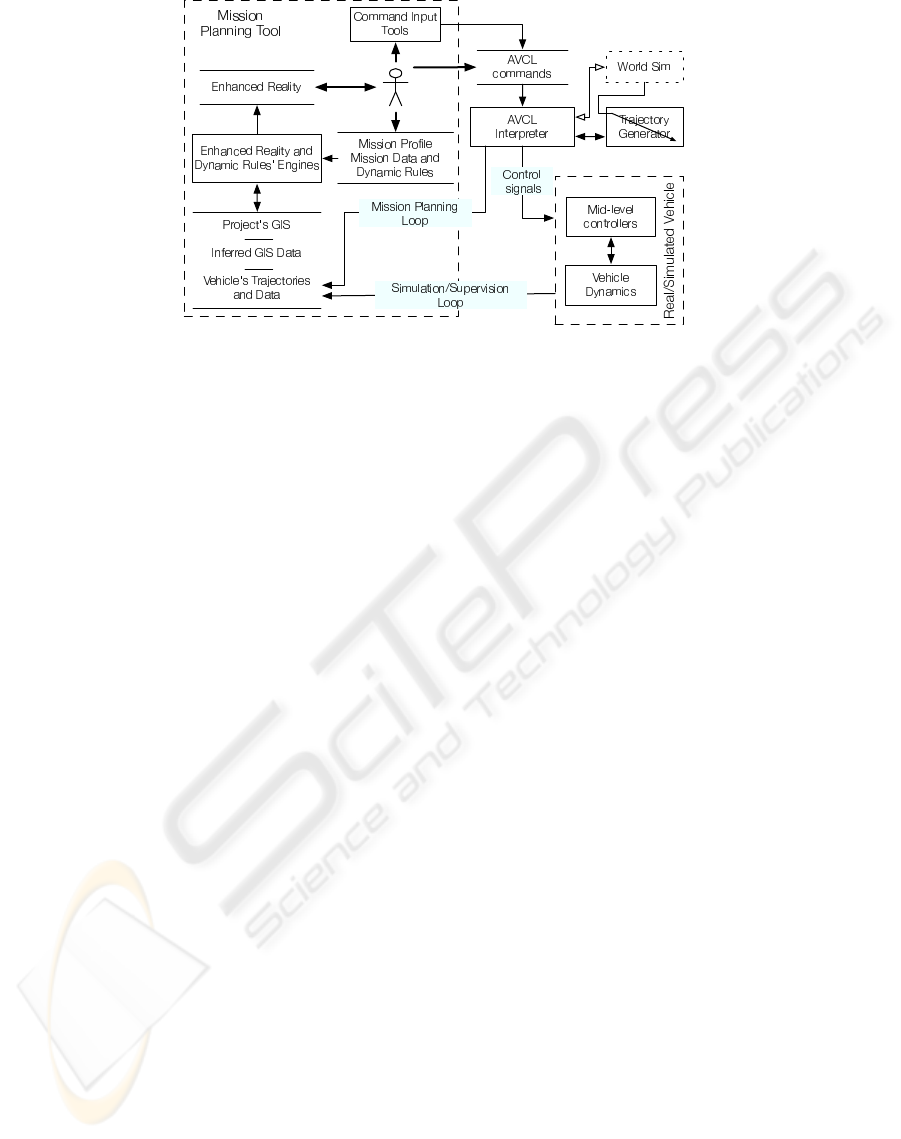
Figure 3: Simplified diagram of the Mission Planning and Simulation Loops.
3. the relation between vehicles and sensors can be
further abstracted:
if (uav->Name == ‘‘RMAX’’)
# function pointer
sense = cam->takePicture
params = { } # empty vector
else
# function pointer
sense = IRcam->takeVideo
params = 10.24s
endIf
uav->FlyTo[P1]
sense[params]
4. simple multi-vehicle missions and behaviors are
possible: uav1->Follow[uav2];
These are just a few simple examples of the possi-
bilities that the AVCL framework opens.
3.3 Generic Unmanned Aerial
Vehicles
The Mission Planner is not tied to a particular set of
vehicles, sensors or commands. At any given time
new functionality can be loaded and displayed to the
human operator as new options and commands. This
means that the MP-SS tool is to be extended through
Vehicle and Command Libraries without recompiling,
and that new capabilities and better vehicles can be
added effortlessly. The Mission Planner is a great
tool for simulation and direct comparison of differ-
ent trajectory trackers, UAV models and controllers,
because it can display N missions at the same time.
The concept of Vehicle Libraries has also been used
to define Generic UAVs. These are baseline vehi-
cles whose capabilities are nonspecific and only true
for a given set of vehicles. The MP-SS tool always
has one such Generic vehicle available: the simplest
UAV, which is capable of the following operations:
arc, change heading, circle, hover, land, two-point
line and take-off. It has no sensors and its trajectory
generator is very simple, it just verifies that the vehi-
cle will not crash with the ground. The “hover” com-
mand is considered generic because it is available for
two of the three more common aerial vehicles (heli-
copter, airship and airplane) and it is a frequent oper-
ation for many missions (e.g. surveillance, data gath-
ering, etc.). Furthermore, it can be “approximated”
by flying in circles, a solution that the MP proposes
when a vehicle not capable of hovering is selected to
fly a mission created with this Generic UAV.
The use of Generic UAVs allows the human oper-
ator to plan missions that are flyable by any vehicle
of a given set. Choosing a Generic vehicle in the MP
means that the operator will design and simulate an
approximation of the mission. After some rough vali-
dations have been made the human operator is free to
choose which vehicle will fly. Obviously the mission
profile must be validated when changing the vehicle
because some parameters might be incompatible (e.g.
velocity and range constraints), but a good Generic
vehicle would ease this task.
Moreover, a large set of generic missions is a good
benchmarking tool for our growing collection of ve-
hicles, models and controllers.
3.4 Planning a Mission
Planning a mission with the MP-SS software tool is a
simple task. The first step is to load the Project’s GIS,
thus setting the context of the mission. Additional op-
erations do not follow a specific order, most of them
are available all the time.
MISSION PLANNING, SIMULATION AND SUPERVISION OF UNMANNED AERIAL VEHICLE WITH A
GIS-BASED FRAMEWORK
315

• Change the project’s profile. Select the available
symbols sets, dynamic rules, etc.
• Add a global hotspot. These are available in all the
project’s missions and for all vehicles.
• Add missions. For each new mission the software
will automatically add a hotspot with random coor-
dinates, the assumed vehicle’s initial position.
• Change the Mission Profile. Select the way the
Enhanced Reality should be displayed (symbols,
views, dynamic rules, etc.).
• Explore the Enhanced Reality. Zoom in and out,
change the on-screen size of different views, etc..
• Add vehicle libraries. These are loaded and the new
functionality is displayed when entering AVCL
commands.
• Add vehicle commands. Because the functions
might be overloaded some parameters are optional
and the type and order defines the outcome.
• Change the vehicle for each mission. The software
will have to validate the mission, and if changing
from a more capable vehicle, conflicts will have to
be manually resolved.
• Save the Mission Profile as an XML document.
• Export the mission commands as a text file. This
file is uploaded to the vehicle to fly the mission.
3.5 The Mission Simulator and
Supervisor
As shown in Fig. 3 the Mission Planner has
two similar loops for mission planning and simula-
tion/supervision. The difference is that in the Plan-
ning Loop the interpreter sends the projected way-
points back to the MP’s Enhanced Reality, while in
the Simulation Loop the interpreter commands the
simulated vehicle, which in turn sends the simulated
positions to the MP. Our research group has devel-
oped a Simulink-based model of a small helicopter
(del Cerro et al., 2004), that includes a position con-
troller and is capable of real-time simulation. This
simulator has been used with the MP-SS tool to test
the Simulation loop. For Mission Supervision the
AVCL commands would be sent to the real vehicle,
and its position plotted alongside the projected and/or
simulated paths.
4 CONCLUSION
A working version of the Mission Planning and Sim-
ulation (MP-SS) tool is available for use with any
UAV, and has been tested with our real-time heli-
copter model for mission planning and simulation. In
the near future the Supervision tool will be evaluated
with our working UAV once the interpreter is engi-
neered into and tested with the embedded platform.
And in the coming months the framework will be in-
tegrated with an heterogenous group of vehicles and
payloads, testing its ability to adapt to different capa-
bilities and design paradigms.
An UAV is only as useful as its payload, thus the
ability of the AVCL-based framework to mix vehicles
and payloads at run-time and without recompiling is
a major advantage when compared to other mission
planning tools. Furthermore, more capable UAVs
can publish mechanisms for the development of new
behaviors using only AVCL commands and expres-
sions. Another benefit of the framework and software
tools is the use of GIS data as the main representation
model for the world. Numerous official and commer-
cial sources can be used to build an Enhanced Reality
for Mission Planning, and there exists a mechanism
for data aggregation and sharing.
4.1 Future Work
The tools described here are operational, but the
framework can (and will) be extended to provide new
functionality or more advanced versions of current
tools. However, there are known limitations. At the
moment the Dynamic Rules’ engine is very simple
and incapable of smart aggregation of GIS data. AI
algorithms would greatly enhance the options for in-
ferring new GIS data. For example the risk of turbu-
lence could be modeled as a function of the 3D terrain
model and land-use information, and this information
used as a new type of rule: a risk zone.
Another limitation is visible in Fig. 3: the World
Sim is, at the moment, just a placeholder for an engine
that will generate additional data for simulation pur-
poses. An example of this would be wind conditions,
GPS-signal quality degradation, virtual sensors or
markers, an many other variables that would greatly
enhance the simulating capabilities of the framework.
The World Sim will be controlled with AVCL com-
mands and will change the parameters of both the in-
terpreter and trajectory generation engines.
In the short term the GUI must be extended to han-
dle all the capabilities of the AVCL framework. No-
tably absent is the operation of sensors not loaded as
vehicle’s attributes but as independent objects. This is
possible with the interpreter but not with the Mission
Planner interface.
ACKNOWLEDGEMENTS
The authors would like to thank CONACYT for their
financial support.
ICINCO 2006 - ROBOTICS AND AUTOMATION
316

REFERENCES
(1999). Civilian applications: the challenges facing the
UAV industry.
Barrouil, C. and Lemaire, J. (1998). An integrated navi-
gation system for a long range auv. In OCEANS ’98
Conference Proceedings, volume 1, pages 331 –335
vol.1.
de Guzman, J. Spirit framework.
del Cerro, J., Valero, J., Vidal, J., and Barrientos, A. (2004).
Modeling and identification of a small unmanned he-
licopter. In World Automation Congress.
Dixon, K., Dolan, J., Huang, W., Paredis, C., and Khosla,
P. (1999). Rave: a real and virtual environment for
multiple mobile robot systems. In Intelligent Ro-
bots and Systems, 1999. IROS ’99. Proceedings. 1999
IEEE/RSJ International Conference on, volume 3,
pages 1360 –1367 vol.3.
Doherty, P. (2004). Advanced research with autonomous
unmanned aerial vehicles. In 9th International Con-
ference on Principles of Knowledge Representation
and Reasoning KR2004, Proceedings of.
Doherty, P., Granlund, G., Kuchcinski, K., Sandewall, E.,
Nordberg, K., Skarman, E., and Wiklund, J. (2000).
The WITAS unmanned aerial vehicle project. In Horn,
W., editor, ECAI 2000. Proceedings of the 14th Euro-
pean Conference on Artificial Intelligence, pages 747–
755, Berlin.
Duarte, C. N. and Werger, B. B. (2000). Defining a common
control language for multiple autonomous vehicle op-
eration. In OCEANS 2000 MTS/IEEE Conference and
Exhibition, volume 3, pages 1861 –1867 vol.3.
Hristu, D., Krishnaprasad, P., Andersson, S., Zhang, F., So-
dre, P., and Anna, L. (2000). The MDLe engine: A
software tool for hybrid motion control. Technical re-
port, University of Maryland.
Institute, E. S. R. Arcobjects 8.3.
Kim, H. J., Shim, D. H., and Sastry, S. (2002). Flying ro-
bots: modeling, control and decision making. In Ro-
botics and Automation, 2002. Proceedings. ICRA ’02.
IEEE International Conference on, volume 1, pages
66–71 vol.1.
Kim, T. W. and Yuh, J. (2003). Task description lan-
guage for underwater robots. In Intelligent Robots
and Systems, 2003. (IROS 2003). Proceedings. 2003
IEEE/RSJ International Conference on, volume 1,
pages 565 –570 vol.1.
of the Secretary of Defense, O. (2005). Unmanned aircraft
systems (UAS) roadmap, 2005 - 2030.
Peuquet, D. J. (1999). Making space for time: issues in
space-time data representation. In Database and Ex-
pert Systems Applications, 1999. Proceedings. Tenth
International Workshop on, pages 404–408.
Ramos, J. J. G., Maeta, S. M., Mirisola, L. G. B., Bueno,
S. S., Bergerman, M., Faria, B. G., Pinto, G. E. M.,
and Bruciapaglia, A. H. (2003). Internet-based so-
lutions in the development and operation of an un-
manned robotic airship. Proceedings of the IEEE,
91(3):463–474.
Sinopoli, B., Micheli, M., Donato, G., and Koo, T. J. (2001).
Vision based navigation for an unmanned aerial vehi-
cle. In Robotics and Automation, 2001. Proceedings
2001 ICRA. IEEE International Conference on, vol-
ume 2, pages 1757–1764 vol.2.
Tso, K. S., Tharp, G. K., Zhang, W., and Tai, A. T. (1999). A
multi-agent operator interface for unmanned aerial ve-
hicles. In Digital Avionics Systems Conference, 1999.
Proceedings. 18th, volume 2, pages 6.A.4–1 –6.A.4–8
vol.2.
Yuan, X., Ganesan, K., Snowden, S., Smith, S. M., and
Evett, M. (1999). Mission command macros for
autonomous underwater vehicle. In OCEANS ’99
MTS/IEEE. Riding the Crest into the 21st Century,
volume 3, pages 1312 –1316 vol.3.
MISSION PLANNING, SIMULATION AND SUPERVISION OF UNMANNED AERIAL VEHICLE WITH A
GIS-BASED FRAMEWORK
317
