
TIMED DISCRETE-EVENT SYSTEM SUPERVISORY CONTROL
FOR UNDER-LOAD TAP-CHANGING TRANSFORMERS
A. Afzalian
Department of Control Systems Engineering, Shahid Abbaspour University of Technology,
PO Box 16765-1719, Tehran, Iran
A. Saadatpoor and W. M. Wonham
Department of Electrical and Computer Engineering, University of Toronto
10 King’s College Road Toronto, Ontario M5S3G4, Canada
Keywords:
Supervisory Control, Timed Discrete-Event Systems, Automatic Voltage Control, Tap-Changer Transformer.
Abstract:
Timed discrete-event systems (TDES) have so far not been used for modelling and control of electrical power
system. Since these systems have both logical and temporal behavior, we propose to use TDES to address
their control problems. Under-load tap-changing transformers (ULTC) which obviously have discrete-event
behavior are widely used in transmission systems to take care of instantaneous variations in the load conditions
in substations. ULTC may be controlled either automatically or manually. This paper discusses the modelling
and synthesis of a timed discrete-event system supervisory controller for ULTC. Different modes of operation
are considered and it is shown that the specifications are controllable and the closed loop control system is
non-blocking. Protective system designers in electrical power systems can use the proposed approach to verify
their required temporal and logical behavior.
1 INTRODUCTION
In the last two decades, Discrete Event Systems
(DES) have been studied by researchers from differ-
ent fields, with respect to modeling, analysis and con-
trol. Several models have been proposed and inves-
tigated. These models can be classified as untimed
DES models and timed DES models.
In an untimed model, when considering the state evo-
lution, only the sequence of states visited is of con-
cern. That is, we are only interested in the logical
behavior of the system.
In a timed model, both logical behavior and timing
information are considered. Brandin and Wonham
(Brandin and Wonham, 1994) adjoin to the struc-
ture of (Ramadge and Wonham, 1987) the timing
features of timed transition models (TTM)(Ostroff,
1990). The BW framework, which we use in this
paper, retains the concept of maximally permissive
supervision introduced in (Ramadge and Wonham,
1987) , allows the timed modelling of DES, admits
subsystem composition, and admits forcing and dis-
ablement as means of control.
In the Ramadge-Wonham framework(Ramadge and
Wonham, 1987), an automaton (in practice, finite) is
used to model both the plant to be controlled and the
specification. The RW approach successfully treats
the existence and theoretical synthesis procedure of
the nonblocking supervisory controller. Different
synthesis methods have been developed and imple-
mented as software TCT (Wonham, 2005) for un-
timed models and TTCT (Wonham, 2005) for timed
models to compute controllers that are optimal in the
sense that the controlled system not only satisfies the
specifications but is also as permissive as possible.
Electrical power systems frequently exhibit inter-
actions between continuous dynamics and discrete
events. The power system, in its simplest represen-
tation, comprises a set of lines intersecting at nodes
(buses). Energy is injected at buses by generators,
and loads can be considered as negative injections.
The flow of power along lines to and from buses is a
phenomenon of primary interest in power system op-
eration and control. Transformers with tap-changing
facilities constitute an important means of control-
ling voltage throughout electrical power systems at
all voltage levels. Transformers with off-load tap-
changing facilities can help to maintain satisfactory
voltage profiles, while under-load tap-changing trans-
formers (ULTC) can be used to take care of daily,
hourly, and minute-by-minute variations in system
conditions. ULTC may be controlled either automati-
cally or manually (Kundur, 1994).
Since emergence of DES, they have been applied to
85
Afzalian A., Saadatpoor A. and M. Wonham W. (2006).
TIMED DISCRETE-EVENT SYSTEM SUPERVISORY CONTROL FOR UNDER-LOAD TAP-CHANGING TRANSFORMERS.
In Proceedings of the Third International Conference on Informatics in Control, Automation and Robotics, pages 85-90
DOI: 10.5220/0001213400850090
Copyright
c
SciTePress

some problems in electrical power systems (Prosser,
1995)(Lin et al., 2004)(Afzalian and Wonham, 2006).
These applications include: supervisory control,
modelling and analysis, and monitoring and diagno-
sis of power systems. The present paper discusses
the timed DES approach to design a supervisory con-
trol for ULTC. Section 2 reviews the supervisory con-
trol of timed DES. Tap-changing transformers and the
logic for controlling the feeder voltage are discussed
in section 3. A typical tap-changer and a set of con-
trol specifications are also modeled as some automata
in section 3. The TDES models of the plant and con-
trol specification have been used to synthesize non-
blocking optimal supervisors for the tap-changer in
different modes of operation in section 4 as an imple-
mentation study.
2 SUPERVISORY CONTROL OF
TDES
In this section, we briefly review the TDES model
proposed by Brandin and Wonham (Brandin and
Wonham, 1994). First, we introduce a finite automa-
ton G
act
= (A, Σ
act
, δ
act
, a
0
, A
m
), called an activ-
ity transition graph (ATG) to describe the untimed be-
havior of the system. In G
act
, A is the finite set of ac-
tivities, Σ
act
is the finite set of events, a partial func-
tion δ
act
: A × Σ
act
−→ A is the activity transition
function, a
0
∈ A is the initial activity, and A
m
⊆ A
is the set of marked activities.
In order to construct a TDES model, timing infor-
mation is introduced into G
act
. Let N denote the
nonnegative integers. In Σ
act
, each event σ will be
equipped with a lower time bound l
σ
∈ N and an up-
per time bound u
σ
∈ N ∪ {∞} such that l
σ
≤ u
σ
.
Then the set of events is decomposed into two sub-
sets Σ
spe
= {σ ∈ Σ
act
|u
σ
∈ N} and Σ
rem
= {σ ∈
Σ
act
|u
σ
= ∞}. The lower time bound would typi-
cally represent a delay, while an upper time bound is
a hard deadline.
For each σ ∈ Σ
act
, the timer interval T
σ
is defined as
T
σ
=
[0, u
σ
] if σ ∈ Σ
spe
[0, l
σ
] if σ ∈ Σ
rem
. The TDES defined
by Brandin and Wonham (Brandin and Wonham,
1994) is a finite automaton G = (Q, Σ, δ, q
0
, Q
m
)
which can be displayed by its timed transition graph
(TTG). The state set Q is defined as Q = A ×
Q
{T
σ
|σ ∈ Σ
act
}. A state q ∈ Q is of the form q =
(a, {t
σ
|σ ∈ Σ
act
}), where a ∈ A and t
σ
∈ T
σ
. The
initial state q
0
∈ Q is defined as q
0
= (a
0
, {t
σ,0
|σ ∈
Σ
act
}), where t
σ,0
=
u
σ
, if σ ∈ Σ
spe
l
σ
, if σ ∈ Σ
rem
. The
set Q
m
⊆ Q is given by a subset of A
m
×
Q
{T
σ
|σ ∈
Σ
act
}. The event set Σ is defined as Σ = Σ
act
∪
{tick},where the additional event tick represents the
passage of one time unit. The state transition func-
tion δ : Q × Σ −→ Q is defined as follows. For any
σ ∈ Σ and any q = (a, {t
τ
|τ ∈ Σ
act
}) ∈ Q, δ(q, σ)
is defined, written δ(q, σ)!, if and only if one of the
following conditions holds:
• σ = tick and ∀τ ∈ Σ
spe
; δ
act
(a, τ )! ⇒ t
τ
> 0
• σ ∈ Σ
spe
and δ
act
(a, σ)! and 0 ≤ t
σ
≤ u
σ
− l
σ
• σ ∈ Σ
rem
and δ
act
(a, σ)! and t
σ
= 0
When δ(q, σ)!, q
′
= δ(q, σ) = (a
′
, {t
′
τ
|τ ∈ Σ
act
}) is
defined as follows:
• if σ = tick then a
′
= a and for all τ ∈ Σ
act
,
t
′
τ
:=
t
τ
− 1, if δ
act
(a, τ )! and t
τ
> 0
t
τ
, otherwise
• if σ ∈ Σ
act
then a
′
= δ
act
(a, σ), t
′
σ
= t
σ,0
, and for
τ ∈ Σ
act
if τ 6= σ then
t
′
τ
:=
t
τ
, if δ
act
(a
′
, τ )!
t
τ,0
, otherwise
Let Σ
∗
be the set of all finite strings of elements in
Σ, including the empty string ε. The function δ is
extended to δ : Q × Σ
∗
→ Q in the natural way.
The closed behavior, the strings that are generated by
G, and marked behavior, the strings that are gener-
ated by G and lead to a marker state, of the TDES
G are defined by L(G) = {s ∈ Σ
∗
| δ(q
0
, s)!} and
L
m
(G) = {s ∈ Σ
∗
| δ(q
0
, s) ∈ Q
m
}, respectively.
G is called nonblocking if
L
m
(G) = L(G).
As in untimed supervisory control, the set Σ
act
is par-
titioned into two subsets Σ
c
and Σ
u
of controllable
and uncontrollable events. An event σ ∈ Σ
act
that
can preempt the event tick is called a forcible event.
The set of forcible events is denoted by Σ
for
. A
forcible event can be either controllable or uncontrol-
lable. By forcing an enabled event in Σ
for
to occur,
we can disable the event tick. In this framework a su-
pervisor repeatedly decides to disable or enable each
event in Σ
c
∪ {tick}.
The simplest way to visualize the behavior of a TDES
G under supervision is first to consider the infinite
reachability tree of G before any control is opera-
tive (Wonham, 2005). Each node of the tree corre-
sponds to a unique string s of L(G). At each node
of the tree we can define the subset of eligible events
by Elig
G
(s) := {σ ∈ Σ| sσ ∈ L(G)}. In order
to define the notion of controllability we consider a
language K ⊆ L(G) and write Elig
K
(s) := {σ ∈
Σ| sσ ∈
¯
K)}. K is controllable with respect to G if,
for all s ∈
¯
K
Elig
K
(s) ⊇
Elig
G
(s) ∩ (Σ
u
∪ {tick}), Elig
K
(s) ∩ Σ
for
= ∅
Elig
G
(s) ∩ Σ
u
, Elig
K
(s) ∩ Σ
for
6= ∅
Our control objective is, for the given plant lan-
guage L(G
p
) and the specification language L(G
s
),
ICINCO 2006 - SIGNAL PROCESSING, SYSTEMS MODELING AND CONTROL
86
to find a supervisor such that the closed loop lan-
guage is, in the sense of set inclusion, the largest
sublanguage of L
m
(G
p
) ∩ L
m
(G
s
) which is con-
trollable w.r.t G
p
and also nonblocking, written
supC(L
m
(G
p
), L
m
(G
s
)).
3 TAP-CHANGING
TRANSFORMERS
Transformers with tap-changing facilities constitute
an important means of controlling voltage throughout
electrical power systems at all voltage levels. Trans-
formers with ULTC are widely used in transmission
systems. For example, Ontario Hydro provided ULTC
facilities on most 500/230 kV autotransformers and
on all “area supply” transformers stepping down from
230 kV or 115 kV to 44 kV, 27.6 kV, or 13.8 kV (Kun-
dur, 1994). Whereas many articles considered ULTC
as a nonlinear element in the power system model for
voltage stability studies, a model in Petri net form
for tap-changer has been used in a framework of dif-
ferential, switched algebraic and state-reset equations
(Hiskens and Sokolowski, 2001).
3.1 Tap-Changer Control Logic
The control logic for tap-changer transformers can be
found in the literature (Kundur, 1994),(Ohtsuki et al.,
1991),(Otomega et al., 2003) as well as in manufac-
turers’ catalogues (e.g. (GE, 2005))in different detail.
The ULTC control logic can be summarized as fol-
lows. When the voltage is not “normal” ( i.e. is out-
side a desired limit) then the controller changes tap
ratio after a time delay to restore the voltage i.e. bring
it back into its dead-band. The delay time is used to
prevent unnecessary tap changes in response to tran-
sient voltage variations and to introduce the desired
time delay before a tap movement. Existence of this
delay in temporal behavior of the LTC motivates us-
ing TDES framework for this control problem.
3.2 TDES Modelling of the Plant
In this section the timed DES models of the plant and
the control logic governing the ULTC are discussed.
The models will be used later to study implementa-
tion of supervisory controller.
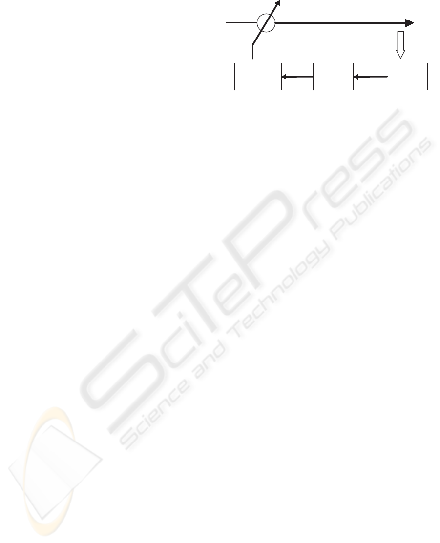
The block diagram of the control system for auto-
matic changing of transformer taps is shown in Figure
1. Each component is modeled as a TDES. Then the
TDES models of the plant components are composed
to form the plant model.
As discussed in Section 2, we first model the
system components by the corresponding ATGs for
Voltage
Sensor
Tap-Changing
Motor
Supervisory
controller
Source
Feeder
Figure 1: Block diagram of control system for automatic
changing of transformer taps.
their untimed behavior. For adding time features we
define the time bounds (lower and upper) for the
events of the system. The plant consists of two main
components:
- Voltmeter
The load voltage must be within a dead-band
(V
0
± ID). where V
0
is “set point”,V
l
is “(measured)
Load Voltage”, △V = V
o
−V
l
is “Voltage Deviation”
and ID is “Insensitivity Degree” which is defined
as the maximum admissible variation of the voltage
before originating a command to change the tap.
Voltmeter reports events associated with the load
voltage using these events :
Initialize Voltmeter (ev11 , [0,inf])
Report |△V | > ID and △V > 0 (ev12 , [0,inf])
Report |△V | > ID and △V < 0 (ev14 , [0,inf] )
Report |△V | < ID— i.e. Voltage Recovered (ev16 ,
[0,inf])
Report Voltage exceeds V
max
(ev18 , [0,inf])
- Tap Changer
The transformer tap changer controls the transformer
ratio “manually” or “automatically” in order to keep
the power supply voltage practically constant, inde-
pendently of the load. If the tap increase (decrease)
is successful, the system returns to a state and waits
for another command. If the tap increase (decrease)
operation fails, the controller changes to the Manual
mode, and waits for another command.
It is assumed here that the tap-changer has 5 steps.
Events associated with the Tap Changer are:
Tap up command (ev31 [5, inf] ),
Tap up successful (ev30 [0, inf] ),
Tap up failed (ev32 [0, inf]),
Tap down command with 5s delay (ev33 [5, inf]),
Tap down command without delay (ev35 [0, inf]),
Tap down successful (ev34 [0, inf]),
Tap down failed (ev36 [0, inf]).
The ATGs for the voltmeter and tap changer are
shown in Figure 2. In order to find the whole sys-
tem’s model, we first find the composition (analogous
to synchronous product in untimed DES) of the ATGs
TIMED DISCRETE-EVENT SYSTEM SUPERVISORY CONTROL FOR UNDER-LOAD TAP-CHANGING
TRANSFORMERS
87
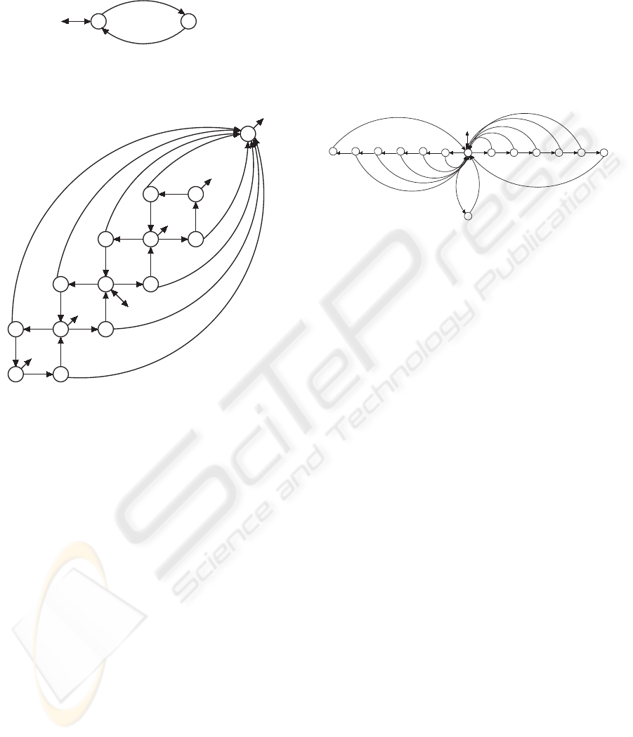
of the system, then find the TTG of the plant by con-
verting the ATG to TTG.
31
31
31
31
30
30
30
30
33,35
33,35
33,35
33,35
34
34
34
34
36
36
36
36
32
32
32
32
11
12,14,16,18
(a)
(b)
Figure 2: ATGs for (a) Voltmeter (b) Tap Changer.
3.3 TDES representation of Control
Specifications
There are two modes of operation: “Automatic” and
“Manual”.
1) Automatic Mode
The tap-changer works in Automatic mode according
to the following logic (control specifications):
a. If the voltage deviation |△V | > ID and △V is
Negative (ev14) then the timer will start and when it
times out i.e. the time delay in occurrence of ev31
elapses then a “tap increase ” event (ev31) will occur
and the timer will reset.
b. If the voltage deviation |△V | > ID and △V is
Positive (ev12) then the timer will start and when it
times out then a “tap decrease ” (ev33) will occur and
the timer will reset.
c. If the voltage returns to the dead-band (ev16), be-
cause of smooth system dynamics or a tap change or
some other system events, then no tap change will oc-
cur.
d. If the voltage exceeds the value set for ”Quick
Lowering” (ev18), then the lowering tap command
without delay (ev35) happens instantaneously.
Figure 3 shows the TDES model of the control
specification in the Automatic mode. It actually im-
plements all the above logic in a single TDES. We
should mention that because in these specifications
we need the events tap up/down command ( 31,33,35)
to preempt tick in some states of the specification
TDES, we should define these events as “forcible”
events. (Section 2 )
31,
16
tt t
33,
16
t
tttt t
16 16 16 16
16
14
12
3518
16
t
1616
16
16
Figure 3: TTG of the control specifications in Automatic
Mode.
2) Auto/Manual Mode
In this mode of operation, we need a model for the
operator action to switch the modes and to override in
abnormal situations. Events 41 and 43 are defined for
operator actions:
Enter “Automatic” Mode (ev41, [0,inf]),
Enter “Manual” Mode (ev43, [0,inf])
The operator can force the system from Automatic to
Manual mode at any time (ev43). System switches
to Manual mode from Automatic mode by a “Man-
ual” command from operator (ev43), or an abnormal
situation such as, failed tap up/tap down. In manual
mode the system is waiting for “Tap-up”, “Tap-down”
or “Automatic” commands. On returning to Auto-
matic mode the controller is reinitialized at state 0 of
the Automatic specification (Fig. 3). A specification
for the Auto/Manual mode (SPEC2) can be achieved
by inserting suitable transitions after the occurrence
of ev31 and ev33 and also by adding a new state as
the “Manual-operation” state. The “Manual” com-
mand (ev43) takes the system from any state (*) to
the Manual-operation state. Then ev41 takes this state
back to the initial state. Fig. 4 shows the TDES model
(TTG) for the control specification in Auto/Manual
mode.
4 IMPLEMENTATION STUDY
The plant and the specification TDES models are im-
plemented in the TTCT software. The supervisory
controller has been designed for the Automatic and
Auto/Manual modes of operation separately.
A. Automatic Mode
The supervisor and the control data for the ULTC in
ICINCO 2006 - SIGNAL PROCESSING, SYSTEMS MODELING AND CONTROL
88

tt t t
tttt t
16 16 16
16
16
14 12
35
18
16
t
1616
16
16
1616
34
36
31
32
30
36
34
33
41
*
43
Figure 4: TTG of the control specifications in Auto/Manual
Mode. The transition 43 from * represent similar transitions
from all states to the “manual operation” state.
the Automatic mode are calculated using TTCT.
SUPER1 = Supcon(PLANT1,SPEC1) (199,301)
MINSUPER1 = Minstate(SUPER1) (52,79)
So we have found a supervisory controller for the
Automatic mode of operation with 52 states and 79
transitions.
B. Auto/Manual Mode
The operator override is incorporated in the model
by the control specification shown in Figure 4. Using
this specification and the new plant model which
is composed by the “Operator” ATG (which has
one state and two transitions i.e. 41 and 43 ), the
supervisory control is synthesized:
SUPER2 = Supcon(PLANT2,SPEC2) (233,547)
MINSUPER2 = Minstate(SUPER2) (56,130)
PMINSUP = Project(MINSUPER2, ‘tick’) (26,53)
As can be seen, the supervisor state-transition size is
(56,130) after applying the “Minstate” operation. By
projecting out tick from the supervisor we can dis-
play its transition structure as the timed activity transi-
tion graph (TATG)(Wonham, 2005). While the TATG
suppresses tick, it does incorporate the constraints on
ordering of activities induced by time bounds. The
TATG of the supervisor for Auto/Manual mode is
shown in Figure 5.
5 CONCLUSION
Synthesis of timed discrete-event based supervisory
control for a tap-changing transformer was discussed
in this work. The tap-changer components and its
logical and temporal behavior have been modeled as
TDES. Controllability of the specification is evalu-
ated and supervisory controllers have been designed
for two different modes of operation using the TTCT
software. It is guaranteed by the synthesis procedure
that the designed supervisors are optimal and non-
blocking. The state size of the supervisory controller
has been reduced for easier implementation. The fol-
lowing topics can be considered for future research
work:
- Implementation of the synthesized supervisory con-
troller on programmable logic controllers (PLC).
- Construction of a hierarchical framework for the
supervisory control problem in a micro-grid electrical
power system containing a tap-changer transformer
and other discrete and continuous elements.
REFERENCES
Afzalian, A. and Wonham, W. M. (2006). Discrete-event
system supervisory controller design for an electrical
power transmission network. In 14th Iranian Confer-
ence on Electrical Engineering (ICEE’06), Tehran.
Brandin, B. and Wonham, W. M. (1994). Supervisory con-
trol of timed discrete event systems. IEEE Transac-
tions on Automatic Control, 39(2):329–342.
GE (2005). Consumer Industrial, DTR - Digital
Tap Changer Controller Instruction Manual GEK-
106305A. p. 7-12.
Hiskens, I. A. and Sokolowski, P. J. (2001). System-
atic modeling and symbolically assisted simulation of
power systems. IEEE Transactions on Power Systems,
16(2): p. 229-234.
Kundur, P. (1994). Power System Stability and Control.
McGraw-Hill.
Lin, S.-Y., Ho, Y.-C., and Lin, C. I.-H. (2004). An ordinal
optimization theory-based algorithm for solving the
optimal power flow problem with discrete control vari-
ables. IEEE Transactions on Power Systems, 19(1): p.
276-286.
Ohtsuki, H., Yokoyama, A., and Sekine, Y. (1991). Reverse
action of on-load tap changer in association with volt-
age collapse. IEEE Transactions on Power Systems,
6(1): p. 300-306.
Ostroff, J. S. (1990). Deciding properties of timed transi-
tion models. IEEE Transactions on Parallel and Dis-
tributed Systems, 1(2):170–183.
Otomega, B., Sermanson, V., and Cutsem, T. V. (2003).
Reverse-logic control of load tap changers in emer-
gency voltage conditions. in Proceedings of Power
Tech Conference, Bologna.
Prosser, J. (1995). Supervisory control of electric power
transmission networks. IEEE Transactions on Power
Systems, 10(2): p. 1104-1110.
Ramadge, P. J. and Wonham, W. M. (1987). Supervisory
control of a class of discrete event processes. SIAM J.
Contr. Optim., 25(1):206–230.
Wonham, W. M. (2005). Supervisory Control of Discrete-
Event Systems. Department of Electrical and Com-
puter Engineering, University of Toronto, available at
http://www.control.utoronto.ca/DES.
TIMED DISCRETE-EVENT SYSTEM SUPERVISORY CONTROL FOR UNDER-LOAD TAP-CHANGING
TRANSFORMERS
89
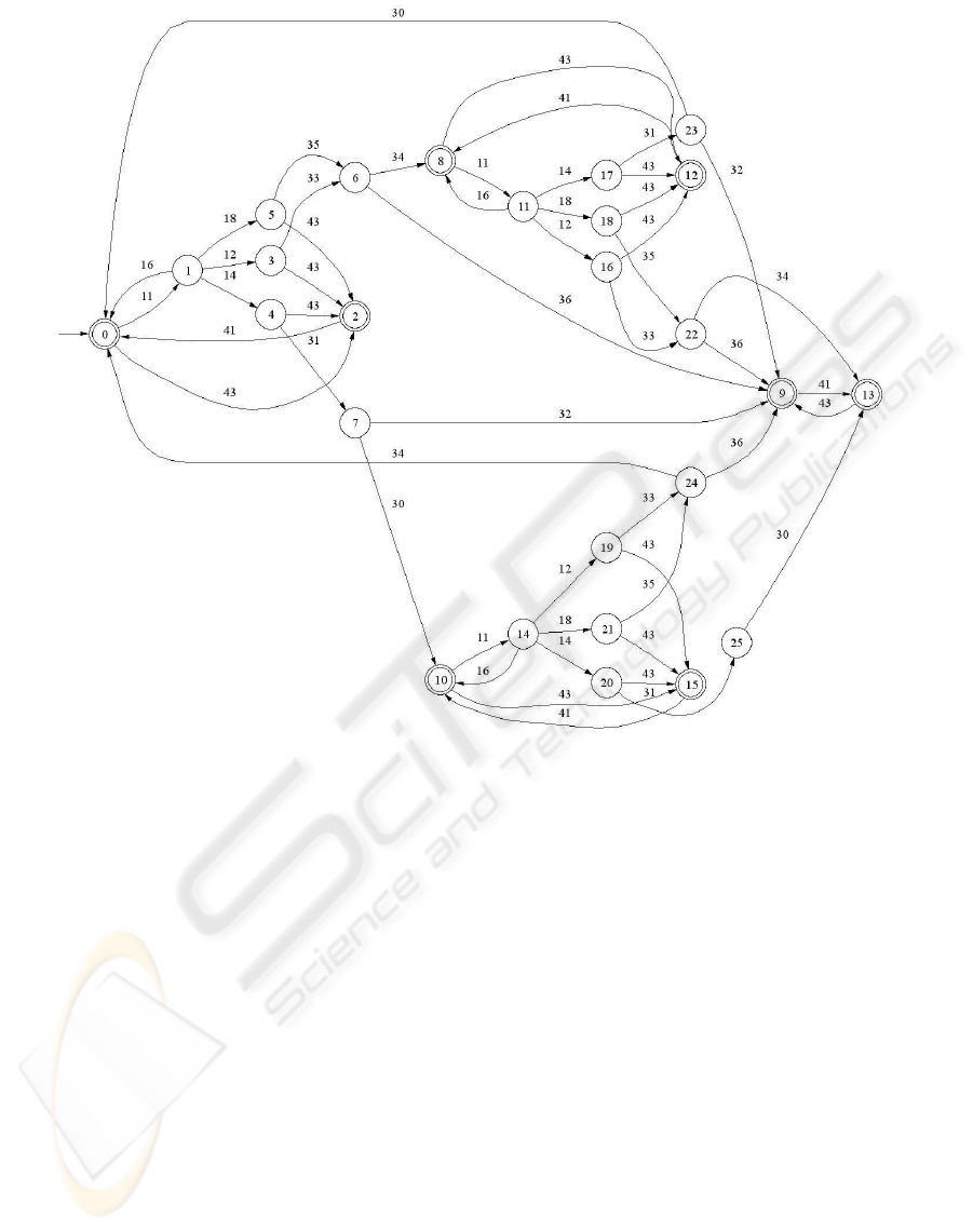
Figure 5: TATG of the supervisory controller for Auto/Manual mode of operation.
ICINCO 2006 - SIGNAL PROCESSING, SYSTEMS MODELING AND CONTROL
90
