
A NEW SENSORIAL AND DRIVING LOCOMOTION
INTERFACE FOR VIRTUAL REALITY
Yves Dupuis, Jean-Luc Impagliazzo, Cédric Anthierens, Dominique Millet
LISMMA (EA 2336) – LIISIM group SUPMECA TOULON
Maison des Technologies, Place Georges Pompidou, F83000 Toulon France
Keywords: Generic interface, Human Gait, Mechatronics, Movement Perception, Virtual Reality.
Abstract: This paper deals with the design of a 1D sensorial and driving locomotion interface for Virtual Reality
applications able to simulate natural walking-in-place. The aim is to provide an unlimited roaming in a
virtual world while physically walking in a constrained area. Most of existing locomotion interfaces do not
allow to walk naturally in terms of steps length and frequency. Furthermore, we define the term “natural
walking” in two complementary ways. The first one is devoted to biomechanical features of human walking,
ie the position, speed and acceleration of human body parts. The second one is related to self-movement
perception, namely the integration of multi-sensorial information such as kinaesthetic, visual and vestibular
information. So, we designed our mechatronical interface using biomechanical and sensorial data of human
walking. The interface is equipped with sensors in order to measure floor reaction forces onto the pedals and
a video tracking device to measure the current positions of user’s feet. Since the program has been written in
C++ language, it is easy to create new automata to control the interface for other applications such as
running. Finally, the implementation of the interface with the virtual environment is described.
1 INTRODUCTION
Virtual Reality can be defined with three main
features : immersion, interactivity and real time.
Immersion gives the feeling to be in the three
dimensional virtual space and interactivity gives the
possibility to interact with the virtual environment.
Moreover, any virtual environment change resulting
from user action is perceived by himself in real time.
In this paper, we introduce a new walking-in-place
interface for Virtual Reality which enhances
immersion and interactivity with the virtual
environment.
Many walking-in-place systems have been
designed since the soaring of Virtual Reality. They
can be divided into three main parts according to
their mechanical structure : pedalling devices
(Distler et al., 1996), 1D treadmill or 2D treadmill
(Noma et al., 1998) (Iwata, 1999) and programmable
foot platforms (Iwata, 2005). All these interfaces are
essentially driving locomotion interfaces : they just
ensure the user to walk on the spot without giving
him a specific sensorial feedback related to
locomotion. In addition to that, kinematics and
dynamics of movements allowed are too limited and
prevent the user from walking naturally.
Our contribution presented in the paper is the
design of a locomotion interface which simulates
natural walking in one direction while globally
keeping the user at the same place. Contrary to
interfaces introduced before, our interface is a
sensorial and driving locomotion interface. That is to
say, we give the user a sensorial feedback he would
have with the similar gait on a real floor. Moreover,
our interface offers kinematics and dynamics of
walking at least equal to those measured during
walking on a floor. Consequently, locomotion on the
interface is closed to natural one and provides
unlimited roaming in the virtual world while being
confined to a limited space in the real world. All
these features contributes to give the user a more
realistic immersion and interaction with the virtual
environment.
The first part of this paper is devoted to the
mechatronics description of the locomotion
interface. Then, we depict the generic feature of
interface control and also how we manage to keep
the user at the same place. The last part centres
around the integration of the locomotion interface
with the virtual environment.
255
Dupuis Y., Impagliazzo J., Anthierens C. and Millet D. (2006).
A NEW SENSORIAL AND DRIVING LOCOMOTION INTERFACE FOR VIRTUAL REALITY.
In Proceedings of the Third International Conference on Informatics in Control, Automation and Robotics, pages 255-260
DOI: 10.5220/0001212302550260
Copyright
c
SciTePress
2 INTERFACE MECHATRONICS
DESCRIPTION
2.1 Mechanical Structure
Our purpose is to design a locomotion interface
which enables the user to walk naturally in one
direction while his position is maintained. Moreover,
each foot has to be controlled independently at any
time. To fulfil that constraint, the design of the
interface is based on pedalling devices, where each
pedal has 1 degree of freedom in translation. As
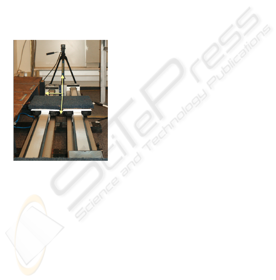
shown in Figure 1, the Cartesian mechanical
structure keeps a privileged direction during
walking.
Figure 1: Locomotion interface structure.
The main advantage of our device is its modular
structure. Indeed, it is easy to upgrade the actuation
mechanism to add new mechanisms for 2D or 3D
locomotion. Currently, our 1D locomotion interface
is composed with two linear independent axles, 2
meters long, each one having one pedal. Each axle is
a belt driven linear transmission which is built on a
compact aluminium beam fitted with V slides. The
drive is provided by a driving belt and pulley to
provide rigidity, speed and accuracy. Each axle is
fitted with a geared brushless motor in order to fulfil
the kinematics and dynamics requirements of
walking.
2.2 Motor Sizing and Controlling
To evaluate precisely motor velocity, acceleration
and torque needed, we have first to describe the
global functioning of our interface. Human gait
cycle is composed of two phases: the swing phase
and the stance phase. During the swing phase, the
user is let a free motion while the pedal is tracking
his foot. Then, the user is pulled back during the
stance phase in order to be kept in place.
Proprioception is the sense of the position of parts
of the body, relative to other neighbouring parts of
the body. In order to design our interface, we have to
take the major features related to proprioception into
consideration. This kind of study points out
proprioceptive specifications for design. Namely, it
seems necessary to ensure a minimum linear pedal
speed and acceleration in order to have kinematics
and dynamics features of walking close to natural
one.
During the swing phase, pedal velocity and
acceleration must be close or even equal to foot ones
during natural walking. In sagittal plane, foot speed
has a parabolic shape and can be up to 4.5 m/s,
whereas the acceleration can be up to 28 m/s². But it
is important to underline the fact that while one foot
is in swing phase, the other one is pulled back. So, in
a global referential the maximum pedal speed during
swing phase is approximately half the value quoted
before. The most restrictive phase for motor sizing is
the stance phase. Indeed, the pedal has to enforce a
trajectory of pulling back while the user applies
forces onto the pedal. This trajectory is computed
thanks to biomechanical (Faure et al., 1997) and
movement perception features in order to give the
user a sensorial feedback close to natural one.
Concerning motors control, we chose brushless
motors which provide very high accelerations. Each
motor is connected to a gear whose ratio is 5.
Transformation from rotation to linear movement is
provided by a driving belt and pulley whose radius is
such that linear speed can be up to 3.2 m/s. Our
application requires to enforce position, speed or
torque trajectories depending on the current phase of
walking and the strategy of pulling back we use. To
avoid switching between position, speed or torque
mode control, the brushless motors are controlled in
torque mode. Since the servo control adjusts itself in
torque mode, we need to identify the transfer
function between motor torque and pedal linear
speed to set correctly our control law. The transfer
function has been identified as a second order one.
The identification of mechanical parameters such as
static friction force, adherence force, viscous friction
and time constant has been performed. To control
the pedals in position mode, we designed a
numerical PID control law. To make the system
more stable and have the desired time response
characteristics, we placed the closed-loop poles to
the desired locations.
X
Y
Z
ICINCO 2006 - ROBOTICS AND AUTOMATION
256
2.3 Instrumentation
The interface is also equipped with tactile sensors in
order to detect the contact between the feet and the
pedals. Each pedal has a sagittal force measurement
sensor which consists of a top plate connected to a
base plate separated by a force S-shaped sensor and
three rails so that all sagittal loads applied to the top
plate go through this sensing element. In the future
the interface will be equipped with two 6 degrees of
freedom sensors in order to compute the centre of
pressure during stance phases. Sensor data are used
during stance phases to compute the pedal trajectory
which goal is to pull back the user while giving him
specific kinaesthetic and/or vestibular sensorial
feedback.
A specific tracking device using a single video
camera has been designed to track user’s feet during
swing phases. Our algorithm is based on an
approach allowing to track 2D patterns in image
sequences (Jurie et al., 2000). We use a CCD camera
which resolution is 384 x 288 pixels and two
patterns placed on user’s shins.
During image sequences, the principle is to
measure the difference between two reference
patterns and the current patterns which are different
because of patterns movements. Sampling are made
into elliptic image areas because it is a geometric
shape invariant to planar distortions. Each ellipse
have five geometric parameters (equation 1) which
are :
cc1 2
E = (X , Y , R , R , θ)
eq.1
ΔE is the difference between the real and
predicted ellipse parameters. Let
ref
I be the
reference shape vector composed of pattern’s pixels
sampled into the ellipse and
C
I the current shape
vector. The correction between two images is given
by equation 2:
t
ref c
ΔE = A.(I - I ) = A.ΔI
eq.2
The algorithm uses the difference between
reference and current pattern to compute the
appropriate sampling ellipse deformations to fit
current pattern to reference pattern. For both
ellipses, these corrections are computed thanks to
two interaction matrix (A) estimated during a
learning phase. At the beginning of this phase,
ellipses are manually placed on the two patterns to
track. Then, the ellipses are distorted by randomly
changing their five parameters. For each distortion,
the variations of the two ellipses parameters vectors
(ΔE) and the variations of sampled patterns (ΔI) are
stored. Basics geometric relationships are used to
compute the global patterns positions X,Y,Z and θ
(ZY planar rotation). In this method, the rotation
around lateral axis does not affect the computation
of global patterns positions. Nevertheless, rotation
around vertical axis cannot be measured with one
single camera and greatly affects the computation of
patterns positions. We made the hypothesis that
rotation around vertical axis is negligible during
walk.
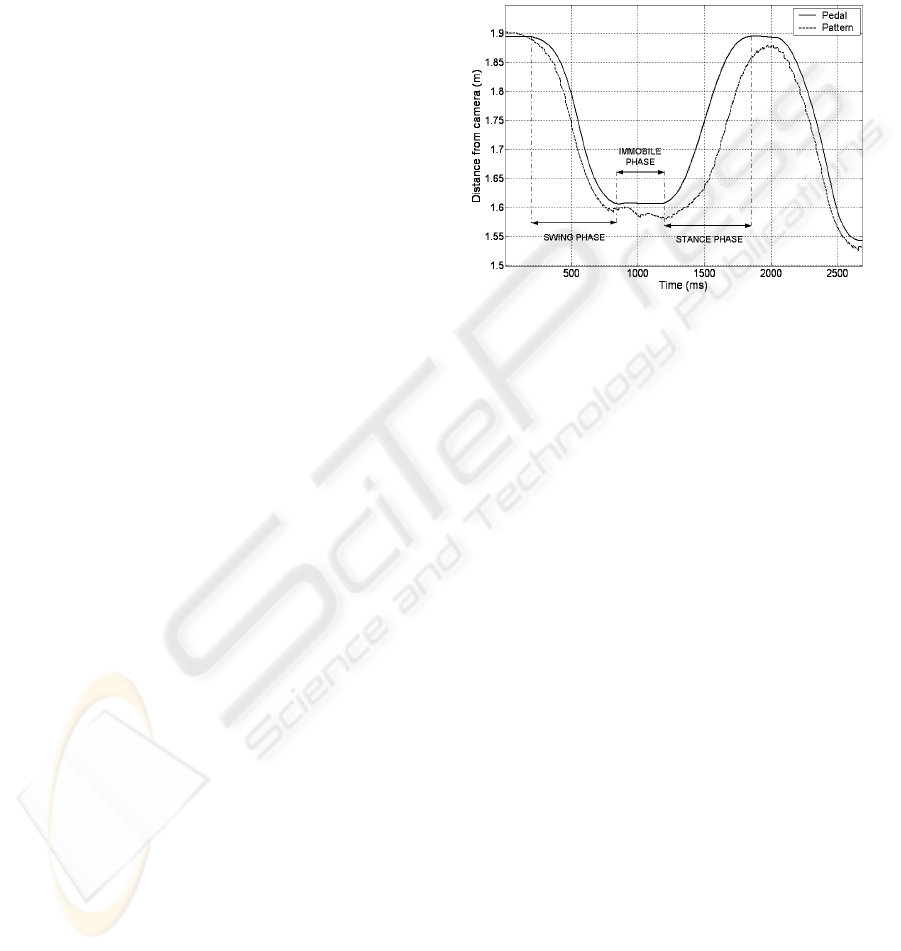
Figure 2: Comparison between sagittal trajectories of left
pattern and left pedal during the locomotion.
Figure 2 shows our tracking algorithm is
efficient for our application because the pedals are
always under user’s feet at the end of the swing
phases even if there is a slight delay of the pedals at
the beginning of each swing phase. During the
double support phase (called immobile phase), the
pedal enforces a constant position whereas the
pattern placed on user’s shin goes naturally ahead.
That is the reason why we notice in Figure 2 a
decrease of pattern sagittal translation during this
phase. During the stance phase, there is a gap
between pedal and pattern positions because the user
is pulled back and consequently the foot rotates
around Y axis. But this drawback is not harmful in
our application because it only occurs during stance
phases when the pedal are not driven with tracking
data.
Finally, tracking data are disrupted because of
camera resolution and local lightening variations. To
minimise that unwanted noise, images are
normalised and weighted least square method is used
to smooth and predict tracking data. During swing
phases, it is necessary to have a smooth trajectory of
tracking data in order to avoid abnormal pedal
variations in translation. Moreover, the prediction is
a good way to make up for the initial pedal delay at
the beginning of each swing phase.
A NEW SENSORIAL AND DRIVING LOCOMOTION INTERFACE FOR VIRTUAL REALITY
257
3 INTERFACE CONTROL
In this part, we underline the generic feature of our
locomotion interface. Indeed, everyone has a
singular way of walk : short or long steps, low or
high frequency steps. These walk parameters are
notably due to our height, weight and others
anthropomorphic features. The problem is how
could we manage all these different people to walk
on our interface as if they were on a real floor
without perturbing them.
3.1 Control Strategy
Despite his variety, human walk can always be
described by a sequence of precise states : swing
phase, single and double support phases. Double
support phase remains an important state which
differentiates walk from running. In our case, the
transitions between these states are performed
according to sensors data which give us the
information of contact between the foot and the
pedal.
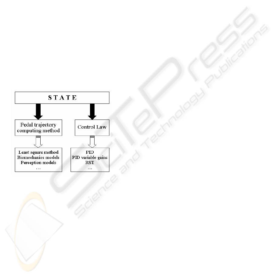
Figure 3: Generic state description.
Each automaton state is defined with a particular
pedal trajectory computation method and a particular
control law. Indeed, depending on the state, it can be
useful to use different control laws. For instance,
during swing phase, we prefer using a control law
with a time response as low as possible. Moreover,
in that state, the trajectory of the pedal is computed
from video camera data whose frequency is different
from time step servo-control. As said before, these
data are smoothed and extrapolated with the
weighted least square method. During the stance
phase, the trajectory of pulling back is computed
with other data (biomechanical and/or sensing ones).
In addition to this, the control law used in this phase
is different than one used during swing phase
because we prefer here to ensure a smooth and
precise trajectory of the pedal. All these remarks
lead us to create a generic state for interface control
such as described in Figure 3.
3.2 Automaton Implementation
Obviously, it is possible to define several automata
to pilot the locomotion interface. Here, we introduce
the implementation of the simplest automaton which
enables the user to walk forward and backward.
Before running any automaton, the user is standing
up and a short initial phase is performed in order to
identify several parameters such as the pattern’s
height and the initial patterns positions comparated
to the pedals. We remind that we track user’s shins
thanks to patterns and these initial parameters are
used to evaluate the feet positions during the swing
phases. Moreover, the use of sensors to measure
vertical forces is very useful because it is a
parameter which combination with user’s height
gives information about step lengths and walk
frequency.
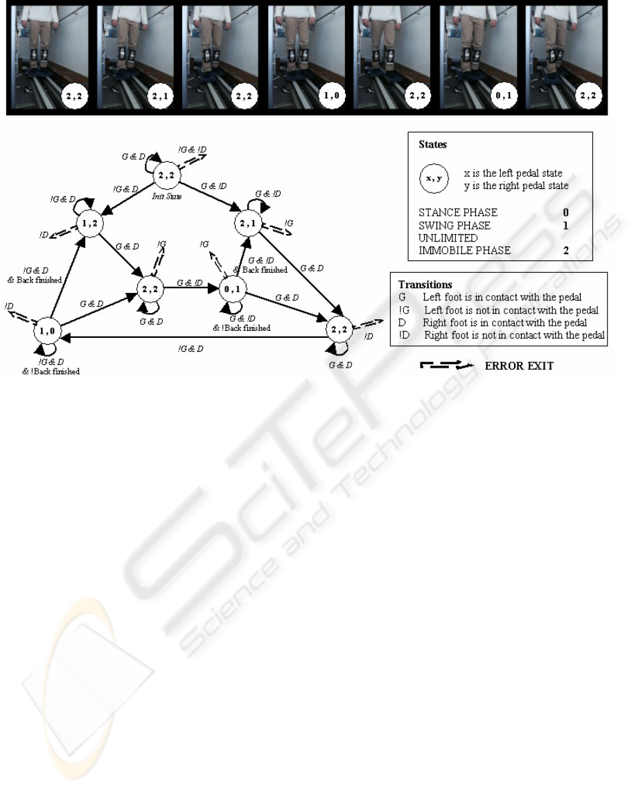
After this initial phase, the automaton pilots the
locomotion interface. The automaton presented in
Figure 4 is composed of seven states, each one
describing the current state of left and right pedals :
stance phase, swing phase or double support phase.
During a stance phase, the pedal enforces a
trajectory computed from biomechanical and/or
perception models so as to keep the user in place.
Currently, we use the duration and the travel
distance of the last swing phase to compute this
trajectory. The aim is to keep globally the centre of
mass of the user at the same place while pulling him
back. To do so, we identified the sagittal trajectory
of centre of mass during the walk on a floor surface
and we apply to the pedal the appropriate trajectory
to cancel the movement of user’s centre of mass.
During the swing phase the pedal follows user’s foot
thanks to tracking data such as described previously.
At last, during a double support phase, the system
maintains the current pedal position even if the user
acts on the pedal. Pictures in Figure 4 show a state
sequence corresponding to a walk cycle with an
initial swing right phase.
This software has been written in C++ language
and designed in such a way that it is easy to replace
an automaton by an other one, just as easily a state
by an other one and even a control law by an other
one. In the example introduced in Figure 4, the
pedals are maintained immobile during the double
support phase. For instance, it would be nothing to
set new pedals trajectories to cancel the forward or
backward drift which may appears after a long time
walk.
Regarding the high dynamic actuators used,
safety aspect is a very critical point. The interface is
ICINCO 2006 - ROBOTICS AND AUTOMATION
258
equipped with software and hardware stops. The
video tracking task is also secured : any tracking
algorithm failure, any discording data or any data
transfer failure cause the emergency stop of the
interface. At last, the automaton manages illegal
transitions between states and suspicious walk
phases such as very short swing phases.
4 INTEGRATION IN THE
VIRTUAL ENVIRONMENT
During the locomotion, self-movement perception is
given by the combination of kinaesthetic, visual and
vestibular information (Berthoz, 1997). It clearly
seems necessary that sensorial and motivity
validation of our interface need to visually immerse
the walker. As shown in Figure 5, this visual
rendering has been performed thanks to the
FLATLAND simulator developed in our laboratory.
This one can deal with pure simulation of complex
physical systems and can also be used as an
interactive multi-sensorial platform for Virtual
Reality thanks to its generic input/output data
interfaces. Of course, FLATLAND’s kernel ensures
the real time synchronisation of all interfaces with
their respective frequency.
In our case, we just had to use the specific PVM
(Parallel Virtual Machine) visual module interface
of FLATLAND which generates video frames for
fixed screen projection. This module only needs the
screen dimensions, the current virtual eye position
and real eye position from the screen. The current
real eye position is computed into the interface
automaton thanks to a biomechanical model giving
the head position from feet ones. The virtual eye
position is computed from the real eye position by
cumulating the feet’s displacements as if the user
was walking on a fixed ground surface. Depending
on the application, a distance scale factor between
real and virtual world can be applied.
Since it is also possible to give to FLATLAND
the user head angular positions, it will be interesting
to use some header tracking device to verify if we
can have the feeling of walking on a plane surface
while physically walking in a straight direction.
In order to improve the immersion feeling, 3D
spatial sound rendering can be added to the virtual
scene. This additional feature is useful to cover
interference noises coming from actuators, sliding
and other background noises, even if the major
source of noise remains the video projector.
Figure 4: Example of an hybrid automaton used to pilot the locomotion interface.
A NEW SENSORIAL AND DRIVING LOCOMOTION INTERFACE FOR VIRTUAL REALITY
259
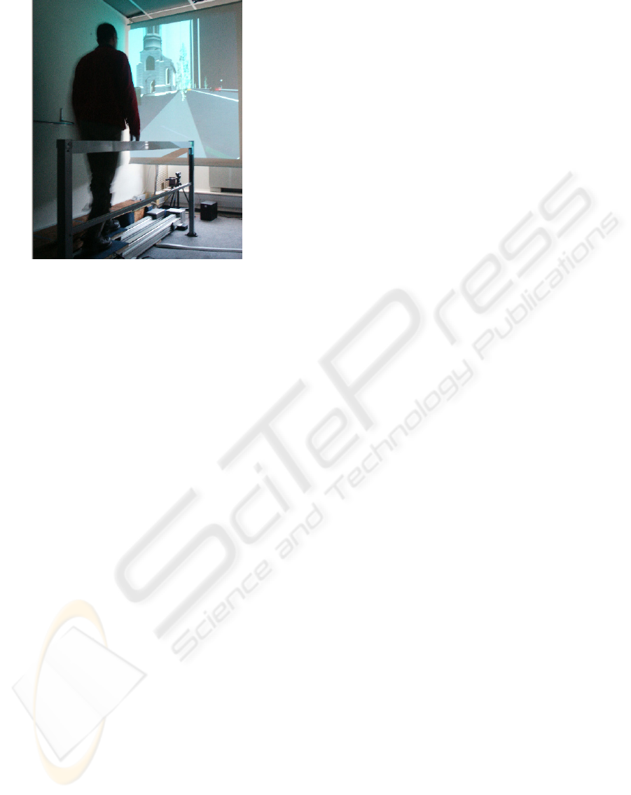
Figure 5: An example of virtual scene.
Finally, the interface functioning needs the
execution of three tasks, each one running on a
dedicated PC : (1) the tracking task sends position
data to the automaton task (2) via a serial port
communication, which one pilots the interface and
provides via PVM bus the virtual and real eye
position and orientation (3) to FLATLAND
simulator every visual step time.
5 CONCLUSION AND
PERSPECTIVES
We have introduced a new sensorial and driving
locomotion interface for Virtual Reality
applications. The interface is composed with two
independent pedals controlled with brushless
motors. The design has been performed by taking
into account biomechanical and movement
perception features. Thanks to a generic
programmation, it is easy to implement new control
automata to pilot the interface with other strategy of
walk. For instance, it would be interesting to
implement an automaton for running or cross-
country skiing applications.
Currently, the interface allows the user to walk
forward or backward, slowly or rapidly, with short
or long steps. Moreover, it is possible to stop
walking at any time without being disturbed. In
other words, the kinematics and dynamics of walk
are equal to natural ones.
The experiments have been performed without
harness in order to let the user a free way of walk.
Users do not feel any imbalance due to locomotion
interface. This feature is in favour of a good self-
movement perception. To evaluate self movement
perception, we have to take into account the visual
and vestibular interactions. Indeed, user’s vestibular
system is stimulated while he is kept in place
because of head linear accelerations. So, any
discordance between visual and vestibular
information would be detected and cannot but entail
the user to feel sick.
Future works will be to develop the sensorial
feature of our locomotion interface. The main
problem will be to avoid any discordance between
visual and vestibular systems while walking on our
interface and being visually immerged in the virtual
scene. Finally, the modular design of the interface
give us the possibility to improve the mechanical
structure for 2D or 3D locomotion.
ACKNOWLEDGEMENTS
The authors would like to express their gratitude to
CETIM for its industrial support.
REFERENCES
Berthoz A., 1997. “Le sens du mouvement”, Ed. Odile
Jacob, collection sciences.
Distler H.,Bulthoff. H.H., « Psychophysical experiments
in virtual environments », Virtual Reality World’96.
1996, Stuttgart, Germany.
Faure F., Debunnes G., Cani-Gascuel M.P., Multon F.,
1997. « Dynamic analysis of human walking »,
Eurographics Workshop on Computer Animation and
Simulation, p. 95-107.
Iwata H., 1999. Walking about virtual environments on an
infinite floor. IEEE Virtual Reality’99 Conference.
Houston, Texas, USA.
Iwata H., Yano H., Fukushima H. & Noma H., 2005.
CirculaFloor. IEEE Computer Graphics and
Applications. Volume 25, Issue1, p 64-67.
Jurie F., Dhome M., 2000. « Un algorithme efficace de
suivi d’objets dans des séquences d’images »,
Reconnaissance des Formes et Intelligence Artificelle,
Paris, p. 537-546.
Noma H. & Miyasato T., 1998. Design for Locomotion
Interface in a Large Scale Virtual Environment,
ATLAS : ATR Locomotion Interface for Active Self
Motion, ASME-DSC-Vol. 64, p 111-118.
ICINCO 2006 - ROBOTICS AND AUTOMATION
260
