
AUTOMATA BASED MODELLING AND SIMULATION
Application in an Industrial Software Environment
Vasileios Deligiannis
Electrical & Computer Engineering Dept., University of Patras, 26500, Rio-Patras, Greece
Stamatis Manesis
Electrical & Computer Engineering Dept., University of Patras, 26500, Rio-Patras, Greece
Keywords: Automata, Modelling, Simulation, Industrial systems.
Abstract: Contemporary industrial systems are hybrid systems, and hybrid automata and Petri Nets are the most used
approaches to model such systems. Despite academic efforts these two approaches did not meet wide
acceptance when proposed for industrial use, mainly because they are application depended. In this paper, a
recently proposed hyper-class of hybrid automata is presented, which seems to cover this weakness.
Illustrating its use, an application of this new formulation method in an industrial software environment is
given. The given example is taken from a chemical industry and uses PID controllers to control continuous
variables, while the whole project was developed in a SCADA software platform.
1 INTRODUCTION
Most contemporary industrial systems are described
as hybrid systems, since they are governed by
discrete state controllers, whose internal state
transitions are triggered by the value of some
measured continuous physical quantity (temperature,
flow rate, time, etc.). The importance of modelling
and simulation of industrial production systems is
generally acknowledged and hybrid automata
(Antsaklis, 2000) and Petri nets (Peterson, 1981) are
the most used approaches for modelling hybrid
systems. But these methods did not meet wide
acceptance when proposed for industrial use,
primarily because they are application depended, or
more accurate domain depended. A new automata-
type method (Deligiannis, 2005) seems to avoid this
dependence, offering the convenience of modelling
various types of industrial systems without any
restrictions on system’s properties. It borrows some
characteristics from several types of automata
(Khoussainov, 2001), such as the control graph with
a finite set of states and transitions between those
states. It models hybrid systems handling both
discrete and real valued variables combining flow,
invariant and guard conditions from hybrid
automata, with clock constraints and delayed inputs
from timed (Allur, 1994) and PLC automata (Dierks,
1997). In addition, introduces new modelling
parameters as reset table at each transition and
hierarchical classification of executable events at
each state. Application independence derives from
the fact that new method is a hyper-set of every
other type of automata and hence is less application
depended compared to any of them.
Apart from the used modelling method and despite
huge advances in the field of control systems
engineering, PID still remains the most common
control algorithm in industrial use today. It is widely
used because of its versatility, high reliability and
ease of operation (Astron, 1995). PID systems’ main
advantage on applying control is that there is no
need to obtain a dynamic model.
In this paper an example of industrial relevance
is presented. A three tank system is modelled, using
the new automata-type model, and implemented for
simulation and verification in an industrial software
environment. A PID controller was developed to
control system’s continuous dynamics.
Implementation took place in CX – Supervisor, a
Supervisory Control And Data Acquisition
(SCADA) software by OMRON. Taking advantage
of software’s animation capabilities, screens
193
Deligiannis V. and Manesis S. (2006).
AUTOMATA BASED MODELLING AND SIMULATION - Application in an Industrial Software Environment.
In Proceedings of the Third International Conference on Informatics in Control, Automation and Robotics, pages 193-196
DOI: 10.5220/0001211401930196
Copyright
c
SciTePress
resembling real system were constructed in order to
visualize system’s operation.
2 THE HYPER – CLASS OF
HYBRID AUTOMATA
This new hyper-class of hybrid automata was firstly
introduced in (Deligiannis, 2005). Method’s main
aim is to bridge the gap between academic methods
and real industrial applications, being suitable for
modelling a large variety of industrial systems. It
introduces new formulation parameters in addition
with some of the conventional methods, and
especially from the several types of automata.
Definition 1. We define an automaton by the 12-
tuple:
,,,, , ,,, ,, ,
X
Z
A
X Z Q Init Flow L S W E R R=Σ
.
Its structure is composed by the following sets:
• System’s variables:
o Real-valued variables:
{
}
123
, , ,...,
m
X
xx x x=
o Discrete variables:
{
}
123
, , ,...,
k
Z
zzz z=
• Set of states:
{
}
123
, , ,...,
n
Qqqq q=
• Alphabet or set of events:
{
}
123
, , ,...,
λ
σ
σσ σ
Σ=
, which can be:
o Discrete variables.
o Conditions over the real-valued variables.
o Any combination of them.
• Initial conditions: Init
o
0
XX=
,
0
Z
Z=
and
0
q
• Flow conditions:
o
()
,0FXX=
o
()
1ii
Z
GZ
+
=
• Invariant conditions:
{}
123
, , ,...,
n
L = AA A A
• Restrictions or safe values:
{
}
123
,,,...,
n
Ssss s=
• The set of events to be ignored until the
satisfaction of restrictions:
{
}
123
, , ,...,
n
Wwww w=
with
i
w ⊆Σ
.
• Set of transitions:
XZ
E
QQ R R⊆××Σ× ×
• Reset table for each transition:
o
X
X
R= ,
Z
Z
R=
Each set
(
)
,',, ,
X
Z
qq r r
σ
represents a transition
from state
q
to state
'q
, which is caused by the
event
σ
∈
Σ
. Set
X
X
rR⊆
gives the real-valued
variables to be resettled during this transition, while
set
Z
Z
rR⊆
gives the discrete variables.
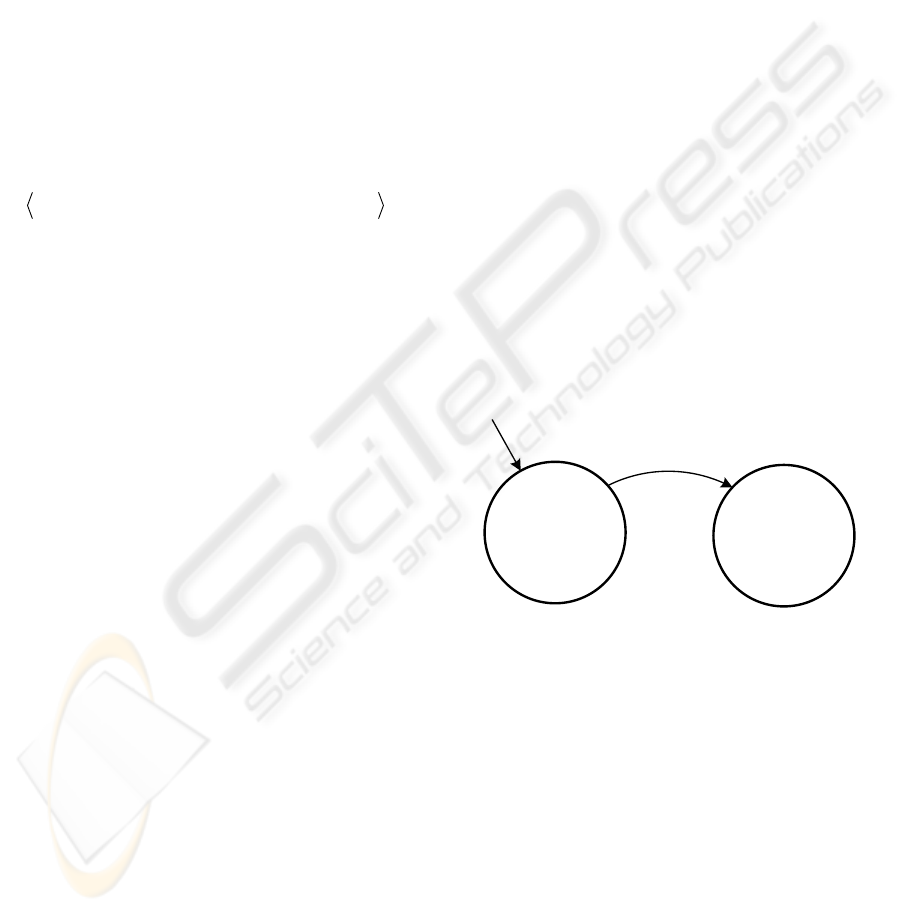
As shown in figure 1, each state
i
q
has a
corresponding set of parameters, which are:
• Flow conditions:
o
(
)
,0
i
FXX
=
o
(
)
1
j
ij
Z
GZ
+
=
• Active events at present state:
i
Σ⊆Σ
. Set
i
Σ
has, by definition,
ζ
elements, each one of
which belongs to set
Σ
.
{
}
,ik
ij
σ
Σ=
, where
i
is
the present state,
1, 2,...,k
ζ
=
and
[
]
1,j
λ
∈
.
Index k also denotes transitions priority caused
by different events. If two events occur
simultaneously and cause two different
transitions, transition with the lower index k will
take place.
• Invariant conditions:
i
A
• Restrictions or safe values:
i
s
• Set of events to be ignored until the satisfaction
of restrictions:
i
w
(
)
()
{}
[]
{}
00
00
,0
3
2,0
5
1,0
20
01
0
,
,...,,
0
ws
XorX
ZGZ
XFX
ii
AA
≥≤
=Σ
=
=
+
ζ
σσσ
()
()
{}
[]
{}
11
11
,1
7
2,1
1
1,1
30
11
1
,
,...,,
0
ws
XorX
ZGZ
XFX
ii
AA
≥≤
=Σ
=
=
+
ζ
σσσ
Σ
∈
σ
[
]
ZX
RZRX =
=
,
0
0
ZZ
XX
=
=
0
q
1
q
Figure 1: A simple automaton with two states.
3 A THREE TANK SYSTEM
Let us suppose an example from a chemical
industrial procedure, which consists of three
different tanks, as shown in figure 2. Tanks 1 and 2
contain two different liquid materials and both feed
tank 3 simultaneous. The whole procedure starts
through a start button. When start button is pressed,
valves g and h open and both liquids flow to tank 3.
Simultaneously, the mixing process starts by turning
on the mixer p. There is a specific ratio between
flows from tanks 1 and 2, according to the chemical
procedure. Hence, at least one of the valves has to be
controlled in order to meet procedure’s
ICINCO 2006 - SIGNAL PROCESSING, SYSTEMS MODELING AND CONTROL
194
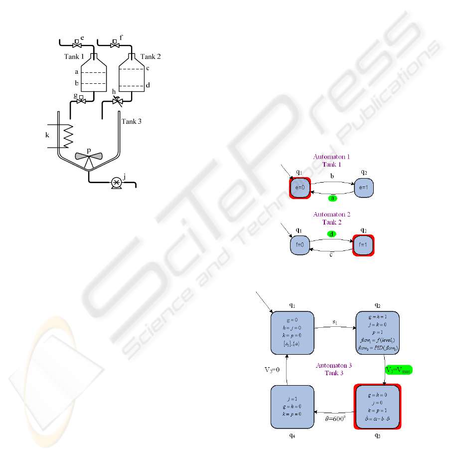
requirements. The controller used is PID, regulating
flow from tank 2 and is described in the next section.
When liquid’s mass in tank 3 is 150 lt. both valves g
and h close and the heating phase starts. Heating
takes place by turning on heater k and stops when
mixture’s temperature arises to 600
o
C. At that time,
mixer and heater turn off and valve j opens until
tank 3 is empty.
Valve e is automatically controlled, so as to keep
level in tank 1 between a and b. When level in tank
1 falls to b, valve e opens until level arises to a.
Equivalently, valve f is controlled to preserve level
in tank 2 between c and d limits.
Figure 2: Example from chemical industry.
4 SUPERVISOR – SCADA
ENVIRONMENT
SCADA is the acronym for Supervisory Control
And Data Acquisition, a computer for gathering and
analyzing real time data. SCADA systems are used
to monitor and control a plant or equipment in
industries. A SCADA system gathers information
from the plant, transfers it back to a central site,
carrying out necessary analysis and control, and
displaying the information in a logical and organized
fashion. SCADA systems were first used in the
1960s and since then, most of industrial engineers
have become familiar with their use. This is the
main reason for choosing CX – Supervisor as the
software platform for illustrating the use of the new
automata-type model, since this new method was
presented with industrial orientation. In addition, CX
– Supervisor comes with a Run-Time environment,
where simulation of a system can take place.
The system, described in the previous paragraph,
can be seen as wholeness, or in a different approach,
as three independent subsystems, each one modelled
with a relative automaton. First two automata are
very simple controlling tanks’ inlet in accordance to
liquids level. Third automaton is slightly more
complex. It has a restriction in state q
1
, where event
s
1
will be delayed until tank 1 is full (a=1). In
addition states q
2
and q
3
have flow conditions
according to which system’s variables change their
value. State q
3
has a flow condition giving
temperature’s rise until the upper limit of 600
o
C,
when the heater is on. State q
2
implements the PID
controller mentioned in the previous section in order
to satisfy process criteria. More analytically, flow
from tank 1 to tank 3 depends on liquid’s level in
tank 1 which fluctuates between a and b. Hence, the
controller used has to adjust valve h so as to keep the
desired rate between the two liquids’ flow.
Based on these automata, a project was built in
CX – Supervisor, a SCADA software environment
by OMRON. A screen resembling automata’s
executions was developed. In this screen active state
in each automaton turns red, while last transition is
denoted with a green sign. Screenshots are depicted
in figures 3 and 4.
Figure 3: Screenshot of automata 1 and 2.
Figure 4: Screenshot of automaton 3.
Here, we have to mention that each state’s
components were reproduced by a script written at
CX – Supervisor’s embedded script editor in
AUTOMATA BASED MODELLING AND SIMULATION - Application in an Industrial Software Environment
195
accordance to the guide described in (Deligiannis,
2006). Due to software limitations and capabilities,
differential equations were transformed to difference
equations (Hamming, 1973). Especially for the
controller, a PID algorithm given by SIEMENS was
used. This algorithm calculates a particular
manipulated variable increment dY
k
at an instant
()
A
Tkt ×=
according to the following formula:
()
[
()
⎥
⎦
⎤
⎟
⎟
⎠
⎞
⎜
⎜
⎝
⎛
+⋅−⋅⋅+
+⋅+⋅−⋅=
−−
−
12
1
2
2
1
kkk
A
V
k
N
A
kkk
dDXWXW
T
T
XW
T
T
RXWXWKdY
At the instant t
k
, manipulated variable Y
k
is
calculated as follows:
∑
=
=
k
m
k
dYY
0
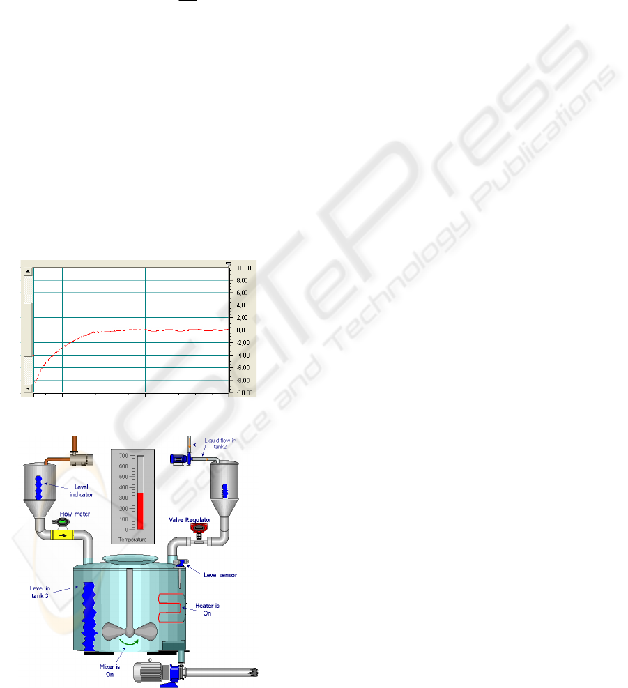
Using the embedded features of our SCADA
software, we have an overall supervision of our
system. Data Log Viewer helps us test PID’s
operation since deviation from set point is measured
and depicted on line. An operation example showing
the percent of set point deviation is depicted in
figure 5.
Figure 5: Percent of set point deviation.
Figure 6: A screenshot from CX – Supervisor.
A SCADA software, just like CX – Supervisor,
gives to the developer the opportunity to create
screens resembling the real system. In figure 6, a
screenshot of the project created, is shown. Each
tank has the relative level indicator showing to the
operator the liquid level inside the tank. The exact
level is displayed in a relative table, where all
system variables are shown. Taking advantages of
software’s animation capabilities, liquid flow is
visualized as also mixer’s movement.
5 CONCLUSIONS
A recently proposed automata-type method for
modelling industrial systems was used in this paper
illustrated through an example from a chemical
industry. The given example was modelled and
simulated in a SCADA software environment with
run-time feature. Regarding future work on this
field, one may have to examine if a model
implemented in a SCADA software can be used not
only for simulation but for control as well. A
supervisor control station connected with a
programmable logic controller would interact with a
plant and control it.
REFERENCES
Alur, R. and Drill, D. L., 1994. A Theory of Timed
Automata. In Theoretical Computer Science, 126:183-
235.
Antsaklis, P. J., 2000. A Brief Introduction to the Theory
and Applications of Hybrid Systems. In Proceedings
of the IEEE Special Issue on Hybrid Systems: Theory
and Applications, Vol. 88, pp. 879-887.
Astron, K. J. and Hagglund, T., 1995. PID controllers:
Theory, design, and tuning, Research Triangle Park,
NC, USA:ISA.
Deligiannis, V. and Manesis, S., 2005. Introducing a new
mathematical abstraction for modelling real time
systems. In 16
th
IFAC World Congress, Prague.
Deligiannis, V. and Manesis, S., 2006. Building
Automata-Type Simulation Models for Undergraduate
Teaching Industrial System Analysis. In ACE 2006,
has been submitted for review.
Dierks, H., 1997. PLC-Automata: A New Class of
Implementable Real-Time Automata. In ARTS’97,
LNCS, Springer Verlag.
Hamming, R. W., 1973. Numerical Methods for Scientists
and Engineers. McGraw-Hill, New York.
Khoussainov, B. and Nerode, A., 2001. Automata theory
and its applications, Birkhauser, Boston.
Peterson, J. L., 1981. Petri Net Theory and the Modelling
of Systems, Prentice-Hall Inc.
ICINCO 2006 - SIGNAL PROCESSING, SYSTEMS MODELING AND CONTROL
196
