
A SPECIFIC LOCOMOTION INTERFACE FOR
VIRTUAL REALITY
Design of a Wheelchair Type Haptic
Cédric Anthierens, Jean-Luc Impagliazzo, Yves Dupuis
LISMMA EA2336, Supmeca Toulon, Maison des Technologies, Place G Pompidou, F83000 Toulon, France.
Eric Richard
ISEN Toulon, Maison des Technologies, Place G Pompidou, F83000 Toulon, France.
Keywords: Virtual environment, disabled persons, multisensorial interfaces.
Abstract: This paper presents a recent advance in Virtual Reality (VR) related to building design or development of
public places. It focuses on the design and implementation of a wheelchair type haptic to simulate ease of
access and displacement of a disabled person in a wheelchair in public places. A VR platform equipped with
this haptic system provides a Virtual Environment (VE) that represents either a street scene or an interior
building scene. This VE is useful for architects who want to efficiently design facilities for disabled access
during the design phase. The first part of this paper deals with the lack of consideration of disabled access in
everyday places and therefore the need to improve facilities, as emphasized by French law. The second part
deals with specifications and expected performances of the VR platform, specifically with regard to the
requirements of the whole Virtual Environment. The third part focuses on the mechatronic design and
explains how each part of the interface works to produce good renderings and a high level of realism with
respect to the main goal defined before. The implementation phase and integration of this specific
behavioural interface into the VR platform is presented in the fourth part. The last part before the conclusion
and perspectives discusses tests and final results obtained from total immersion within two types of
simulated interior environment.
1 INTRODUCTION
For a long time we have observed everyday
difficulties encountered by disabled persons that
could be avoided if the design of private or public
places took their handicap into account. Facilities
satisfying able bodied or disabled persons can
usually be implemented but this solution is not often
chosen. For example, too many public places such as
restaurants, concert halls and trains are not yet
equipped to receive persons who rely on a
wheelchair for their mobility. Accessibility to such
places is therefore reduced or, in some cases, is
impossible.
A recent French law regarding the rights and the
opportunities of disabled persons imposes standards
to improve accessibility for all on both existing and
new buildings. The L.111-7 article of building and
house French code states that public or private
buildings or facilities, whether inside or outside
must be accessible to all and notably to disabled
persons regardless of the type of handicap
considered.
Our study focuses primarily on a physically
disabled wheelchair user. Beyond the simple respect
of the building standards in force, it could be
interesting for architects to estimate the importance
of these standards in use for the end-user. Indeed the
difficulties of moving a wheelchair on a banked
walkway or to cross a small step between two rooms
for example is often not understood or perceived by
designers and therefore they do not change their
design according to these considerations.
This is the reason why we would like to give
architects the possibility to experience a virtual
version of a room or exterior space he/she has
designed in which he/she can move with a
426
Anthierens C., Impagliazzo J., Dupuis Y. and Richard E. (2006).
A SPECIFIC LOCOMOTION INTERFACE FOR VIRTUAL REALITY - Design of a Wheelchair Type Haptic.
In Proceedings of the Third International Conference on Informatics in Control, Automation and Robotics, pages 426-431
DOI: 10.5220/0001210904260431
Copyright
c
SciTePress

wheelchair. This would enable architects and
engineers to better understand the interest to design
differently by taking into account the mobility
difficulties of everybody (Harrison, 2004).
The benefits of this study are numerous because
it can help architects and designers by providing a
virtual validation of their modelling, but it can also
contribute to change standards to be more suitable
for the everyday life of wheelchair users.
These improvements could follow different
criteria according to the end user point of view such
as comfort, security, accessibility. The aim of this is
to provide a VE as a useful tool to help designers
and architects. This is why our VE highlights the
main nuisances and difficulties, which can be felt by
a wheelchair user everyday instead of providing a
simulator to learn how to move with a wheelchair.
Technical requirements are different depending upon
the different goals.
Finally, our VE should simulate if it is easy to
move within a virtual room equipped with a table,
chairs and other potential obstacles. This is a good
method to evaluate the accessibility of objects.
Moreover, an emergency exit procedure could be
simulated and evaluated by criteria such as the
evacuation time for example. Finally, accessibility
of a stair via a ramp would be taken into account to
verify the acceptable slope defined by the building
standards.
Our work offers the option to simulate
locomotion either with a mechanical wheelchair or
electric wheelchair.
2 VIRTUAL ENVIRONMENT
SPECIFICATIONS
According to the goals presented above the VE
should be able to make the user feel subtle
difficulties to move with a wheelchair within the
simulated place. Only one user can be immerged at a
time in the considered virtual place. Indeed to
validate the ease of access of the scene, it is not
necessary to create virtual meeting between several
users.
To satisfy a good level of realism our VE must
be multisensorial, this is why we decided to offer
sight, hearing and touch to the user to interact with
the VE. The level of realism should be particularly
considered to make the user feel the difficulties of
moving in a restrictive room for example. The
textural graphic rendering of non interactive objects
is not a priority in this study. On the other hand we
are interested in locomotion, which is the primary
task we have to simulate here. Thus we pay
particular attention to the type of displacement
(forwards, backwards, rotation, linear), the event
during motion (shock, bounce, freewheel) and the
nature of the ground (soft ground, horizontal or
ramped). The difficulties in simulating these are for
example related to the lack of own force to move
forward on a ramp, the lack of free space to turn or
move in a confined place (lift, end of a corridor,
between tables in a classroom...), the lack of skill to
maitain the desired direction while moving on a
banked walkway and so on.
Manoeuvrability is more difficult in an electric
wheelchair than in a mechanical wheelchair.
However several difficulties depend on the user’s
skill and his/her available arm force, which is why
we will first focus on the mechanical wheelchair, as
this is subject to all types of difficulties.
In its framework our Immersive Environment
(IE) is similar to other dedicated VR locomotion
interfaces such as a walking device, bicycle
simulator and so on. Indeed for this type of platform,
the immerged user should perceive that he/she
moves voluntarily on the spot. The realism, we
decided above to focus on difficulties rendering,
must be judged all the time by the three chosen
senses (sight, hearing and touch). Of the four
behavioural primitives (Fuch, 2003) (observe the
virtual world, move and interact in the virtual world,
and communicate with another in the virtual world)
we decided to consider only the first three.
Our contribution points especially to how to
provide the feel of moving in the VE by taking into
account all the difficulties quoted above. The visual
rendering of the virtual scene will be projected
simply on a large screen to create a feeling of
immersion and to display object with actual size. For
our application, head mounted displays are not
suitable as they are expensive and make data
processing more complex because of the required
head tracking. Elsewhere our VE can be displayed
on a hemispherical screen with stereo glasses (reality
centre type) or in a CAVE (room-sized cubic system
with projections on all walls and floor). This last
system is about 3 meters wide and long, so the
interface design must be as compact as possible and
compatible with these dimensions.
As it has been specified above, we wanted to
make the user feel the difficulty and energy required
to move in constrained environment. It is therefore
necessary to design our behavioural interface as a
sensorial and driving interface like a haptic. That
means the user will interact with the locomotion task
A SPECIFIC LOCOMOTION INTERFACE FOR VIRTUAL REALITY - Design of a Wheelchair Type Haptic
427
through the wheels of our interface. He/she will also
perceive a force feedback according to the
characteristics of where he/she is within the VE.
This interface will be designed as a classical haptic
but its force feedbacks could be high and close to the
reality contrary to other haptics which provide a low
force feedback to simulate the actual force.
In addition to the sensorial feedback supplied via
the independent wheels, we wanted to represent a
sensorial feedback to simulate a change of
orientation (pitch) while moving on a ramp. This
feature is not only to increase the realism level but
also to force the user to change his/her posture. For
example while he/she moves up on a sloping ground,
the wheelchair user leans forwards to balance the
wheelchair and avoid falling backwards. This
constrained position is uncomfortable and more
tiring. Standards specify wheelchair access must
have a slope less than 5% for a 10 m long ramp or
less than 12% for a 50 cm long ramp. We know the
exit walkways from some car parks have slopes
much steeper than specified in the buildings
standards, and that is why it is interesting to enable
architects to try this kind of emergency access !
Shocks should be simulated and felt by user, so
we decided to represent a virtual shock by a real
shock provided by the quick change of pitch with a
significant magnitude. Vibrators fixed on each side
of the wheelchair give information about the side
against which the shock happened. This feature
could be interesting to simulate a scenario where a
user encounters an obstacle in a narrow corridor for
example,. These five actuated subsystems comprise
the touch element of our wheelchair type interface.
Of course a 3D visual and a stereo aural
rendering enhances the realism of spatial location
and events like shocks or other events that are a part
of the considered scene independently of the user’s
motion.
3 MECHATRONICAL DESIGN
We present in this part the design of the mechanical
wheelchair interface which will be upgraded later
with a joystick to simulate an electric wheelchair
with its specific behaviour. The sensorial feedback is
the same for both modes of the interface.
3.1 Framework
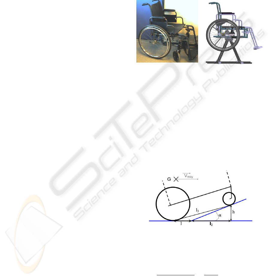
In order to keep close to reality we decided to base
our interface on a real wheelchair (Figure 1a), which
has been instrumented and in part redesigned (Figure
1b). The original wheelchair has been fixed on a
tubular framework, which supports it and assures a
good stability. This framework can be easily taken
apart and is then easily transportable. A rotating
joint placed a few centimetres in front of the wheel’s
axle (just below the estimated static centre of
gravity) supports the wheelchair and allows it to lean
forwards and backwards to simulate shocks and
displacements on a sloping ground.
Figure 1a: Original
wheelchair used as base.
Figure 1b: CAD model of
mechanical framework.
An electrical jack fixed between the framework
and a horizontal tube in front of the wheelchair
controls this degree of freedom. It is driven by a DC
motor supplied by a PWM signal to be controlled in
position. An external angular sensor is placed by the
side of this joint to measure the pitch orientation of
the wheelchair.
The actuator has been sized according to the
angular acceleration and velocity experienced by the
wheelchair when it moves on a slope (10% max)
with maximal speed of 10 km/h (Equation
1)(Figure2).
Figure 2: Slope.
With V
moy
, the initial horizontal velocity, α the
angle of the slope, l
3
the wheelbase, h the length to
control.
2
2
3
2
2
3
.4]
8
tan
1.[
.2
sin.tan.
)(
−
••
=+−= smm
l
v
lh
moy
α
αα
Equation 1
In addition to slopes, shocks to simulate can be
provided by lateral contact against walls. However
to feel realistic lateral contact should represented by
ICINCO 2006 - ROBOTICS AND AUTOMATION
428
a free motion of the user’s legs. Indeed the user’s
legs behave like seismic mass that undergoes a
lateral acceleration or deceleration. To carry out this
controlled mobility, it would be necessary to add a
yaw degree of freedom, which makes the interface
much more complex. In our application, the fine
perception of lateral shocks close to reality is not
necessary, which is why we decided to use a
metaphor to represent them. Vibrators fixed on tubes
each side of the wheelchair work and complete the
electrical jack to make user feel the side on which
the shock happened. Vibrators are based on small
DC motors that turn an eccentric for 50 ms. During
the implementation phase, vibrators were not judged
as necessary because the visual rendering always
gave enough information about the contact location.
Therefore vibrators were not always used
afterwards.
3.2 Wheels
The wheels are certainly the most delicate part to
design according to our final goal because they are
the main parts for user to interact with and move in
the VE as he/she wants. Indeed these parts work in
driving mode to control the motion in VE and work
also in sensorial to give feedback to user.
As mentioned above, we wanted to make the
user feel a force feedback close to the real one to
understand difficulty and strenuousness at a real
level. The tangential user force applied on the
circular handle of the wheel was estimated
experimentally at about 150 N. In order to supply a
high force (50 N.m torque) during shocks or starts,
we could use either a high power motor or an
irreversible system. Mechanical implementation
(bulk) and control of a high power motor would be
delicate at low speed for example, which is why we
decided to choose a transmission power chain with a
reducing ratio close to the threshold of
irreversibility. A 100 Watts DC Motor with a 1:30
reducer ratio was chosen to drive each wheel
independently. Each of them is supplied by a PWM
signal and drives the gears of the wheel and another
gear to drive an incremental encoder. These sensors
provide the feedback signals in order to control the
direction and velocity of the wheels. Motors and
sensors are placed under the seat to maintain the
compactness of the wheelchair and to make it easy
to link the equipment to the power supply or the
main PC.
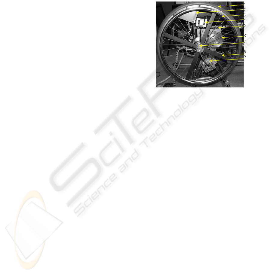
To get data about the user interaction with the
wheels, the joins between handrails and wheels have
been instrumented. The force or torque measuring
device is very important to provide information
about the interaction between the user and the
interface. As it is not necessary to measure
accurately the actual user’s force applied to the
handrail, we decided to employ a S-shape force
sensor to obtain an image of the tangential force
vector. Like that, handrails now equipped with
spokes can rotate around the main axle and are fixed
on the wheels thanks to the S-shape force sensor
(figure 3).
1 : Tire 2 : Force sensor support
3 : Handrail 4 : Force sensor
5 : Motor support 6 : Driving gear
7 : Slipring brush 8 : Circular handle spoke
9 : Sensor electronics
Figure 3: Wheel subsystem.
The wires of the force sensor and its conditioner
are placed on the wheel and cross the main axle
which is now drilled from tip to tip. The slip-ring
brush on the tip axle assures a good connection
between the rotating parts and fixed part of wires.
The wheel subsystem provides force data to the
Central Unit which computes according to the actual
mechanical parameters of virtual environment the
theoretical value of the velocity applied on each
wheel. This procedure describes the control method
used to drive our wheelchair interface as a driving
and sensorial interface. With its irreversibility
characteristic, this wheel functions as a force
feedback joystick. This mechanical particularity can
supply a high force feedback when a shock happens.
Presently the velocity is controlled by a PID
controller, which dynamic enough to simulate
shocks (Katsura, 2004). The control law is quite
simple because it satisfies well our immersion
criteria (difficulties, tiredness). Moreover shocks
against walls are not very strong and the virtual
wheelchair would not bounce a lot against this kind
of obstacle. Finally during a shock, the electrical
A SPECIFIC LOCOMOTION INTERFACE FOR VIRTUAL REALITY - Design of a Wheelchair Type Haptic
429
jack which control the pitch of the interface will be
preponderant in comparison with other actuators.
3.3 Data Acquisition
Data from all sensors are collected by a NI Data
Acquisition Board PCI 6024E plugged on a
dedicated PC. The latter has to control all input /
output signals related to the sensors and actuators on
the wheelchair.
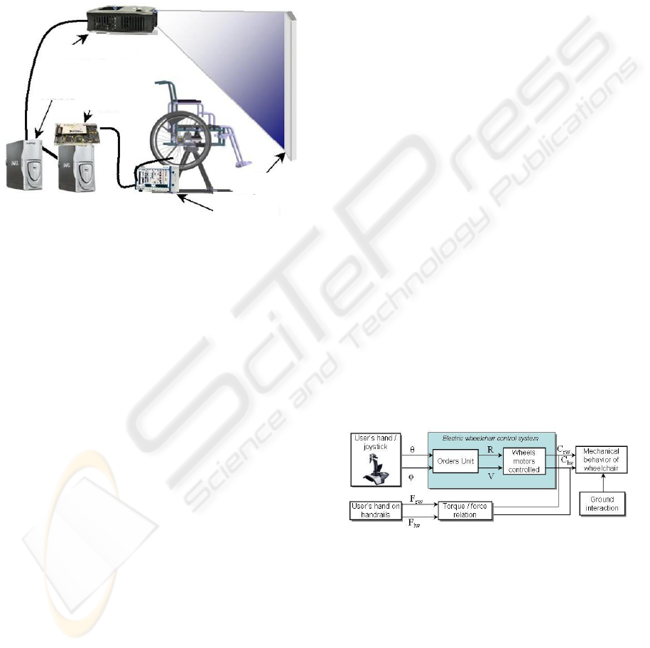
Figure 4: Global architecture.
Input signals are filtered and shaped by an
electronic rack before supplying the DAQ board.
Figure 4 illustrates the global chosen architecture
composed with 2 PCs. The main PC computes the
virtual world, receives data from the wheelchair
sensors and transmits orders to actuators according
to different control laws. This PC has a wider rule to
treat the virtual environment which will be detailed
below.
Two main power supplies are used to supply
firstly the control part (sensors) and secondly the
powerful devices such as actuators (wheel motors
and electrical jack). For security, an emergency
button is placed near the user’s left hand to power
off all actuators. Those are irreversible and so stop
very quickly when power is shut down.
4 MOTION GENERATION
Motion generation is computed by the Virtual
Environment Simulator (Flatland) which is
presented in the next section.
4.1 Mechanical Behavior
The kinematics and dynamics of our interface are
modelled to provide the interface motion by
including user’s forces, and the reaction of the VE.
Indeed the contact between the wheel and ground
must be well defined to allow a complete immersion
with a good level of realism and so avoid primarily
any disturbances or delays between the visual
rendering and the touch. Note we want to reproduce
the difficulties of motion and this is not limited to
experiencing a scene with obstacles and potential
shocks. Indeed we wanted to highlight that keeping a
desired direction while moving on a banked ground
is particularly difficult and need skill and force from
the wheelchair user.
That is why the user’s forces and effect of the
ground on the wheels have been reduced to a
dynamic torsor applied on the median point of
contact on the ground. Thus by taking into account
the mass distribution, the nature of contact between
wheel and ground, and external actions from user
and ground, we modeled a banking torque which
disturbs the direction of motion. Also the difficulties
involved in a simulating banked ground are rendered
not by roll change of wheelchair interface but by
disturbing the motion direction and via a disturbing
torque applied differently to each wheel. In
freewheel on banked ground, the wheelchair, under
the banking torque action, tends to be oriented in the
direction of the bank and so it can swing around this
direction if it started from an unspecified orientation.
4.2 Joystick Behavior
A joystick driving mode is necessary to simulate the
behavior of an electric wheelchair in a VE. As for
the mechanical model, a dedicated model has been
proposed to simulate the joystick functioning and the
whole electric wheelchair control unit.
Figure 5: Architecture of electric wheelchair.
With φ and θ angles of both joystick’s dof, R and
V respectively the curve radius and the velocity of
the desired trajectory, Crw and Clw respectively
torques on right and left wheels, Frw and Flw
respectively forces on right and left wheels.
The mechanical behavior of the wheelchair is
supplied either by joystick data or user’s force data
depending upon whether the electrical mode or
mechanical mode was chosen (figure 5).
Videoprojecto
r
Screen
Electronic
rack
PC
+
DA
Q
board
Main
PC
ICINCO 2006 - ROBOTICS AND AUTOMATION
430
Both modes of control simulate the actual
behaviors well and are implemented in the VE as
described just below.
5 IMPLEMENTATION
The VE runs in Flatland which is a simulator of
virtual world created and developed by LISMMA
laboratory (Yushchenko, 2003). This simulator is
designed to be connected to all kinds of behavioral
interface like haptics or locomotion interfaces for
VR (Dupuis, 2005). Flatland uses Parallel Virtual
Machine libraries to distribute computations on the
PC cluster. The main PC presented above runs
Flatland and controls another PC that tracks eye
movement. This architecture is interesting to
compute heavy tasks such as that which controls the
video rendering.
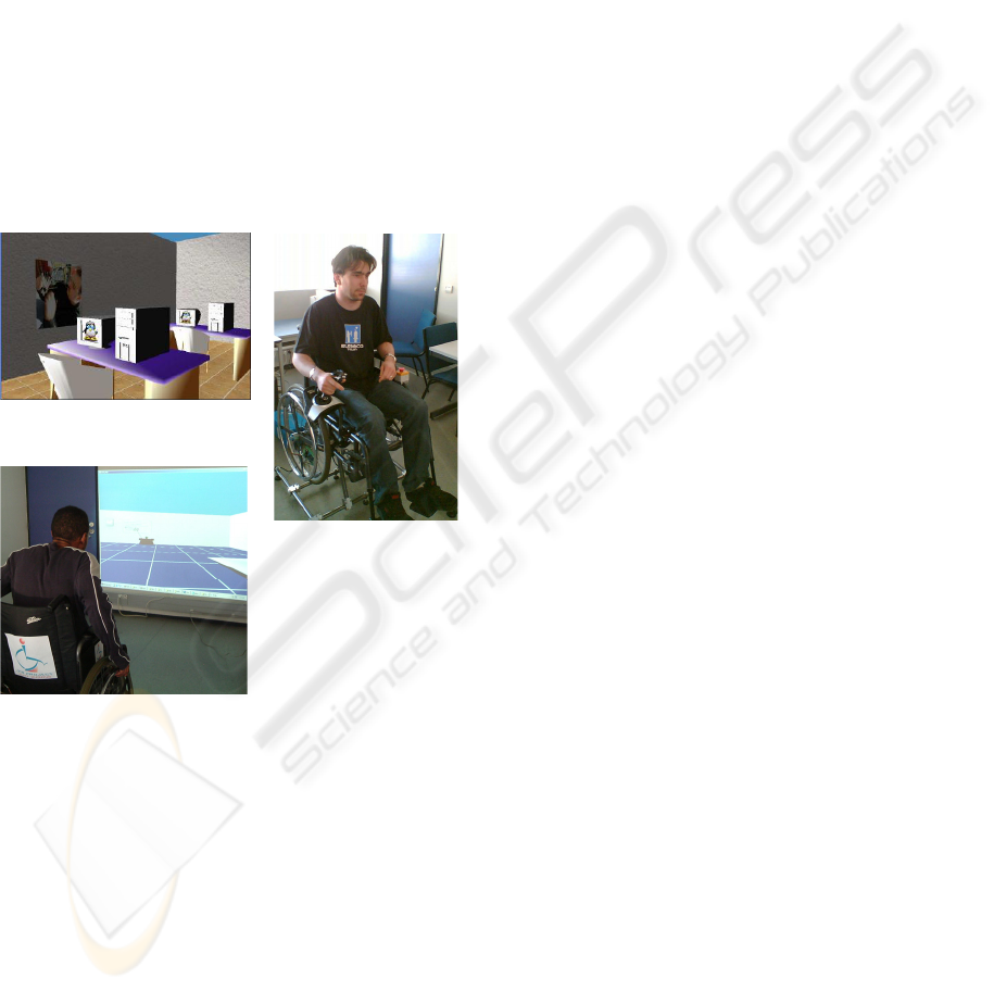
Figure 6a: A virtual room.
Figure 6b: Electric
wheelchair mode.
Figure 6c: Mechanic
wheelchair mode.
Different types of environment can be
implemented for example like a classroom (figure
6a) or a hall equipped with wheelchair access (figure
6c). All VEs can be explored virtually with any
modes of functioning (figure 6b).
Many experiments have been carried out to
evaluate the degree of realism. Globally, it appears
that the wheelchair interface is very intuitive and
natural. Indeed the user’s action are similar than
those he/she would do in actual reality. Sensorial
feedbacks are immediately understood by the user
and so he/she can focus on the main task, which is to
move as he/she wants.
Furthermore, the difficulty and energy required
to move is simulated well because the motion within
a virtual room is felt as a real effort when the
interface is used in mechanic wheelchair mode.
A virtual corridor is useful to evaluate the user’s
skill and difficulties in building design while the
interface was controlled as an electric wheelchair.
6 CONCLUSION
The work presented here, widely supported by
SMI/MIT students from Supmeca and ISEN
institutes, achieves its original goals in order to help
building designers in their task.
The locomotion interface wheelchair-type we
have designed is effective in highlighting the
difficulties which can be experienced by disabled
wheelchair users. Mechanical and electric
wheelchairs were implemented and both correctly
simulate the actual behaviour. This study illustrates
the great interest of the generic interface feature in
order to connect any kind of locomotion interface to
Flatland.
The next step of this research is to implement a
spatial sound feedback to upgrade our present stereo
rendering. Indeed within a noisy hall or close to a
train in a station for example, noise can easily be
considered as a lack of comfort or more a hindrance
to catch information.
REFERENCES
Harrison C.S, Grant M., Conway B. 2004. A Haptic
Interfaces for Wheelchair Navigation in the Built
Environment. Presence: Teleoperators & Virtual
Environments, Volume 13, Number 5, October 2004,
pp. 520-534(15)
Fuchs, P, Moreau, G 2003. Le traité de la Réalité
Virtuelle. Presses de l'école des mines - 10/2003. 540
p. ISBN: 2-911762-47-9
Dupuis, Y., Anthierens, C., Impagliazzo, J.L.,
Yushchenko, L. 2005. Design of a sensorial and
driving locomotion interface. 16th IFAC world
congress, Pragues, July, 4-8th, 2005.
Yushchenko, L, Impagliazzo, J-L, Anthierens, C. 2003
Design of an advanced scientific simulator equipped
with immersive interfaces. Application to a
micromanipulation task. Mecatronics'2003, Tokyo
Denki university, Hatoyama, Japan, September 9-11,
2003, pp 338-43.
Katsura, S., Ohnishi, K., 2004. Human Cooperative
Wheelchair for Haptic Interaction Based on Dual
Compliance Control. IEEE Transactionc on industrial
electronics, vol. 51, N°.1, February 2004, pp221-228.
A SPECIFIC LOCOMOTION INTERFACE FOR VIRTUAL REALITY - Design of a Wheelchair Type Haptic
431
