
MANAGING CONTROL ARCHITECTURES DESIGN PROCESS
Patterns, Components and Object Petri Nets in Use
Robin Passama
*,**
, David Andreu
*
, Christophe Dony
**
, Thérèse Libourel
**
*
Robotics and
**
Computer science departments, LIRMM,161 rue Ada ,Montpellier ,France
Keywords: Software Components, Control Architecture pattern, Integration, Reuse, Object Petri Nets.
Abstract: The paper presents a methodology for the development of robot software controllers, based on actual
software component approaches and robot control architectures. A proposed control architecture pattern,
useful for analysis and integration of expertise during design process is presented. A dedicated component-
based language, focusing on reusability and upgradeability of controller architectures parts, is used to design
and to implement software architectures.
1 INTRODUCTION
Robots are complex systems whose complexity is
continuously increasing as more and more
intelligence (decisional and operational autonomies,
human-machine interaction, robots cooperation, etc.)
is embedded into their controllers. This complexity
also depends, of course, on the mechanical portion
of the robot that the controller has to deal with,
ranging from simple vehicles to complex humanoid
robots. These two portions of a robot, its mechanical
part (including its sensors and actuators) and its
control logic, are intrinsically interdependent.
Nevertheless, for reasons of reusability and
upgradeability, the controller design should separate,
as far as possible, these two aspects: the
functionalities that are expected from the robot on
the one hand, and, on the other, the representation of
both the mechanical part that implements them, of
the environment with which it interacts. One current
limitation in the development of robot software
controllers is the difficulty of integrating different
functionalities into a same controller, as they are
often closely designed and developed for a given
robot (i.e., for a given mechanical part). Hence,
upgradeability and reusability are aims that are
currently almost impossible to achieve since both
aspects of the robot (control and mechanical
descriptions) are tightly merged. The reuse of
decision-making/control systems parts is also a big
challenge, because of the different approaches
(behavioral or hierarchical) that can be used to
design it.
We aim to provide a methodology that rationalizes
the development process of a robot software
controller in order to help overcoming these
limitations. We thus present the CoSARC
(Component-based Software Architecture of Robot
Controllers) development methodology based on:
actual component (Szyperski, 1999) and architecture
descriptions languages (Medvidovic & Taylor,
1997), approaches in software engineering and
control architectures design techniques in robotics.
CoSARC defines a process that guides developers
during analysis, design, implementation, deployment
and operation of a robot controller. Its structure is
based on two concepts: a controller architecture
pattern for analysis, presented in section 2, and a
component-based language, presented in section 3.
They cover design process life cycle from analysis,
to implementation. This paper concludes by citing
actual work on the CoSARC methodology.
2 ARCHITECTURE PATTERN
Robot control architectures are a widely studied
domain. Three categories of architectures have so far
emerged: hierarchical (Gat, E., 1997), behavioral
(Brooks R. et al, 1986) and hybrid, like ORCCAD
(Borrely & al., 1998), CLARATy (Volpe, R. et al.,
2001), AURA (
Arkin & Balch, 1997) and LAAS
architectures (Alami, R. et al, 1998). Our
architecture pattern follows an hybrid approach. It
defines a generic organization by outlining the
entities involved in the controller’s actions/reactions,
by defining layers hierarchization properties and by
matching entities and layers (Fig. 1).
223
Passama R., Andreu D., Dony C. and Libourel T. (2006).
MANAGING CONTROL ARCHITECTURES DESIGN PROCESS - Patterns, Components and Object Petri Nets in Use.
In Proceedings of the Third International Conference on Informatics in Control, Automation and Robotics, pages 223-228
DOI: 10.5220/0001208802230228
Copyright
c
SciTePress
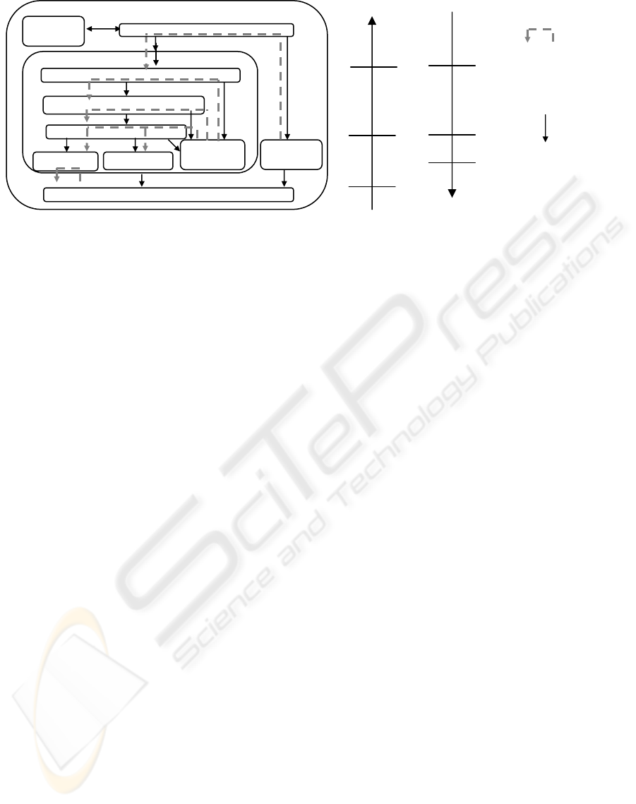
The central abstraction in the architecture pattern
is the Resource. A resource is a part of the robot’s
intelligence that is responsible for the control of a
given set of independently controllable physical
elements. For instance, consider a mobile
manipulator robot consisting of a mechanical arm
(manipulator) and a vehicle. It is possible to abstract
at least two resources: the
ManipulatorResource which
controls the mechanical arm and the
MobileResource
which controls the vehicle. Depending on
developer’s choices or needs, a third resource can
also be considered, coupling all the different
physical elements of the robot, the
Mobile-
ManipulatorResource
(the robot is considered as a
whole). The breaking down of the robot’s
intelligence into resources mainly depends on three
factors: the robot’s physical elements, the
functionalities the robot must provide and the means
developers have to implement those functionalities
with this operative part.
A resource (cf. Fig. 1) corresponds to a sub-
architecture decomposed into a set of hierarchically
organized interacting entities. Presented from
bottom to top, they are (regarding the
ManipulatorResource):
A set of Commands. A command is in charge of
the periodical generation of command data to
actuators, according to given higher-level
instructions (often setup points) and sensor data;
commands often encapsulate control laws. The
actuators concerned belong to the set of physical
elements controlled by this resource. An example of
a command is the
JointSpacePositionCommand (based
on a joint space-position control law that is not
sensible to singularities, i.e. singular positions linked
to the lining up of some axis of the arm).
A set of Perceptions. A perception is responsible
for the periodical transformation of sensor data into,
potentially, more abstract data. An example of a
perception is the
ArmConfigurationPerception that
generates the data representing the configuration of
the mechanical arm in the task space from joint
space data (using the arm’s direct geometric model).
A set of Event Generators. An event generator
ensures the detection of predefined events
(exteroceptive or proprioceptive phenomena) and
their notification to higher-level entities. For
example the
SingularityGenerator is able to detect the
singularity vicinity (using equations describing the
singular configurations).
A set of Actions. An action represents an activity
that the resource can carry out. An action is in
charge of commutations and reconfigurations of
commands. An example of an action is the
ManipulatorContactSearchAction, which uses a set of
commands (commutation of control laws).
A set of Modes. Each Mode describes one resource
behavior and defines the set of orders the resource is
able to perform. For example, the
MobileResource has
two modes: the
MobileTeleoperationMode using which
the human operator can directly control the vehicle
(low-level teleoperation), and the
MobileAutonomous-
Mode
in which the resource is able to accomplish
high-level orders (e.g. ‘go to position’). A mode is
responsible for the breaking down of orders into a
sequence of actions, as well as the scheduling and
synchronization of these actions.
A Resource Supervisor is the entity in charge of
the modes commutation strategy, which depends on
the current context of execution, the context being
defined by the corresponding operative portion state,
the environment state and the orders to be
performed. A robot controller architecture consists
of a set of resources (cf. Fig. 1) controlled by a
global supervisor. The global supervisor of a robot
controller is responsible for the management of
resources according to orders sent by the operator,
and events and data respectively produced by event
generators and perceptions. Each resource of a
robot controller interacts with Input/Output
controllers. These I/O controllers are in charge of
periodical sensor and actuator-data updating.
Time constraints
Input/Output Controller
E
vent
Generator
1..*
*
1..*
1
Resource Supervisor
Mode
Action
Resource
Command
Perception
Event
Generator
1..*
1..*
1..*
1..*
*
1..1
M
ission
M
anager
1..1
1..1
Robot Controller
Reaction priority
low
medium
high
low
high
medium
Reactivity loop
Figure 1: Control architecture pattern (UML-like syntax), and layer hierarchization properties.
Control relationship
Global Supervisor
ICINCO 2006 - ROBOTICS AND AUTOMATION
224

Commands, event generators and perceptions of
resources interact with I/O controllers in order to
obtain sensor or to set actuator values.
Organization of Resources and robot controller
also follow a “hierarchical” approach. Each layer
represents a “level of control and decision” in the
controller activities. The upper layer incorporates
entities embedding complex decision-making
mechanisms like modes, supervisors and mission
manager. The intermediate layer incorporates
entities like control schemas (commands), observers
modules (event generators, perceptions) and reflex
adaptation activities (inside actions). The lower
layer (I/O controllers) interfaces upper layers with
sensors, actuators and communication peripherals.
3 COMPONENT LANGUAGE
The CoSARC language is devoted to the design and
implementation of robot controller architectures.
This language draws from existing software
component technologies such as Fractal (Bruneton
& al., 2002) and Architecture Description
Languages such as Meta-H (Binns & al., 1996). It
proposes a set of structures to describe the
architecture in terms of a composition of cooperating
software components.
A software component is a reusable entity subject
to “late composition”: the assembly of components
is not defined at ‘component development time’ but
at ‘architecture description time’. The main features
of components in the CoSARC language are internal
properties, ports, interfaces, and connections. A
component encapsulates internal properties (such as
operations and data) that define the component
implementation. A component’s port is a point of
connection with other components. A port is typed
by an interface, which is a contract containing the
declaration of a set of services. If a port is ‘required’
(resp. ‘provided’), the component uses (resp. offers)
the services declared in the interface typing the port.
All required ports must always be connected
whereas it is unnecessary for provided ones. The
component’s internal properties implement services
and service calls, all being defined in the interfaces
typing each port of a component. Connections are
explicit architecture description entities, used to
connect ports. A connection is used to connect
‘required’ ports with ‘provided’ ones. When a
connection is established, the compatibility of
interfaces is checked, to ensure ports connection
consistency. The advantage of the “late
composition” is the improvement of the reusability
of components (more independent from each other
than objects), and of the modularity of architectures
(possible change of components and connections).
The CoSARC language defines four types of
components (presented below). Each of them is used
to deal separately with a specific preoccupation
during controller architecture design.
3.1 Representation Components
This type of component is used to describe a robot’s
“knowledge” as regards on its operative part, its
mission and its environment. Representation
components are used to satisfy the “real-world
modeling” preoccupation, but their use can be
extended to whatever developers consider as the
knowledge of the robot. They can represent concrete
entities, such as those relating to the robot’s physical
elements (e.g. chassis and wheels of a vehicle) or
elements of its environment. They can also represent
abstract entities, such as events, sensor/actuator data,
mission orders, control or perception computational
models, etc. When a developer wants to represent
the fact that a specific model is applied on a specific
(operative) part of the robot, it just has to connect
those two representation components: that
corresponding to the computational model with that
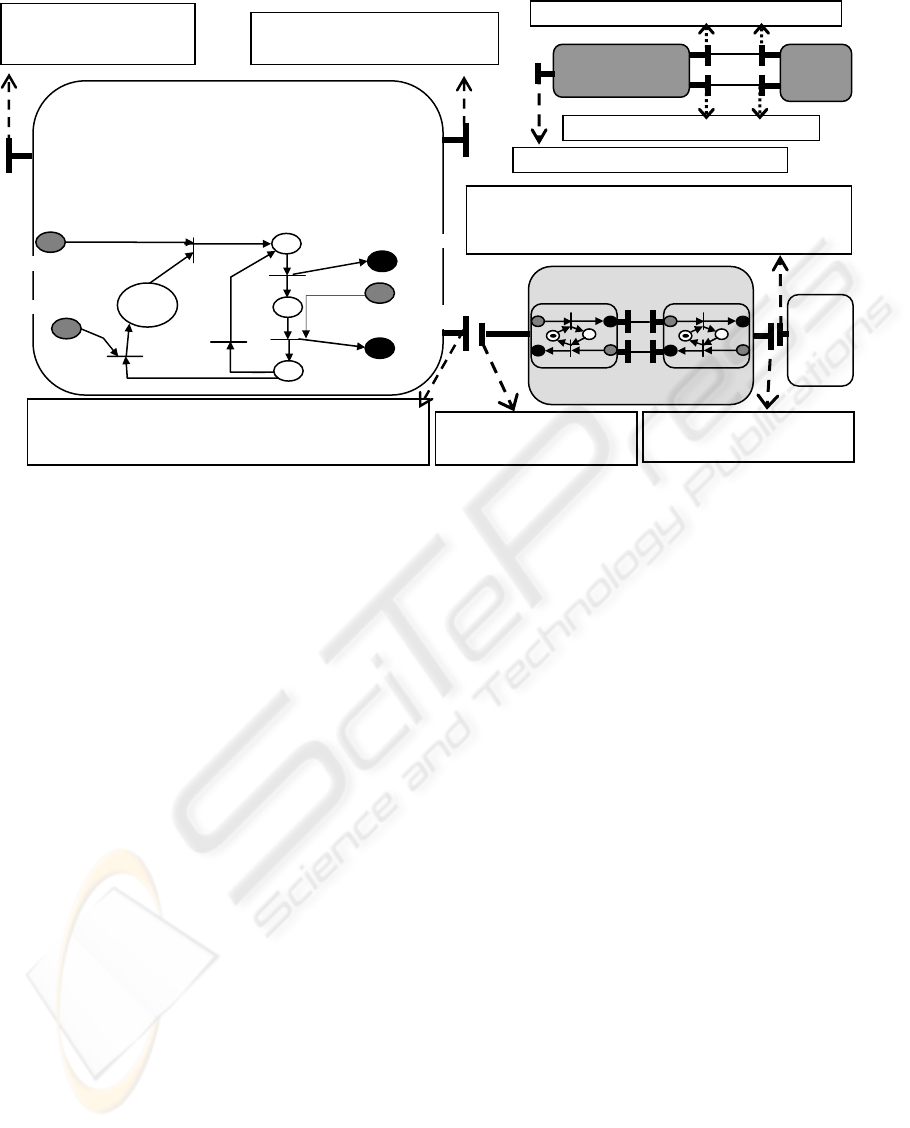
related to the operative part. For example, Fig. 2
illustrates how to apply a control law to a vehicle.
Representation components are ‘passive’ entities
that only act when one of their provided services is
called. They only interact according to a
synchronous communication model. Internally,
representation components consist of object-like
attributes and operations. Operations implement the
services declared in provided ports and they use
services declared in interfaces of required ports.
Representation components are incorporated and/or
exchanged by components of other types, such as
control components and connectors. Representation
components can also be composed between
themselves when they require services of each-other.
Indeed, a representation component consists of a set
of provided ports that allows other representation
components to get the value of its “static” physical
properties (wheel diameter, frame width, etc.) and/or
to set/get the current value of its “dynamical”
properties (velocity and orientation of wheels, etc.).
Fig. 2 shows a simple example of composition. The
representation component called
VehiclePosition-
ControlLaw
consists of:
- a provided port, typed by the VehicleActuators-
ValueComputation
, through which another component
(a control one for instance) can ask for a
computation of the actuator’s value to be applied.
- and two required ports. The first one is typed by
the
VehiclePhysicalPropertiesConsultation interface, the
second one by the
VehicleDynamicProperties interface.
These interfaces are necessary for the computation
MANAGING CONTROL ARCHITECTURES DESIGN PROCESS - Patterns, Components and Object Petri Nets in Use
225

as some parameters of the model depend on the
vehicle on which the corresponding law is applied.
The corresponding ports are provided by the
representation component
Vehicle. VehiclePosition-
ControlLaw
and Vehicle are so composed by
connecting the two required ports of the former with
the two corresponding provided ports of the latter.
3.2 Control Components
A Control Component describes a part of the control
activities of a robot controller. It can represent
several entities of the controller, as we decompose
the controller into a set of interconnected entities (all
being components), like for example: Commands,
Actions, Perception, Event Generators, Modes, etc.
A control component incorporates and manages a set
of representation components which define the
knowledge it uses to determine the contextual state
and to make its decisions. Control components are
‘active’ entities. They can have one or more
(potentially parallel) activities, and they can send
messages to other control components (the
communication being further detailed). Internal
properties of a control component are attributes,
operations and an asynchronous behavior.
Representation components are incorporated as
attributes (representing the knowledge used by the
component) and as formal parameters of its
operations. Each operation of a control component
represents a context change during its execution.
The asynchronous behavior of the control
component is described by an Object Petri Net
(OPN) (Sibertin-Blanc, 1985), that models its
‘control logic’ (i.e. the event-based control-flow).
Tokens inside the OPN refer to representation
components used by the control component. The
OPN structure describes the logical and temporal
way the operations of a control component are
managed (synchronizations, parallelism, concurrent
access to its attributes, etc.). Operations of the
control component are executed when firing OPN
transitions. This OPN based behavior also describes
the exchanges (message reception and emission)
performed by the control component, as well as the
way it synchronizes its internal activities according
to these messages (i.e. the control component’s
reaction according to the context evolution).
Fig. 2 shows a simplified example of a control
component behavior that corresponds to a command
entity, named
VehiclePositionCommand. It has three
attributes: its
periodicity, the Vehicle being controlled
and the applied
VehiclePositionControlLaw. The Vehicle
and the
VehiclePositionControlLaw are connected in the
same way as described in the top right corner of
Fig.2, meaning that the
VehiclePositionCommand will
compute the
VehiclePositionControlLaw based on the
parameters of the
Vehicle, at a given periodicity. Such
decomposition allows the adaptation of the
MobilePositionCommand to the Vehicle and the
VehiclePositionControlLaw used (i.e. the representation
components it incorporates). It is thus possible to
reuse this control component in different controller
architectures (for similar vehicles).
This control component’s provided port (cf. Fig. 2)
is typed by the interface named
VehiclePositionControl
that declares services offered (to other control
components) in order to be activated/deactivated/
configured. Its required ports are typed by one
interface each:
VehicleMotorsAccess which declares
services used to fix the value of the vehicle’s motors
and
MobileWheelVelocityandOrientationAccess which
declares services used to obtain the values of the
orientation and velocity of the vehicle’s wheels.
These two interfaces are provided by ports of one or
more other control components.
The (simplified) OPN representing the
asynchronous behavior of
VehiclePositionCommand
shown in Fig. 2, describes the periodic control loop
it performs. Grey and black Petri net places
respectively represent reception and transmission of
messages corresponding to service calls. For
example, the grey place
startExecution and the black
place
RequestVelAndOrient correspond to services
respectively declared in the
VehiclePositionControl and
the
VehicleWheelVelocityandOrientationAcces interfaces.
3.3 Connectors
Connections of control components are reified into
components named connectors (that allow the
assembly). Connectors contain the protocol
according to which connected control components
interact. It implements a protocol that potentially
involves message exchanges, synchronizations and
constraints. Once defined, connectors can be reused
for different connections into the control
architecture. This separation of the interaction aspect
from the control one, appears to be very important in
order to create generic protocols adapted to domain
specific architectures. One good practical aspect of
this separation is that it leads to distinguish
interactions description with control activities
description, whereas describing both aspects inside
the same entity type would reduce the reusability.
A connector has sub-components named roles for
attributes. A role has attributes, operations and an
asynchronous behavior corresponding to the
behavior that a control component adopts when it
plays this role in the protocol defined by the
connector. When a control component plays a role,
the asynchronous behavior defined by the role is
attached to its own behavior. For each role it
incorporates, a connector has one required, or one
ICINCO 2006 - ROBOTICS AND AUTOMATION
226
provided, port (associated to the role). Each
connector port is typed by an interface that defines
the message exchange allowed between the
connector and the control component to be
connected. A role implements the message exchange
between the port of the connected control
component and its (own) associated port, as well as
the message exchange with the other role(s) of the
connector (i.e. exchanges inside the connector). An
interface of a connector’s port (provided or required)
must be compatible with the interface of the control
component’s port to which it is connected (i.e.
compatibility of the ports). For example, the
VehicleWheelsVelocityAndOrientation-Access interface is
compatible with the role
Requester provided by the
connector
Request/Reply-Connection (Fig. 2). This
connector, named
Request/ ReplyConnection, describes
a simple interaction protocol between a
Requester
and a
Replier (the two roles of the connector). It
consists of two ports: one provided port typed by the
Requester interface and one required port typed by
the
Replier interface. The control component
assuming the
Requester role, sends a request message
to the control component assuming the
Replier role,
which then sends the reply message to the
Requester.
Constraints described in the OPN of roles ensure
that only one request will be sent by the
Requester
until it receives a reply, and that the
Replier will
process only one request until it sends the reply to
the
Requester. This connector can be used to
establish connections between different control
components, if the interaction to be described
corresponds to this protocol. To design our mobile
robot architecture, we defined different types of
connectors supporting protocols like
EventNotification
or
DataPublishing. Connectors being also modeled by
Petri nets, it allows the global Petri net of the
controller to be built (i.e. the model resulting from
the composition of all the asynchronous behaviors).
Thanks to this property, developers can analyze
inter-component synchronizations (checking of
deadlock absence).
3.4 Configurations
Once the control architecture (or part of it) has been
completely modeled, the result is a graph of the
composition of control components. The last type of
component, named Configuration, contains this
graph. It allows developers to incorporate a software
(sub)-architecture into a reusable entity.
Configurations can be used to separate the
description of Resources, or robot control
architectures (for independent robot description in a
multi-robot team project). At design phase, a
configuration can be considered as a control
component because it has ports that are connectable
via connectors. Ports of a configuration export ports
of control components that the configuration
contains (dotted lines, Fig.3). At runtime, any
connection to those ports is replaced by a
connection to the initial port, i.e. to that of the
concerned control component.
Figure 2: representation components (dark grey), control component (white), and connectors (light grey).
VehiclePositionControl
: Executor
In StartExecution()
In StopExecution()
VehicleMotorsAccess
: Sender
Out FixMotorsValues(MotorValue)
VehicleWheelsVelocityAndOrientationAccess
: Requester
Out RequestVelAndOrien()
In ReceiveVelAndOrient(Velocity, Orientation)
V
ehiclePositionCommand
Attributes:
int period;
VehiclePositionControlLaw law;
Vehicle v;
Operations: //state change and
//initialisation operations
Asynchronous Behaviour:
<law,v>
[period,∞]
FixMotors Value
T1
T2
T3
stopExecution
startExecution
VehicleWheelVelocityandOrientationAccess
: Replyer
In ReceiveVelAndOrientRequest();
Out SendVelAndOrient(Velocity,Orientation)
Requester
In sendRequest(any)
Out receivedReply(any)
Replier
Out ReceiveRequest(any)
In sendReply(any)
RequesterRole
ReplierRole
RequestReply Connection
RequestVelAndOrient
ReceiveVelAndOrient
V
ehicle
VehiclePosition
ControlLaw
VehiclePhysicalPropertiesConsultation
VehicleActuatorsValueComputation
Vehicle
I/O
control
VehicleDynamicPropertiesAccess
Interface
Por
t
MANAGING CONTROL ARCHITECTURES DESIGN PROCESS - Patterns, Components and Object Petri Nets in Use
227
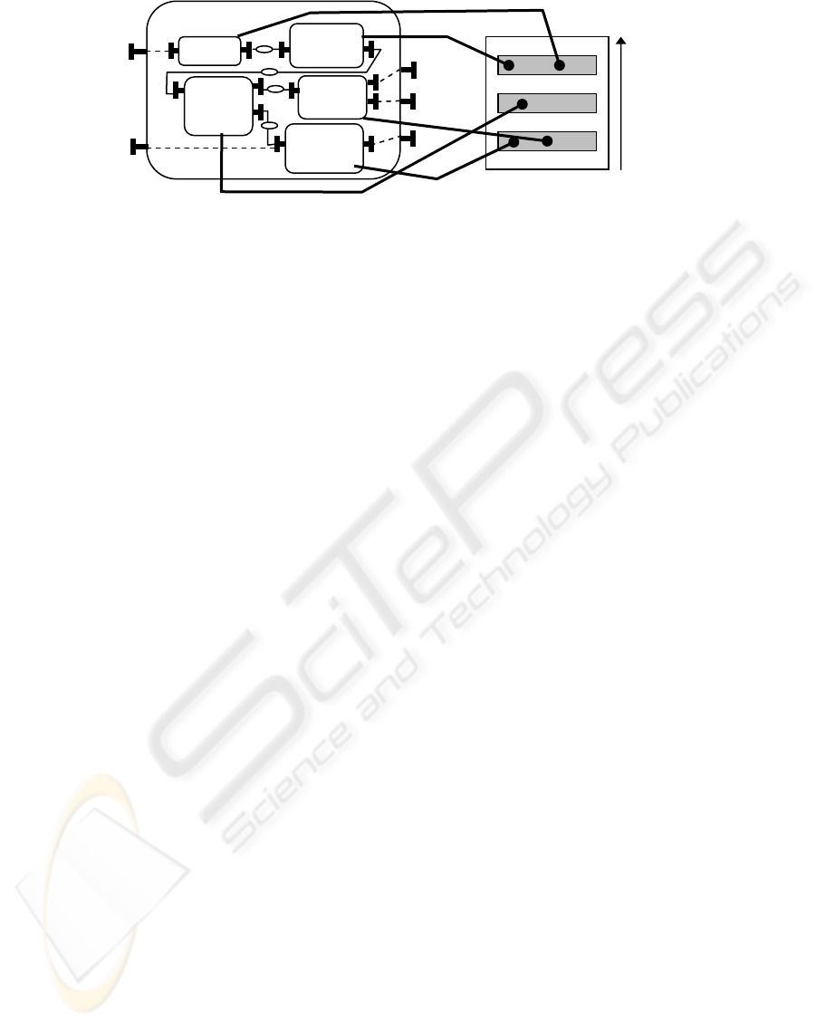
Fig. 3 shows an example of a configuration: the
MobileResource, corresponding to the sub-architecture
controlling the vehicle part of a mobile robot. It
incorporates the
MobileSupervisor, the Mobile-
AutonomousMode
, the MobileActionMoveTo-Position,
which interacts with the
Mobile-PositionCommand, and
the
MobileObstacleEvent-Generator. It exports the
provided port of the
MobileSupervisor and the required
ports of
VehiclePositionCommand and
VehicleObstacleEvent-Generator. Since a configuration
can contain others configurations, it allows
developers to describe the controller architecture at
different levels of granularity. When an architecture
is built following the pattern provided by the
CoSARC methodology, the ‘global’ configuration is
the Robot Controller. In the given example, the
MobileManipulatorController configuration incorporates
as many configurations as resources, i.e. the
ManipulatorResource and the MobileResource.
The CoSARC language provides containers to
describe the deployment of a configuration. They are
OS processes that execute a set of components. As
each container can represent a layer, they can be
used to manage the hierarchization.
4 CONCLUSION
We have briefly presented the CoSARC
methodology, which is devoted to improving
modularity, reusability and the upgradeability of
control architectures. It is specifically dedicated to
the integration of different aspects concerning robot
control (control laws, physical descriptions, action
scheduling, etc.), and can be seen as a framework
into which any standard can be used by developers
to represent their data, messages, services, etc.
Moreover, the CoSARC language has the added
benefit of relying on a formal approach based on
OPN formalism. This allows analysis to be
performed at the design stage itself, as analysis
cannot be ignored when designing the control of
complex systems. Future papers will present the
CoSARC language execution model.
REFERENCES
Alami, R. & Chatila, R. & Fleury, S. & Ghallab, M. &
Ingrand, F. (1998). An architecture for autonomy, Int.
Journ. of Robotics Research, vol 17, no 4, p.315-337.
Arkin, R.C. & Balch, T. (1997). Aura : principles and
practice in review. Technical report, College of
Computing, Georgia Institute of Technology, 1997.
Binns, P. & Engelhart, M. & Jackson, M. & Vestal, S.
(1996). Domain Specific Architectures for Guidance,
Navigation and Control, Int. Journal of Software
Engineering and Knowledge Engineering, vol. 6, no. 2,
pp.201-227, World Scientific Publishing Comp.
Borrely J.J. & al. (1998). The Orccad Architecture, Int.
Journ. of Robotics Research, vol. 17, no. 4, pp.338-
359.
Brooks, R. A. (1986). A robust layered control system for
a mobile robot. IEEE Journal of Robotics and
Automation, vol. 2, no. 1, pp.14-23.
Bruneton, E. & Coupaye, T. & Stefani, J.B. (2002).
Recursive and Dynamic Software Composition with
Sharing, Proc. of the 7th Int. Workshop on Component-
Oriented Programming at ECOOP02, Malaga, Spain.
Gat, E. (1997). On three-layer Architectures, A.I. and
mobile robots, D. Korten Kamp et al. Eds. MIT/AAAI
Press, RR. N°3552, 1997.
Medvidovic, N. & Taylor, R.N. (1997). A framework for
Classifying and Comparing Software Architecture
Description Languages, in Proc. of the 6th European
Software Engineering Conference, Springer-Verlag,
pp. 60-76, Zurich, Switzerland.
Sibertin-Blanc, C. (1985). High-level Petri Nets with Data
Structure, in Proc. of the 6
th
European workshop on
Application and Theory of Petri Nets, pp.141-170,
Espoo, Finland.
Szyperski, C. (2003). Component Software: Beyond
Object Oriented Programming, Addison-Wesley.
Vehicle
Autonomous
Mode
Action
Vehicle
Move To
Position
Vehicle
Position
Command
Vehicle
Obstacle
Event Generator
M
obile Resource
Mobile
Supervisor
Containers
priority
Control component placemen
t
Figure 3: description of the Mobile Resource with a configuration and description of its deployment.
Processing node
ICINCO 2006 - ROBOTICS AND AUTOMATION
228
