
EYE AND GAZE TRACKING ALGORITHM FOR
COLLABORATIVE LEARNING SYSTEM
Djamel Merad
LIRIS laboratory
Stephanie Metz
ICAR Laboratory
Serge Miguet
LIRIS Laboratory
Keywords:
Head tracking, Pattern recognition, Machine vision.
Abstract:
Our work focuses on the interdisciplinary field of detailed analysis of behaviors exhibited by individuals dur-
ing sessions of distributed collaboration. With a particular focus on ergonomics, we propose new mechanisms
to be integrated into existing tools to enable increased productivity in distributed learning and working. Our
technique is to record ocular movements (eye tracking) to analyze various scenarios of distributed collabora-
tion in the context of computer-based training. In this article, we present a low-cost oculometric device that
is capable of making ocular measurements without interfering with the natural behavior of the subject. We
expect that this device could be employed anywhere that a natural, non-intrusive method of observation is
required, and its low-cost permits it to be readily integrated into existing popular tools, particularly E-learning
campus.
1 INTRODUCTION
The principle of the oculometry is to measure the po-
sition and orientation of the eye of a subject as he
looks at a computer monitor. A software program,
which knows what is displayed on the monitor at what
particular instant, is able to determine what the sub-
ject had been looking at for any specified instant. For
many years, this technique has been used by psychol-
ogists to study behavioral responses to images, but
more recently, it has spread other domains such as
that of ergonomicists and Web masters. (Duchowski,
2002) provides an excellent survey of eye tracking ap-
plications in several information processing tasks. In
the case of analysis of the relationship between image
observation and cognitive response, we can quote for
example: the inspection of visual scenes (Henderson
and Hollingworth, 1998), visual Inspection (Reingold
et al., 2002), industrial engineering and human fac-
tors (Anders, 2001). But in the last few years, this
technique has been applied to determine the usabil-
ity of Web, and to determine why some web sites are
more effective than others (Sibert and Jacob, 2000).
This is a direct consequence of the development of
information technologies and communication.
Our work will relate to find precise oculometric
indicators that manifest during distributed computer
based training. We prescribe a control environment
where two geographically dispersed interlocutors en-
gaged in collaborative work via face-to-face video
conferencing. Each interactive station has a camera
that captures images of the subject’s faces and eyes
as movements occur and words are spoken. As the
collaboration progresses, we collect indicators which
will allow us to know, for each instant, what is con-
sulted by the interlocutors and for what type of inter-
actions. Thus, it will be necessary to synchronize the
verbal interactions with the glances of the subjects at
each instant of collaborative activity.
Previous work (A.Corbel et al., 2003), (Baker et al.,
2002) have made it possible to enumerate the types of
interactions observed at the instances during collabo-
ration using tools that allow the mutual construction
of a common conceptual representation of the subject
matter being discussed by the collaborators. In addi-
tion, tools that facilitate this type of activity have been
developed. In particular, DREW makes it possible to
collaborate and jointly synthesize knowledge through
primitives such as the catalogue, white board, a text
tool, an argumentative graph. These various studies
are based on the analysisof verbal corpora (catalogue)
and argumentative graphs. They do not make it pos-
326
Merad D., Metz S. and Miguet S. (2006).
EYE AND GAZE TRACKING ALGORITHM FOR COLLABORATIVE LEARNING SYSTEM.
In Proceedings of the Third International Conference on Informatics in Control, Automation and Robotics, pages 326-333
DOI: 10.5220/0001207503260333
Copyright
c
SciTePress
sible to pin-point the specific events that initiate an
interaction for mutual knowledge dissemination. In-
deed, the interlocutor does not always refer verbally
to the information which enabled him to find such so-
lutions. So if the ultimate goal is to help the interlocu-
tors in their collaboration, it is necessary to character-
ize the chronological process of mutual transfer and
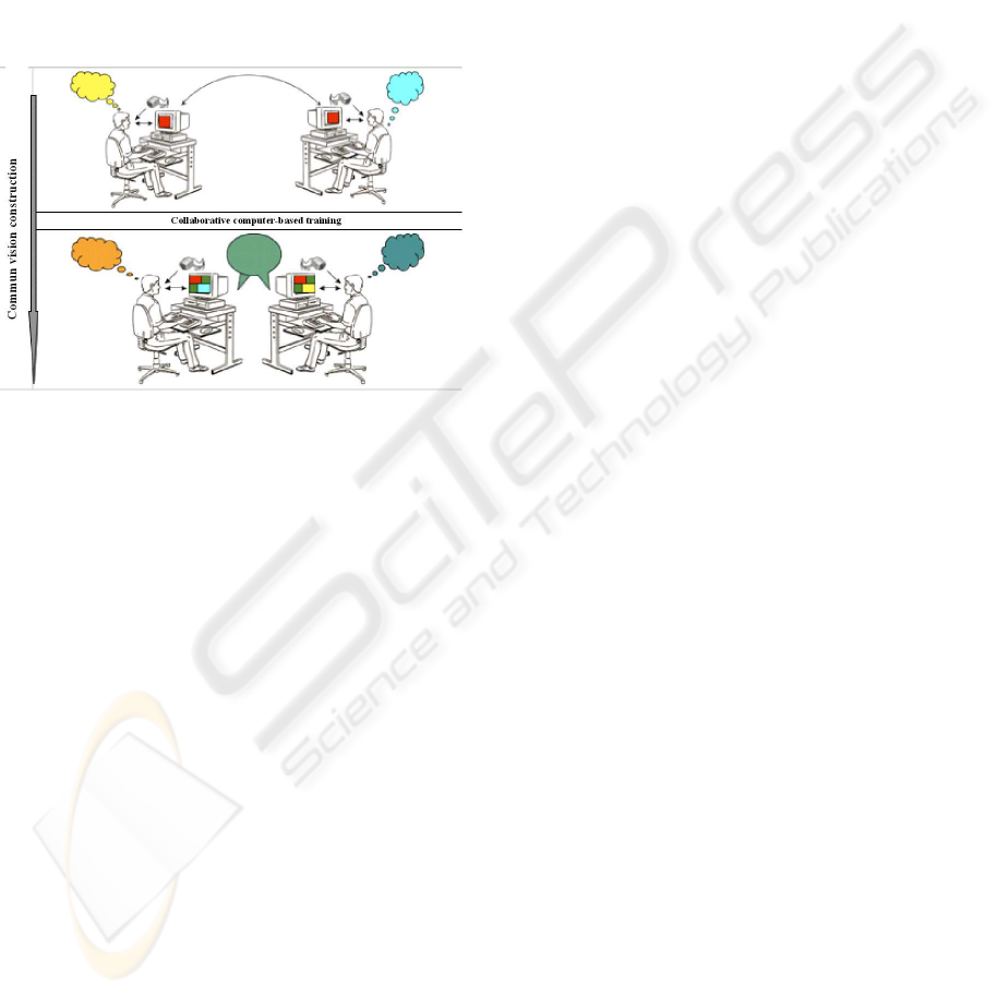
assembly of knowledge. For example, if one notes by
oculometry that an interlocutor seeks information on
the screen to argue, it would seem most appropriate
that assistive action would immediately present this
information centrally on the screen (figure 1).
Figure 1: collaborative task.
Several techniques to determine what assistive ac-
tion to take during the follow-up of a glance exist.
During last decades, these techniques gained much
in precision, which makes their fields of application
very broad. On the other hand, no instrument can be
perfect in a situation where none satisfies all the re-
quirements.
We can classify the techniques currently developed
in three groups, according to the degree of contact
with subject (Collewijn, 1999), (Glenstrup and Niel-
son, 1995).
• Techniques based on the reflection of a luminous
ray on the cornea.
• Techniques based on the application of a special
contact lens.
• Techniques of electro-oculography.
We point out that tools based on corneal oculomet-
ric reflection are the most used. These techniques are
those which present more comfort to the subjects, do
not require the presence of specialists (ophtalmolo-
gist) and, under good experimental conditions, give
precise results. We find on the market two types
of systems using corneal reflection: oculometer with
helmet (camera placed on the head) and oculome-
ter without helmet (camera placed on the monitor).
The oculometer with helmet is largely used because it
is adaptable and usable in several situations (reading
on dashboard, reading on monitor, subject moving...).
For this reason, practically all the companies have de-
veloped a model whose general principle is the same.
However for our purposes, we will not be able to use
this apparatus because the helmet is not comfortable
and will obviously interfere with the subject.
The oculometer without helmet makes it possible
to track in real time the movements of the eye using a
light-emitting diode (LED) coupled with camera de-
vice placed under the monitor. This tool is especially
adapted to work on computer displays. The first ap-
paratus of this type uses a head-rest to limit the field
of movement of this one. This constraint makes diffi-
cult its use for long-lasting experiments, as it results
in muscle fatigue. More recently we have seen pas-
sive devices that make no contact with the subject.
After seeing several demonstrations of these de-
vices, we have concluded that the most successful
is Tobbii. This apparatus has the advantage of be-
ing fast and easy to use and, more importantly, does
not place significant restrictions on the movements of
the subject during collaboration. However it is cost-
prohibitive, limiting its use as a general-purpose tool.
In short, several kinds of commercial products ex-
ist. These products are generally highly accurate and
reliable; however all require either expensive hard-
ware or artificial environments (cameras mounted on
a helmet, infrared lighting, etc). The discomfort and
the restriction of the motion affects the person’s be-
haviour, which therefore makes it difficult to measure
his/her natural behaviour. These limitations make
them unsuitable for our purpose. We have sought to
create a device that removes these limitations.
2 PROPOSED METHOD
The objective of our study is to correlate the men-
tal representation of exchanged information with the
verbal interactions that occur as the representation is
built. The oculometry must give indications on the
representations of each instant, and show the step-by-
step progression of development of the representation
as the collaboration proceeds.
First, we analyzed the most popular oculometric.
We noted the difficult problems to which they are
faced and that still have not been solved in a satis-
factory manner. We established that in the best con-
ditions, the system to develop must submit to the fol-
lowing requirements:
• No not hinder the head (or the body) movement.
• Not requires a direct contact with the user: nor hel-
met, nor lentils.
EYE AND GAZE TRACKING ALGORITHM FOR COLLABORATIVE LEARNING SYSTEM
327
• An affordable price.
• Good eye gaze localization.
• Enable a large vision field.
• Real time response.
• To be easy to use on a large palette of users.
• To be easily usable by the scientist and the user.
To solve this problem, much research has been di-
rected to non-intrusive gaze tracking in the past few
years (Wu et al., 2005), (Wang et al., 2003), (Zhu
and Yang, 2002), (Matsumoto and Zelinsky, 2000),
(Pastoor et al., 1999), (Kim and Ramakrishna, 1999),
(Toyama, 1998), (Stiefelhagen and Yang, 1997),
(Pomplun et al., 1994), (Baluja and Pomerleau, 1994).
These systems fall into two categories: analytical ap-
proaches and neural network approaches. A neu-
ral network based approach takes eye images as in-
put and learns patterns from examples. The reason
why they can achieve a higher accuracy is that they
take advantage of the pixel intensity information of
the whole eye image. Although neural network sys-
tems have achieved higher accuracy in offline evalua-
tions, few systems have been applied to real applica-
tions, because the trained neural network is too sensi-
tive to changes in users, lighting conditions, and even
changes within the user.
An analytical gaze estimation algorithm employs
the estimation of the visual direction directly from the
eye features such as irises, eye corners, eyelids, etc to
compute a gaze direction. If the positions of any two
points of the nodal point, the fovea, the eyeball center
and the pupil center can be estimated, the visual direc-
tion is determined. However, those points are hidden
in eyeball thus they will not be viewable without some
special equipment. The approach to solve this prob-
lem is to estimate the eyeball center from other view-
able facial features indirectly. These methods assume
that the eyeball is a sphere and the distances from the
eyeball center to the two eye corners is known (gen-
erally fixed to 13 mm). The eye corners are located
(for example by using a binocular stereo system) and
are then used to determine the eyeball center. They
also assume that the iris boundaries show circles in
the image and use Hough Transformation to detect
them. The center of the circular iris boundary is used
as the pupil center.
The drawback of these methods is the fact that the
eye model used is simplistic and is not adapted to all
persons. It is easy to see that the eyeball form is not a
sphere and it’s different for each person, also for sev-
eral pathological reasons (myopia, longsightedness,
...), the optic axis doesn’t pass by the eyeball center.
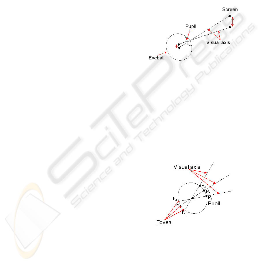
In this kind of methods, the accurate determination of
the eyeball center is very important. For example, if
the eyeball center is detected at 1mm from the real
position assuming that the eye radius is 13 mm, we
will find on a screen placed to 1m, an errors of 76.9
mm (figure 2).
Another drawback of this approach is the fact that
the accuracy of gaze tracking is greatly depends upon
the detection of the eye corners. For some people the
detection of corners is not made correctly because of
the eyelid form. Another difficult problem is the fact
that on particular head positions (with regard to cam-
era), the internal corner of the eye is occluded by the
nose, therefore eye gaze direction is not determined.
Figure 2: Error propagation.
For these reasons, we proposed to develop an
oculometer by a stereoscopic vision system without
eye corners detection. We determine the visual
direction by estimating the 3D position of the pupil
center named P by stereovision triangulation and the
eyeball center named C by an oculometric calibration
procedure exposed in section 2.1. We assume that
when changing the eye gaze, the eyeball rotates
around its center and this center is fixed with regard
to the head (figure 3).
Figure 3: Assumption.
The principle of this device presented in the fig-
ure 4 consists first in tracking the user head, followed
by the 2D eye zone localization. From this area, we
apply simple image processing in order to track the
pupil. The oculometric calibration enables us to find
the 3D eyeball center with respect to the head refer-
ence and finally, the intersection of the line formed by
ICINCO 2006 - ROBOTICS AND AUTOMATION
328
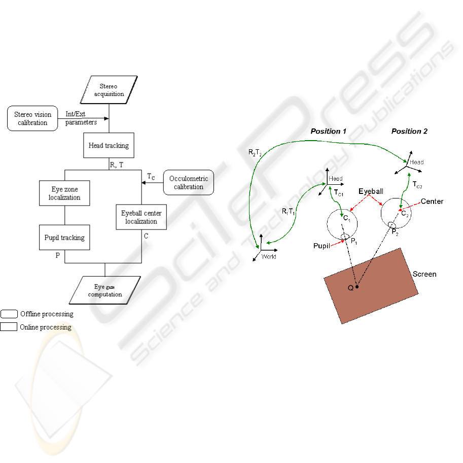
CP and the plan formed by the screen determines the
gaze point.
Head position is computed in real time by stereovi-
sion and while using some coded targets. This stage
is retailed in section 2.2 and the 3D pupil tracking is
described in paragraph 2.3.
In our system all localization measures are made
by a binocular system. We calibrated the two cameras
by Zhang’s method (Zhang, 1999). We obtained the
intrinsic and extrinsic parameters of each camera and
the left/right camera rigid transformation. The advan-
tage of using two cameras for eye tracking instead of
only one is that the absolute 3D position of the dif-
ferent features can be easily and precisely determined
by stereo matching of the characteristic points of both
eyes in the images.
Figure 4: Proposed Method.
2.1 Oculometric Calibration
The goal of this procedure is to determine the rigid ge-
ometric transformation (translation and rotation) en-
abling to find the position of the eyeball center C in
relation to the head landmark. This transformation is
only a translation T
c
.
For this procedure (figure 5), we know the 3D posi-
tion of a point Q on the screen as well as the 3D pupil
position with regard to a landmark associated to the
scene (world landmark). Moreover, we also compute
head/world transformation. One asks the user to stare
at a point on the screen, then we calculate world/head
transformation R
1
T
1
and we determine the 3D pupil
position/world landmark P
1
.
The user moves the head and stare at the same
point, we determine the second world/head transfor-
mation R
2
T
2
and we compute the second 3D pupil
position P
2
. We get the following equations :
Collinearity constraints:
C
1
= k
1
(P
1
− Q) + Q (1)
C
2
= k
2
(P
2
− Q) + Q (2)
We have also the following transformations:
C
1
= R
1
∗ T
c
+ T
1
(3)
C
2
= R
2
∗ T
c
+ T
2
(4)
We obtain an over-determined system with 12
equations and 11 unknown that we solve by the least
square method. Theoretically, we need only 1 point
and 2 head positions to localise the eyeball center, but
in practice and in order to improve the accuracy we
should take several points (or head positions).
Figure 5: Oculometric calibration.
2.2 Head Tracking
Many methods enabling real-time object pose compu-
tation in relation to the camera exist in the literature.
In the approach used for this application, the intrinsic
camera parameters are assumed to be known. In addi-
tion, the method requires finding the correct matching
between a set of 3D scene points and a set of 2D im-
age points. Thus, image features must be extracted.
Depending on the objective to reach and the pro-
cessing to apply on them, image features may be of
a very different nature. We can distinguish two main
families of image feature extraction approaches:
EYE AND GAZE TRACKING ALGORITHM FOR COLLABORATIVE LEARNING SYSTEM
329
- approaches which are based on searching a known
target in the scene,
- approaches which look for specific geometrical
primitives on the object to track.
Because of the hard constraint on computation time
in our context, we choose the first type of methods.
Indeed, instead of trying to recognize an object of the
real world, we prefer to detect the targets positioned
on it. Image processing algorithms can be optimized
for the detection of these targets of known geometry.
In addition, coded targets may contain specific fea-
tures which enable finding the semantic relationship
between observed objects and the a priori knowledge
about the real world.
Coded targets are widely used in augmented real-
ity systems. One of pioneering systems is the so-
called Matrix system proposed by Rekimoto (Reki-
moto, 1998), renamed later Cybercode (Rekimoto
and Ayatsuka, 2000). ARToolkit (Kato et al., 2000),
(Kato and Billinghurst, 1999) is a library which en-
ables rapidly creating augmented reality applications.
Unfortunately, performances of this freeware sys-
tem
1
have to be improved. For this reason, research
laboratories have developed their own applications
as ARTag (Fiala, 2005) which look like ARToolkit
much. InterSense society (Naimark and Foxlin, 2002)
has also developed its system coded target based sys-
tem. The later uses circular targets instead of square
targets generally used in prior systems. This system
was not the first one ((Cho and Neumann, 1998) de-
veloped a similar one in 1998) but it is considered as
the most performing.
Our goal is to rapidly and accurately detect and
localize the user head. That is why we opted for a
square target based system.
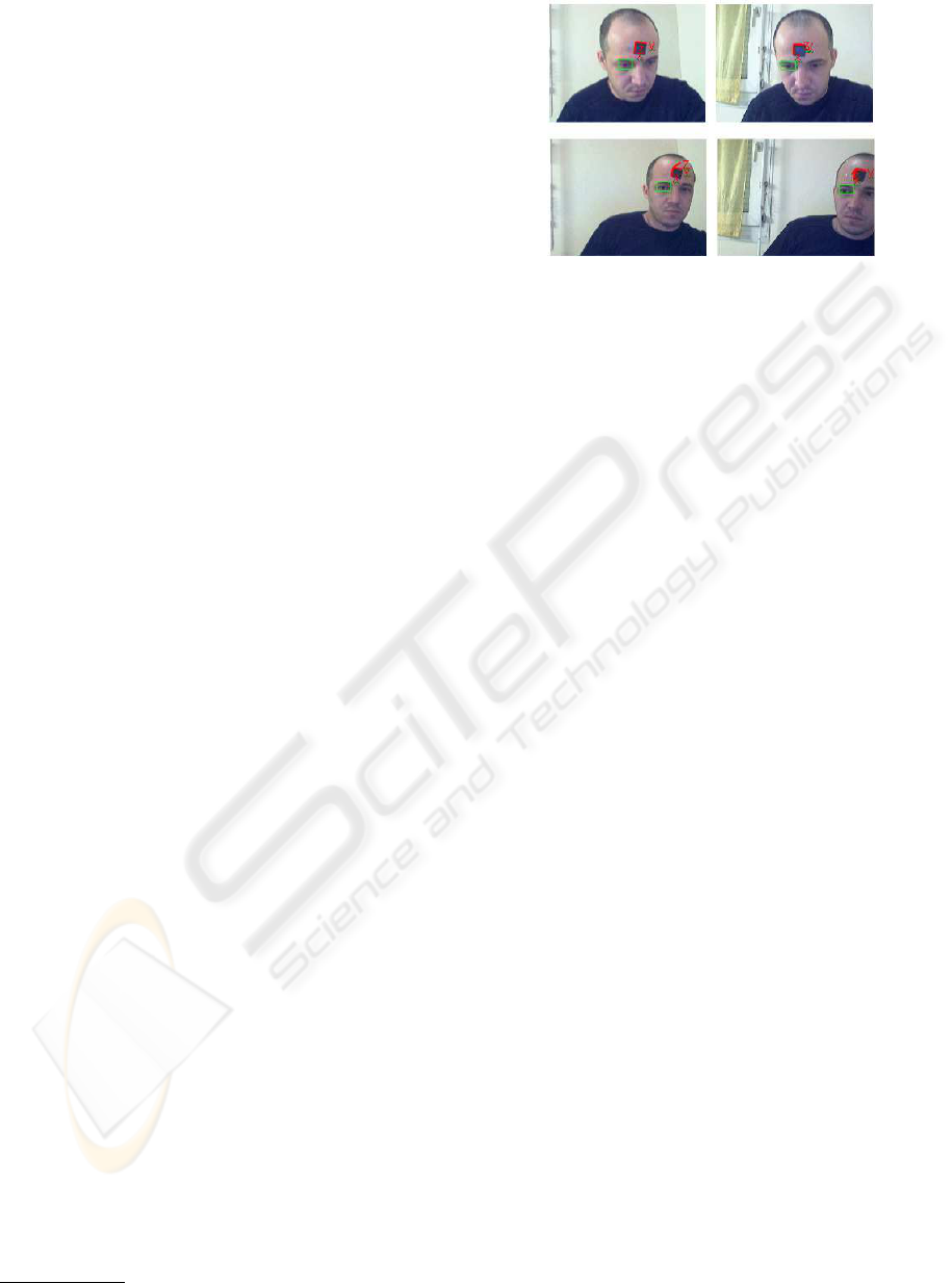
The processes used to achieve head detection and
localization are the following:
- contrast enhancement,
- image binarization,
- connex components analysis for black image area
detection,
- high curvature points detection,
- point index reading using white points of the target
corners,
- matching target corners which have the same in-
dex,
- head pose computation.
Some results are represented in the figure 6, where
the head landmark and the eye region are superim-
posed in the image.
1
http://www.hitl.washington.edu/artoolkit/
Figure 6: Head and eye tracking.
2.3 Pupil Tracking
The eye gaze determination algorithm cited above as-
sumes that the iris boundaries show circles in the im-
age and used Hough Transformation to detect them
(after edge detection). The center of the circular iris
boundary was used as the pupil center.
We have tried to use the same procedure and we
got some bad results, therefore we can state that this
approach has several drawbacks:
- In a natural behavior the eye is naturally mid
closed, it is then more difficult to detect a circle
from iris edge.
- Eye images available for gaze tracking are typically
small in size. Thus the number of available iris
edge points is usually very limited, therefore the
vote procedure of Hough transform is not appro-
priated.
- The diameter of an iris is often assumed to be
known, while it obviously varies from person to
person, and varies when the distance between the
user and the camera changes.
- For a large range of gaze directions, the iris in an
image cannot be well approximated by a circle (it
is an ellipse), other authors use Hough transform to
approximate the ellipse but we think that the previ-
ous problems still remain.
To detect and localise accurately the pupil in the
image, we start by some image processing. We en-
hance the contrast contour and smooth the homoge-
nous regions by an anisotropic diffusion algorithm
(Perona and Malik, 1990). Because of the high con-
trast between the iris and the eye white, the eye image
is easily binarised based on a threshold. Afterwards,
we search the connected objects in the binarised im-
age and compute its centroid. To refine this detection,
we can use the epipolar constraint and finally, by tri-
angulation we compute the 3D pupil position. Figure
7 shows respectively: original frame, eye zone im-
age and its segmentation and finally the pupil locali-
ICINCO 2006 - ROBOTICS AND AUTOMATION
330
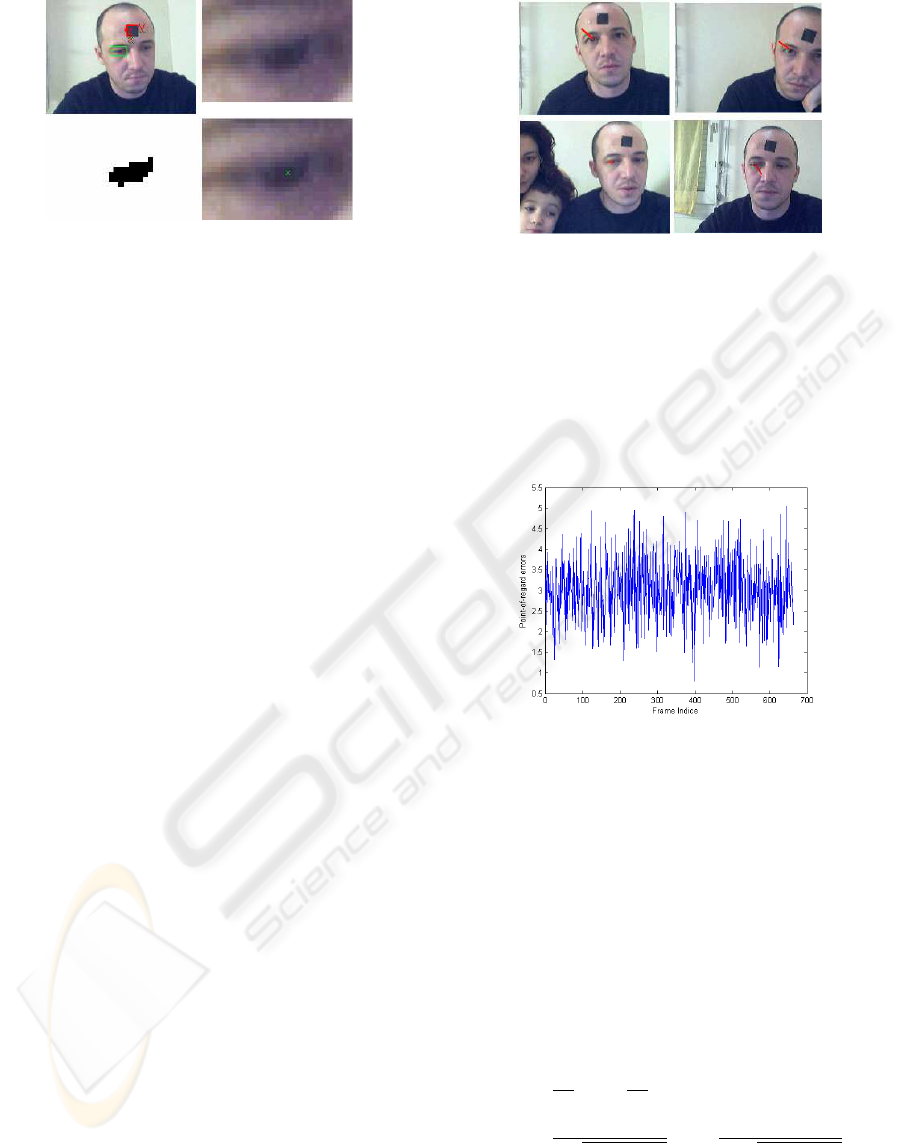
Figure 7: Pupil Tracking.
sation. In this example, hough transform is not able
to localise the iris.
3 EXPERIMENTAL RESULTS
In order to test the performance of our algorithm for
visual direction estimation in a real-time gaze track-
ing system, we have made some experiments using
several real face image sequences. Also, to investigate
the accuracy, we have made experiments in a known
environment.
There were four markers placed on the four cor-
ners on the screen. We take the 3D coordinates of
the four markers as the reference coordinates for the
true point-of-regard. The errors of the algorithm are
computed by comparing the estimated point-of-regard
and the reference coordinates. Video cameras were
placed at the top of the screen and input image size
was 320 × 240 pixels. The person sits 0.65m away
from the camera pair; in this configuration the user
has enough space for free movement. The horizontal
distance between markers was 29cm and the vertical
distance was 22.5cm (screen 14in). We ask the sub-
ject to stare at a marker on a desktop screen using his
gaze while moving the head (rotation, translation).
Figure 8 shows some images obtained in a real-time
gaze detection experiment. The 3D gaze vectors are
superimposed on the tracking result, the low-right im-
age represent a degenerated case. The whole process
including face tracking and gaze detection takes about
83 ms, thus the 3D point-of-regard can be determined
at 13Hz.
Errors of these algorithms performance on four dif-
ferent sequences are listed in figure 9, figure 10, fig-
ure 11, figure 12 corresponding respectively to mark-
ers 1 to 4. We can see the average error of point-of-
regard is less than 3cm for the Marker 1; this marker
is used in oculometric calibration process. The sec-
ond upper marker the average error of point-of-regard
is less than 4.2cm and the two lower markers the av-
erage errors are less than 5.9cm. However, we did
Figure 8: Eye gaze detection.
not take into account the degenerated cases (Marker1
≈ 14%, Marker2 ≈ 18%, Marker3 ≈ 23%, Marker4
≈ 21%,). Indeed, during the tracking process, our al-
gorithm sometimes loses the head or the pupil and in
those cases, we get outliers.
Figure 9: Point-of-regard error of the marker 1.
We also noticed that in our method as in other
analytical approaches, the accuracy of gaze tracking
greatly depends upon the resolution of the eye im-
ages. Suppose that the size of an eye image is 35×25,
which is a situation when the person is from 65 cm to
the screen, the range of the pupil movement is then
about 16 pixels. Let’s consider our method of cal-
culating the gaze direction (figure 13). In the figure,
|l| ∈ [0, 8] pixels, r ≈ 20 pixels. The smallest level
unit of l is |∆l| = 1 pixel. Then,
θ = arcsin l/r
∆θ ≈
∂θ
∂l
∆l +
∂θ
∂r
∆r (5)
=
1
r
q
1 − (l/r)
2
∆l −
1
r
2
q
1 − (l/r)
2
∆r
Supose ∆r = 0, then for |l| ∈ [0, 8] pixel, |∆θ| =
[2.86
◦
, 3.41
◦
]. Thus, the smallest unit of θ, i.e. the
resolution of gaze direction is about 3.2
◦
. If the iris
EYE AND GAZE TRACKING ALGORITHM FOR COLLABORATIVE LEARNING SYSTEM
331
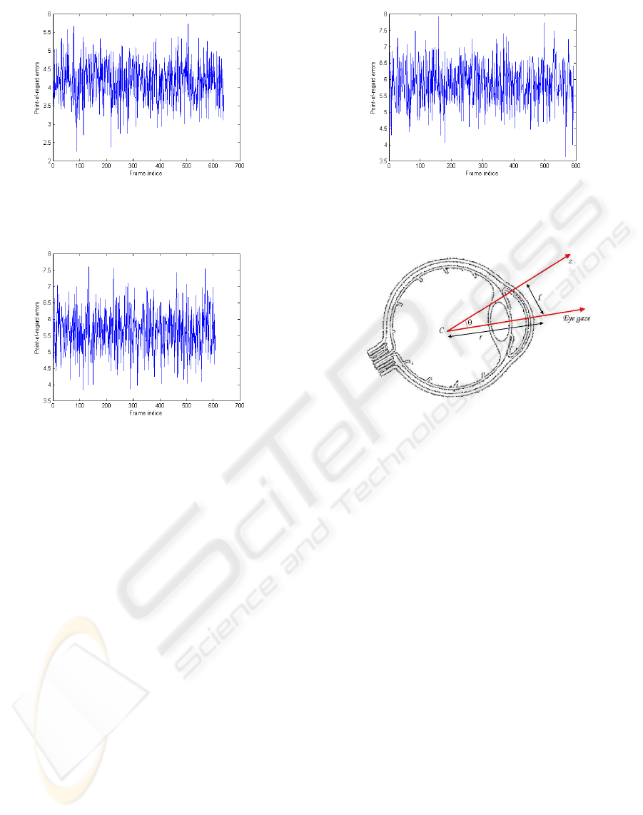
Figure 10: Point-of-regard error of the marker 2.
Figure 11: Point-of-regard error of the marker 3.
detection has a small error of 1 pixel, it will gener-
ate a tracking error of about 3.2
◦
of gaze direction.
Therefore, it is hard to determine the gaze in a 3D
scene accurately with such low resolution, neverthe-
less in our use we only need to determine a region in
the screen.
4 CONCLUSION
In this paper, a real-time implementation of a new
method to estimate gaze direction using stereo vision
is proposed. The motivation of our approach is to de-
velop a low-cost device allowing to estimate the eye
gaze robustly in real-time and with satisfactory ac-
curacy. The first originality of our algorithm is the
use of the target in order to recognize, localize and
finally to quickly track the head of all persons. Also
by using the described ”oculometric calibaration” de-
scribed, we were able to discard other features detec-
tion and obtain a proper eyeball center. Because of
this, our method is adapted to different person and the
accuracy of the visual direction should not be affected
by the change of head pose. In summary, we devel-
oped a low-coast system (only two webcams) which
Figure 12: Point-of-regard error of the marker 4.
Figure 13: Image resolution problem.
observes a person without giving him/her any discom-
fort and shortly, this system will be applied for the
collaborative tasks survey.
Currently, our algorithm is coded with Matlab and
we got a satisfactory execution speed (13Hz), in our
future work; we will increase processing speed of the
system by using C++. We also aim to improve the
accuracy by using high resolution camera and other
image processing tools to detect the pupil (not the iris
center).
REFERENCES
A.Corbel, P.Jaillon, Serpaggi, X., Baker, M., Quignard,
M., Lund, K., and Sjourn, A. (2003). A drew: Un
outil internet pour crer des situations d’apprentissage
cooprant. In Environnements Informatiques pour
l’Apprentissage Humain (EIAH 2003), Strasbourg,
France.
Anders, G. (2001). Pilots attention allocation during ap-
proach and landingeye- and head-tracking research in
an a330 full flight simulator. In International Sympo-
sium on Aviation Psychology (ISAP).
Baker, M., Lund, K., and Quignard, M. (2002). Multi-
representationnal argumentative interactions : the case
of computer-mediated communication in cooperative
ICINCO 2006 - ROBOTICS AND AUTOMATION
332

learning situation. In Proceedings of the Fifth Inter-
national Conference of the International Society for
the Study of Argumentation (ISSA’02), Sic Sat, Ams-
terdam.
Baluja, S. and Pomerleau, D. (1994). Non-intrusive gaze-
tracking using artificial neural networks. In Neural
Information Processing Systems, Morgan Kaufman
Publishers, New York.
Cho, Y. and Neumann, U. (1998). Multi-ring color fiducial
systems for scalable fiducial tracking augmented real-
ity. In Proceedings of the Virtual Reality Annual In-
ternational Symposium (VRAIS98), page 212, Wash-
ington, DC, USA.
Collewijn, H. (1999). Multi-representationnal argumenta-
tive interactions : the case of computer-mediated com-
munication in cooperative learning situation. In H. S.
Carpenter and J.G.Robson [Eds.], Vision Research:
A practical Guide to Laboratory Methods, pages 245–
285, Oxford: Oxford Univ. Press.
Duchowski, A. T. (2002). A breadth-first survey of eye
tracking applications. In Behavior Research Methods,
Instruments, and Computers.
Fiala, M. (2005). Artag, a fiducial marker system using digi-
tal techniques. In Proceedings of the 2005 IEEE Com-
puter Society Conference on Computer Vision and
Pattern Recognition (CVPR05), Volume 2, pages 590–
596, Washington, DC, USA.
Glenstrup, A. and Nielson, T. (1995). Eye controlled media
: Prensent and future state. In Masters thesis, Univer-
sity of Copenhagen.
Henderson, J. M. and Hollingworth, A. (1998). Eye
movements during scene viewing: An overview. In
G.Underwood (Ed.), Eye Guidance in Reading and
Scene Perception.
Kato, H. and Billinghurst, M. (1999). Marker tracking and
hmd calibration for a video-based augmented reality
conferencing system. In Proceedings of the 2nd IEEE
and ACM International Workshop on Augmented Re-
ality (IWAR99), pages 85–92, Washington, DC, USA.
Kato, H., Billinghurst, M., Poupyrev, I., Imamoto, K., and
Tachibana, K. (2000). Virtual object manipulation on
a table-top ar environment. In Proceedings of the In-
ternational Symposium on Augmented Reality (ISAR
2000), pages 111–119, Munich, Germany.
Kim, K. and Ramakrishna, R. (1999). Vision-based eye-
gaze tracking for human computer interface.. In Inter-
national Conference on Systems, Man, and Cybernet-
ics, pages 324–329.
Matsumoto, Y. and Zelinsky, A. (2000). An algorithm for
real-time stereo vision implmentation of head pose
and gaze direcetion measurement. In International
Conference on Automatic Face and Gesture Recogni-
tion, pages 499–504.
Naimark, L. and Foxlin, E. (2002). Circular data ma-
trix fiducial system and robust image processing for
a wearable vision-inertial self-tracker. In Proceedings
of the International Symposium on Mixed and Aug-
mented Reality (ISMAR02), pages 27–36, Washing-
ton, DC, USA.
Pastoor, S., Liu, J., and Renault, S. (1999). An experimen-
tal multimedia system allowing 3-d visualization and
eyecontrolled interaction without user-worn devices.
In IEEE Trans. Multimedia, 1(1), pages 41–52.
Perona, P. and Malik, J. (1990). Scale-space and edge de-
tection using anisotropic diffusion. In IEEE Transac-
tions on pattern and machine intelligence. Vol 12. NO.
7, pages 629–639.
Pomplun, M., Velichkovsky, B., and Ritter, H. (1994).
An artificial neural network for high precision eye
movement tracking. In B. Nebel and L. Drescher-
Fischer (Eds.), Lectures Notes in Artificial Interlli-
gence, Springer Verlag, Berlin.
Reingold, E. M., Charness, N., Pomplun, M., and Stampe,
D. M. (2002). Visual span in expert chess players:
Evidence from eye movements. In Psychological Sci-
ence.
Rekimoto, J. (1998). Matrix : A realtime object identifica-
tion and registration method for augmented reality. In
Proceedings of the Third Asian Pacific Computer and
Human Interaction (APCHI98), page 6368, Washing-
ton, DC, USA.
Rekimoto, J. and Ayatsuka, Y. (2000). Cybercode : de-
signing augmented reality environments with visual
tags. In Proceedings of DARE 2000 on Designing aug-
mented reality environments (DARE00), pages 1–10.
Sibert, L. E. and Jacob, R. J. (2000). Evaluation of eye gaze
interaction. In Human Factors in Computing Systems:
CHI 2000 Conference Proceedings. ACM Press.
Stiefelhagen, R. and Yang, J. (1997). Gaze tracking for mul-
timodal human-computer interaction. In International
Conference on Acoustics, Speech, and Signal Process-
ing, pages 2617–2620.
Toyama, K. (1998). Look, ma . no hands!. hands-free cursor
control with real-time 3d face tracking. In Workshop
on Perceptual User Interfaces.
Wang, J. G., Sung, E., and Venkateswarlu, R. (2003). A eye
gaze estimation from a single image of one eye. In
Proceedings of the Ninth IEEE International Confer-
ence on Computer Vision (ICCV 2003) 2-Volume.
Wu, H., Chen, Q., and Wada, T. (2005). Visual direction
estimation from a monocular image. In IEICE Trans.
Inf. and Syst., Vol. E88D, No.10., pages 2277–2285.
Zhang, Z. (1999). Flexible camera calibration by viewing
a plane from unknown orientations. In IEEE Interna-
tional Conference on Computer Vision.
Zhu, J. and Yang, J. (2002). Subpixel eye gaze tracking.
In IEEE International Conference on Automatic Face
and Gesture Recognition.
EYE AND GAZE TRACKING ALGORITHM FOR COLLABORATIVE LEARNING SYSTEM
333
