
STATIC FACE DETECTION AND EMOTION RECOGNITION WITH
FPGA SUPPORT
Paul Santi-Jones and Dongbing Gu
University of Essex
Wivenhoe Park, Colchester, Essex, CO4 3SQ, UK
Keywords:
FPGA, Neural Network, emotion recognition, face detection, skin colouring, sized skin detection, embedded
processor support, Fractional Fixed Point, integer neural networks, HSL.
Abstract:
Throughout history, spoken language and face-to-face communication have been the primary mechanics of
interaction between two or more people. While processing speech, it is often advantageous to determine the
emotion of the speaker in order to better understand the context of the meaning. This paper looks at our
current effort at creating a static based emotion detection system, using previously used techniques along with
a custom FPGA neural network to speed up recognition rates.
1 INTRODUCTION
Our research focuses on developing a fast and effi-
cient method of facial emotion recognition for use
within a humanoid robot for a museum environment
using embedded systems. As interactivity is key to the
robotic application, speech is the primary control sys-
tem. Orders and questions are issued via natural lan-
guage, as well as an onboard touch screen. As there
is the possibility that the speech recognition software
cannot determine what the user has requested, given
a default noisy environment, facial emotion recogni-
tion is also to be utilised. The robot features a built-in
computer system, but is not computationally power-
ful enough to process all forms of data entered into
the system at a satisfactory rate. In order to combat
against the lack of power, embedded systems, along
with Field Programmable Gate Arrays (FPGAs) have
been investigated into how to speed up the process.
Our aims are to create a new neural network system
for the FPGA which can process all the visual in-
formation sent to the device. As there are limited
data transfer rates between the FPGA and the cameras
mounted in the head of the robot, the amount of data
to be sent needs to be reduced in an efficient and quick
processing system executed on the computer before-
hand. Our main contribution of this paper is to give
knowledge of the new FPGA network, with an exam-
ple of application as the bulk of the content.
There has already been a significant amount of
work conducted into emotion recognition (Fasel and
Luettin, 2003) in terms of both psychology and com-
puter implementations. Research is generally split
into two different methods, one using motion data to
help determine the difference in emotion (dynamic),
the second using single frame images (static).
A great deal of this research has focused on the dy-
namic method, due to its relative ease of program-
ming and simplicity (Bassili, 1979). Sequences of
images are taken and recorded so that the motion of
the changes in facial patterns can be seen over a fi-
nite time length. It is then possible to use these facial
changes to determine which muscles have moved in
the face using motion vectors and statistic routines,
such as graph analysing (I. Essa, 1994; N. Kruger,
1997), Hidden Markov Models (Cohen et al., 2000)
or Bayesian networks (Cohen et al., 2003).
However, the following disadvantages of dynamic
systems were raised in our decision on which method-
ology to utilise:
1. The face has to be a stationary profile image. The
methods already devised in dynamic systems ex-
pect that particular parts of the face will move in
certain locations. If the face is not front wise show-
ing, the expected movements will not collaborate
with the motions stored in the database, resulting
in erroneous results. Also, if the face moves to one
side during the sequence of images, rather than the
algorithms detecting the action as a change in fa-
cial position, it will most likely be interrupted as a
390
Santi-Jones P. and Gu D. (2006).
STATIC FACE DETECTION AND EMOTION RECOGNITION WITH FPGA SUPPORT.
In Proceedings of the Third International Conference on Informatics in Control, Automation and Robotics, pages 390-397
DOI: 10.5220/0001205903900397
Copyright
c
SciTePress

facial feature movement instead. It is most likely
the subjects being studied will move at some stage
in the applied museum environment.
2. Having more than one face on screen can also cause
a problem. As the dynamic systems are designed
towards single motion vectors, multiple vectors on
screen at once could cause an erroneous result, al-
though it would be possible to make some changes
to the programming code to alleviate these poten-
tial errors. In the museum environment, it would be
most likely that people gather in crowds to see the
robot in operation.
3. In a real world environment, you can not guarantee
a specific constant frame rate. The result depends
on the sensitivity of the algorithm in question, but
are most likely to be affected in some way. Also,
noise from the image may be interpreted as move-
ment in a dark location.
4. Another problem with dynamic systems is the use
of relative positions. Normally, if the subject has
a neutral facial expression, and then moves onto
another emotion using the sequence, the database
of movements can detect these changes and deter-
mine the new emotion correctly. If the sequence of
images starts mid-emotion however, the database
would most likely fail to find the appropriate emo-
tional result.
5. Although the motion movement algorithm is fairly
simple and quick to run, complex post-processing
algorithms are needed to match those up with facial
expressions stored in a database.
Due to the aforementioned issues, our research
focuses on the static approach to emotion recogni-
tion, taking and analysing one image at a time. The
problem of pattern matching can be solved with pre-
existing techniques such as neural networks, tem-
plate matching, statistical methods and also sequen-
tial processing. Each of these methods require a
small amount of time to process a single iteration of
the algorithm used, but given the amount of data ap-
plicable to image processing tasks, runs into seconds.
Neural networks and template matching require rela-
tively small amounts of code to execute a single itera-
tion, which makes their use in embedded systems de-
sirable. For static based systems, which are of similar
area to the face finding application, neural networks
make up the majority of the architecture used (Sung
and Poggio, 1998; Rowley et al., 1998; Schneider-
man, 2000).
1.1 Summary
Static facial emotion detection is a related problem
of face finding in an image, which neural networks
are generally applied to. Most methods rely on find-
ing the whole face, while others are part based, try-
ing to locate individual elements. For both practical
and academic purposes, our application of the FPGA
neural network focuses on using a single-image parts
based system, which has seen relatively less attention.
Several new techniques for reducing the search area
will be introduced. The Facial Action Coding Sys-
tem (FACS) database (Ekman, 1978) will be used as a
base reference, and also for determining which Action
Units (AUs) of facial muscles make up an emotion.
2 METHODOLOGY
Our studies into FACS reveal there are three main ar-
eas of the face that are responsible for determination
of emotion, which are the eye and eyebrow, nose and
expression line, and the mouth, each of which slightly
overlaps the other. Three neural networks are em-
ployed for recognition of each area, which in turn out-
put several AUs classifiers. As each neuron can result
in a combination of several different AUs, a fourth
network is used for overall emotion recognition, us-
ing the outputs of each previous neuron as input.
While pattern recognition methods such as neural
networks and template matching can be trained to
recognise parts of the face using pixel data, it is of-
ten advantageous to use some sort of a feature extrac-
tion method. Not only can feature extraction give in-
formation which cannot be learnt with normal pixel
data, but non-pixel data also helps to solve the prob-
lem of illumination in different photo images (Viola
and Jones, 2002). However, both template matching
and neural networks methods are fairly slow, espe-
cially when executed several thousand times for each
pixel on the image.
In order to accelerate recognition speeds, a series
of existing algorithms are used in conjunction with
modified and new ideas, to be utilised in addition with
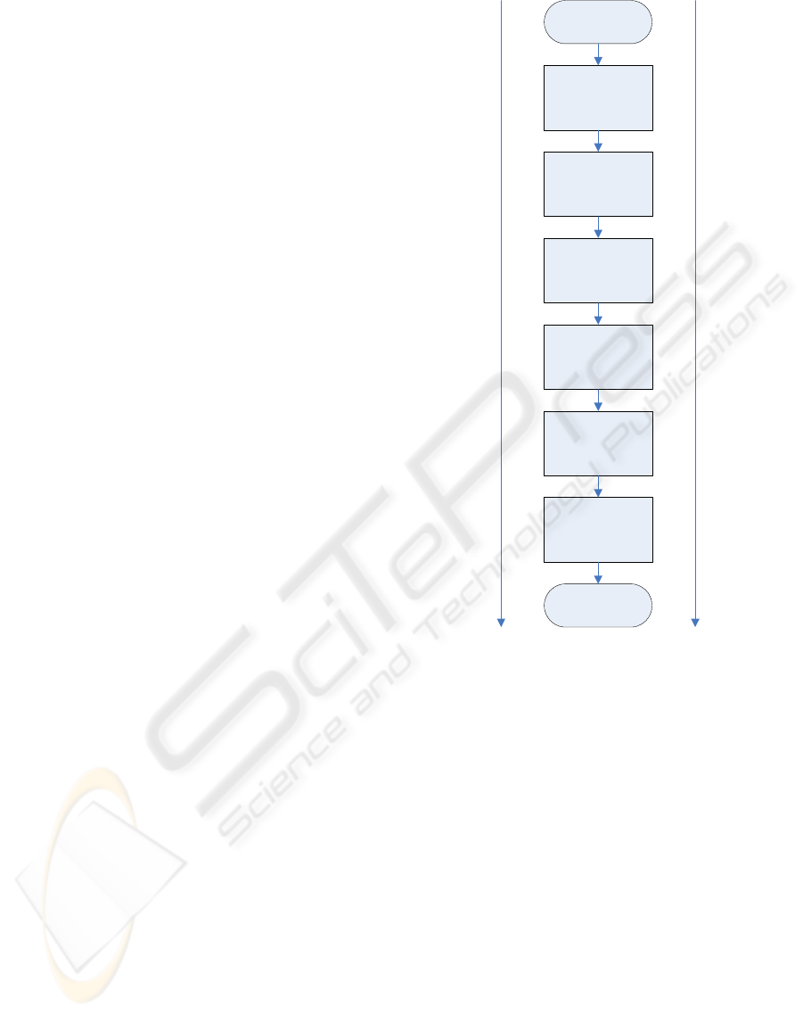
our neural network FPGA routines. Figure 1 shows
the architecture of the system, which features simple
processing (with the most data) at the start, with more
complex processing at each incremental state, con-
sisting of less data to finish. The algorithm includes
aspects of Hue Saturation Luminance (HSL) colour
conversion, skin detection, neural networks, and the
theory of linear perspective.
In addition to these methods, it is also possible to
take the theory of proxemics into account. Proxemics
is a psychological study into human interaction and
association with space. It has been shown in numer-
ous experiments that people, depending on the context
of their conversation, stand a certain distance apart
from each other whilst talking. The distance involved
depends on the type of conversation, how well the
STATIC FACE DETECTION AND EMOTION RECOGNITION WITH FPGA SUPPORT
391
two people know each other, and whether or not the
people involved are either being aggressive or defen-
sive against each other. There are four brackets of
distance; intimate, personal, social and public. Each
category of distance has been associated with an esti-
mated range of values where the brackets lie, with two
subgroups labelled close and far. For humanoid ro-
botics, the “close-personal” value can be used, which
lies around the 45-75cm range (Hall, 1990). There-
fore, the study of proxemics can be used to reduce the
search space, which will be shown in a later section.
2.1 Assumptions
Assuming the person wishing to order or question the
robot via speech is facing the camera, proxemics dic-
tates they will be most likely be in the range of 45-
75cm. In addition to this, the search space on the
image can also be reduced by another human psychol-
ogy aspect where people usually face each other when
communicating. Essentially, this means we can as-
sume there will be a face in the middle of the camera
image when speech communication is initialised.
The robot has access to a series of sonar and laser
detectors mounted around itself at leg height. Be-
ing the average human height of 170cm, the robotic
controller can therefore detect someone approaching,
and activate the face recognition routines when neces-
sary. Due to restrictions from the museum that com-
missioned the robot, movement is limited to within a
range of a reference point, and so cannot move around
freely; for the moment at least.
2.2 Sized Area Skin Detection
As there is only a limited amount of transfer band-
width between the cameras and the FPGA network,
the amount of data to send must be reduced, but must
be done using a method which uses little computa-
tional power on the computer system. The Sized Area
Skin Detection algorithm has been designed for this
particular application in mind, by using a simple iter-
ative process with skin colour detection.
The skin detection algorithm employed converts
the currently inspected Red Green Blue (RGB) pixel
value into Hue Saturation Luminance (HSL), which
is then passed to the skin colour formula. HSL is
another form of colour space, which has been cred-
ited with eliminating some of the problems associated
with classification of different colours. Visualisation
of the HSL space is normally shown as a cone shape,
but is more practical to shape its true representation
as a tube, as depicted in Figure 2. The Hue element,
which rings around each slice in the tube, gives the
uniqueness of colour; red is shown at 0
O
, green at
120
O
, and blue at 240
O
. Saturation determines how
HSL Conversion
Sized Skin
Detection
Algorithm
Template
Matching on Areas
Found
Neural Network
Distance/
Orientiation
Estimation
Emotion
Recognition using
Neural Network
START
FINISH
Complexity
Increasing
Data Amount
Decreasing
Figure 1: Methodology and Overview of Research Project.
intensive the colour is; the middle of the tube gives a
grey colour, while the outside of the tube is the full
colour as represented by the Hue element. Finally,
the Luminance value represents the luminosity of the
slice that is currently being used. Conversion from
RGB to HSL is a fairly straight forward process, with
a number of different implementations available on
the Internet. One of the advantages of using HSL is
that it makes the application of skin colour detection
a more feasible task as ranges of colour are easier to
inspect. At any stage during the process, it is possi-
ble for the algorithms to re-estimate the skin colour
formulae with the new current data that the image is
looking at.
Rather than inspecting every pixel within the im-
age, the algorithm looks instead at varying sized gaps
of pixels, trying to focus on the areas which are most
likely to contain a face for further processing. To be-
gin with, every xth pixel on both the horizontal and
vertical plane are inspected to determine if there is
ICINCO 2006 - ROBOTICS AND AUTOMATION
392
Luminance
Saturation
Hue
Figure 2: Hue Saturation Luminance Colour Space.
a skin colour match, and the results stored in a data
structure. Using this information, the algorithm can
then attempt to locate general areas of interest by then
reducing the skip space.
When the specific skip size iteration has completed
on the selected image, the created data structure is
inspected by a second-stage algorithm. The routine
looks at each pixel in the structure which was labelled
as matching skin colour, and tries to focus successive
searches of the image by determining which skip ar-
eas have matches. After doing so, it is therefore possi-
ble to inspect the middle of a skip size (
x
2
) by reducing
the skip value for a designated line on the image.
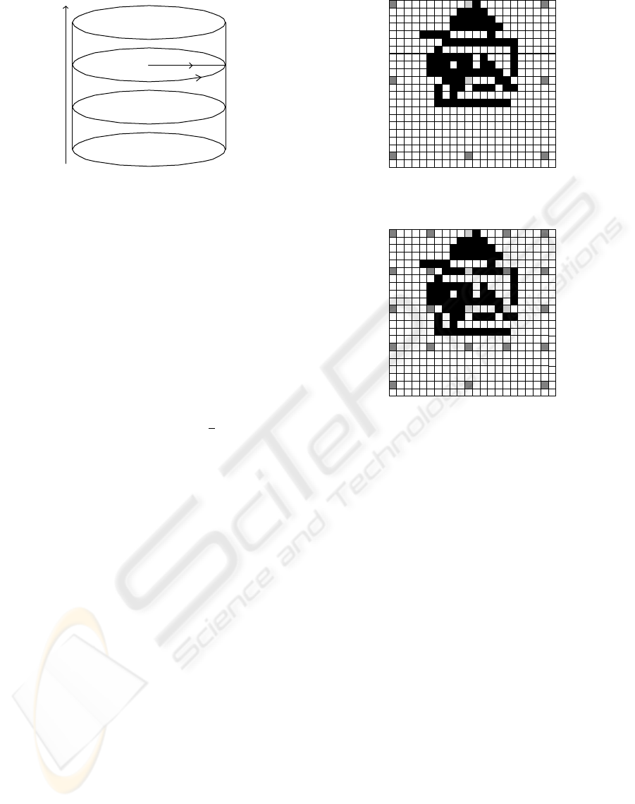
Figure 3 shows the first stage of an example
process, where the skip size is set to ten. Each block
represents a pixel. Black blocks represent skin colour
pixels, dark grey blocks represent pixels that were in-
spected, but were not skin colour, and light grey boxes
show inspected pixels that were a match. Figure 4
shows the next iteration of the algorithm.
As there was a difference between the first and sec-
ond inspected pixel on the first line, the step size was
reduced to search in-between them, which has been
determined to not be a match. On the same line again,
as the second and third pixels also differed, the skip
size is reduced to again focus the algorithm on other
points on the image. As well as working horizontally,
the same methodology is applied vertically. Eventu-
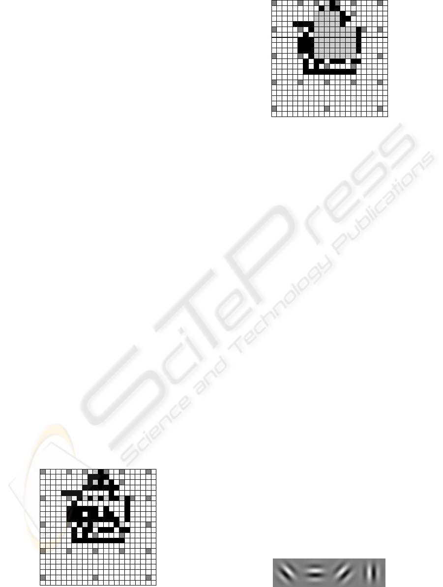
ally, continuing this method, Figure 5 is produced.
The algorithm can be repeated as many times as nec-
essary, to reduce the search space further, although
there is a trade-off between speed and the percentage
of the number of face pixels inspected. If an inade-
quate amount of iterations are used, there is a chance
that part of the optimal solution will not be found,
as shown in the last figure. As the data is measured
in pixels here though, it is unlikely that there will be
any major side effects to using this algorithm. Once
the desired number of iterations have been completed,
the algorithm should assume that any pixels within
the “found” areas are also points of interest, as can be
Figure 3: HSL Sized Skin Detection - Step 1.
Figure 4: HSL Sized Skin Detection - Step 2.
shown in Figure 6.
Only large segments of skin colour will be de-
tected using this algorithm (which are most likely to
be the face), with smaller irrelevant individual pixels
removed. It should be noted that after a few iterations,
most of the area has been detected, and that possible
further iterations would result in the rest of the data
being located.
Tests conducted show that two or three iterations
with a spacing of twenty is sufficient to find most of
the facial area on a 384 by 288 pixel image, which can
typically find 80% or higher of the total skin area.
2.3 Feature Extraction & Template
Matching
Once the most likely areas of interest have been
detected, the more computationally expensive algo-
rithms of feature extraction and template matching
can begin. As mentioned previously, using feature ex-
traction as a precursor to neural networks allows the
neurons to execute and train on data that might be ex-
tremely difficult or impossible to learn. In this line of
research, four biologically inspired Gabor wavelet fil-
ters (see Figure 7) have been used to find the feature
data, being horizontal, vertical, diagonal up and diag-
STATIC FACE DETECTION AND EMOTION RECOGNITION WITH FPGA SUPPORT
393
onal down at size 11x11. Once the Gabor filter has
been applied to the individual pixel being inspected,
the four outputs are stored within another data struc-
ture. The template itself is an eye, as the eye is the
most prominent feature on the human face (Rowley
et al., 1998), and also gives the most striking differ-
ences of feature data on the whole of the face. Once
enough data has been collected, template matching
can be executed, which is based on a least-squared
error checking. There may be several points on the
image which give the least error using the template
after execution on the area of interest. The template is
trained with an average of several eye samples, but
should still remain rather general. The two points
with the least error are most likely to be the eyes, al-
though some additional checking can be used, which
is described in the next section.
2.4 Distance Estimation
“Linear perspective” is the scientific application of
distant objects appearing smaller than closer ones of
the same size. While stereopsis is the main area of re-
search for object distance estimation, linear perspec-
tive has seen little attention. Earlier work on the sub-
ject has proved that linear perspective can be used in a
visual system as a very fast method of estimating the
distance of a marker used within a 3D motion captur-
ing system, using only one camera (Jones, 2003).
It is possible to determine the distance of an ob-
ject, from the camera, if two points on both the ac-
tual physical entity and on the resultant captured im-
age are known. The physical and image distances can
be calibrated together by taking various image of the
real object at specific distances from the camera, and
recording the image distance between the two points.
Once the data has been collected, it is then possible
to apply these values to an equation generating algo-
rithm, such as the use of the Casio fx850 graphical
calculator, which can produce a cubic equation to cor-
relate physical distance given camera distance.
Figure 5: HSL Sized Skin Detection - Step 3.
Figure 6: HSL Sized Skin Detection - Step 4.
This equation can be used to determine the esti-
mated distance of the two points from the camera,
given the distance in pixels of the same two points
which appear on screen. In addition to this applica-
tion, it is also possible to be used in conjunction with
distance estimation of a human face from the camera.
The two eyes of the subject are a fixed value, on aver-
age, being 64mm apart from each central point of the
eye to the other (Wikipedia, 2006).
Using such information can be beneficial in two
different ways. Firstly, it can act as a check to de-
termine if two or more eye templates are realistically
related to each other. If the distance estimation al-
gorithm determined that two templates were too far
away, too close, or not in the proxemic range to ac-
tually be seen on screen when they actually are, it is
most likely that either one of them is an erroneous
template match, and can be discarded. Secondly, us-
ing distance estimation between two eyes can help in
the process of determining other feature locations of
the face, such as the ears, forehead, nose and mouth.
Figure 8 shows the link between eyes, nose and
mouth. If the position of the eyes is known, from
template matching, the location of the nose and mouth
can be located using a combination of linear perspec-
tive and trigonometry. The nose and mouth trajec-
tory lies perpendicular to the central point between
the eyes. The length between the mouth and the cen-
tral part in between the eyes is approximately 70mm.
For example, if the eyes are 100 pixels across on an
image, that 100 pixels represents a distance of 64mm
in the real world. Equation 1 can be used to deter-
mine the offset of the mouth, where n is the number
of pixels between eyes.
Figure 7: Gabor Feature Templates.
ICINCO 2006 - ROBOTICS AND AUTOMATION
394
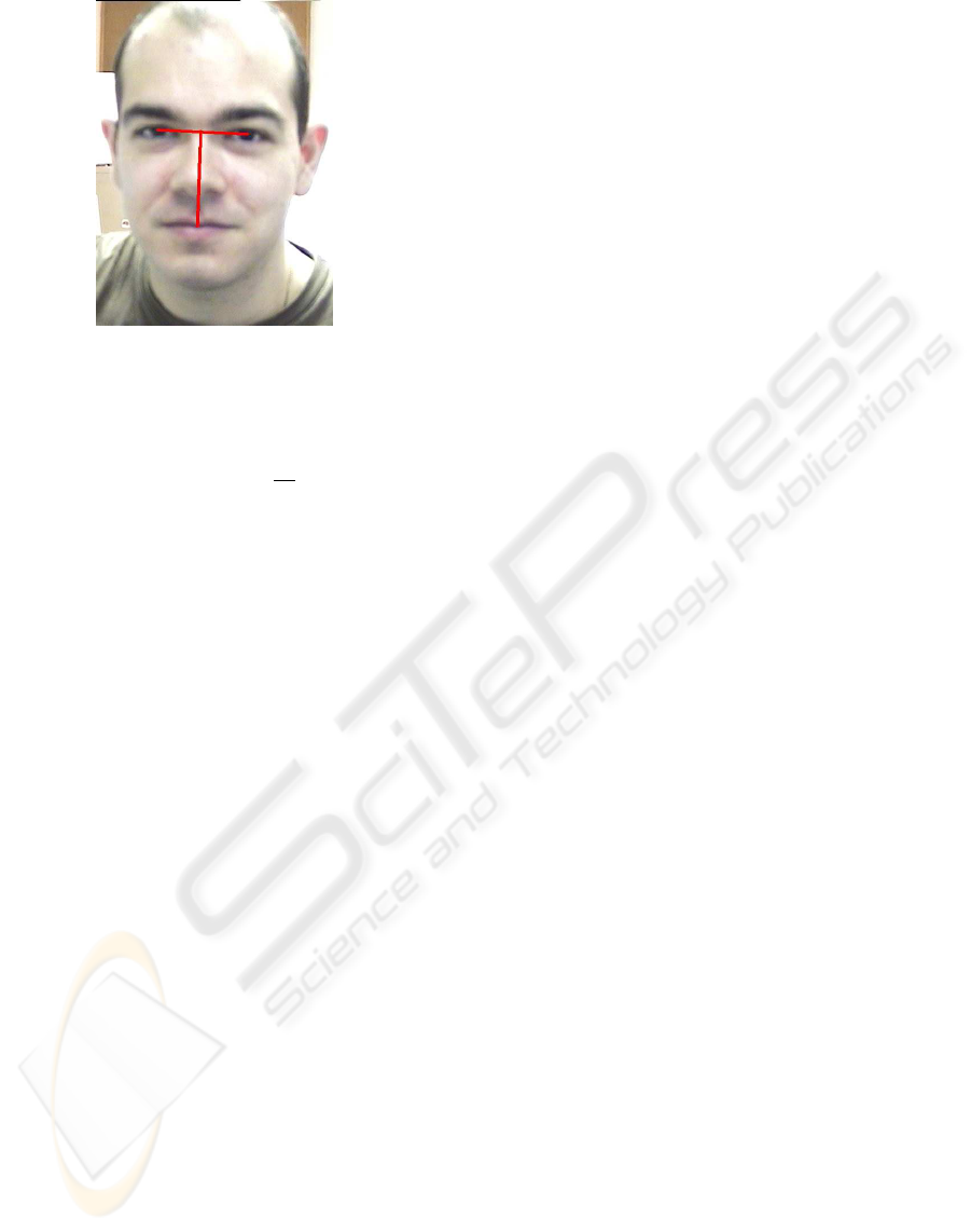
Figure 8: Link Between Eyes, Nose, Mouth.
mouth distance(n) =
n
64
× 70 (1)
While it is certainly not necessary to use a cubic
equation to estimate the other parts of the face, where
a simple linear equation would work just as well, the
depth information the cubic formula gives can also be
used for the robotic controllers. Estimating the dis-
tance can be used in such operations as hand shaking
with the person, and also allowing the robot to have
its own “personal space” with which it does not want
violated, emulating a person. The personal space of
the robot is also a way of making sure the face which
is being tracked for detection and emotional recogni-
tion is within the certain threshold of the proxemics
mark, and therefore within search range.
2.5 Feature Finding
Using the techniques above, it is possible to reduce
the final interest area to a few hundred pixels or so.
The more complex neural networks can now be em-
ployed, which try to determine the combination of
AUs that are being shown from each of the three sec-
tions of the face that the system investigates. Each of
these networks are executed for each pixel of inter-
est, within the estimated location of where the facial
feature should be, and each one outputs a classifica-
tion value and several AUs. The classification value is
used to determine if the data entered into the network
correctly matches the object it has been trained for,
and can also be used to determine how much atten-
tion should be paid to the final overall emotion recog-
nition result. Generally the areas where the classifica-
tion results are highest will be the actual location of
the features being searched for, and the AU outputs
of those points should be recorded for the next stage.
Each network is trained using several different AUs
from the same section of the face, and sized down in
order to fit the number of inputs.
Once the computer has found the most likely area
of the face, the pixel information is encoded into an
integer based system, which is then transferred to the
FPGA neural network. As mentioned previously, our
research is focused on developing this network struc-
ture for common use, with the application of emo-
tion recognition as an example of usage. We have de-
veloped a new neural network structure, named Frac-
tional Fixed Point (FFP) which uses neurons based
on fractional mathematics, rather than regular float-
ing point calculations. Although floating point is eas-
ily implemented on the FPGA in Handle-C, it requires
a large amount of gates, therefore making large scale
networks unfeasible on small-medium size capacity
chips.
Our new network is based on integer mathemat-
ics, making a lot more efficient system, which can be
scaled up considerably. We are still investigating if
this new system can be used for general purpose ap-
plications, and its ability to train on a large range of
input data such as pixel information. Training is con-
ducted on a computer using a Genetic Algorithm and
an FPP simulator. Once there is a sufficiently small
error, the weights are then copied over to the FPGA
system (Santi-Jones and Gu, 2006).
Currently, our FFP neural network consists of 775
inputs, which is an input matrix of 31 by 25 pixels.
The structure of the system uses a tiered layer archi-
tecture in the form of a pyramid. Each 4x4 square
group of pixels is connected to the neuron in the sec-
ond layer, and a 4x4 group into the third layer un-
til the output neurons are reached. Figure 9 shows
a front wise illustration of the neural structure used
on a small scale network. Dark squares indicate
first layer neurons, while lighter ones indicate second
layer ones. Please note that the third layer neurons
would combine a 2x2 input matrix using the second
layer neurons, resulting in a single neuron for the third
layer in this illustration. Figure 10 shows a sideways
view of network, with the left most squares indicating
first layer neurons, and right most the third layer. This
configuration occupies an estimated 200,000 gates in
the current version of our software, but is likely to
change with future revisions due to extra functional-
ity or code optimisation. A single execution of the
network takes around 800ns.
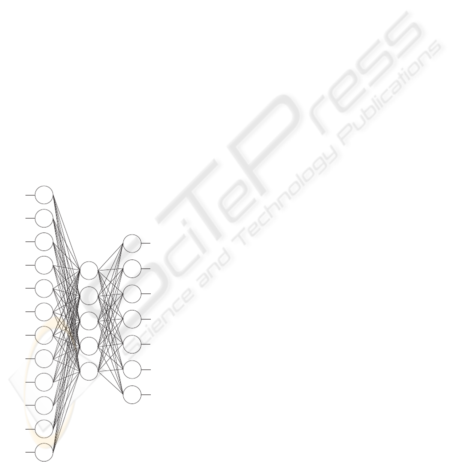
2.6 Emotion Recognition
Once each network has determined the facial features,
and the appropriate AUs of each feature, the emotion
classification network can be executed, which is de-
picted in Figure 11. Its twelve inputs consist of all the
AU outputs of the three previous networks, minus the
classification results, with five neurons in the middle
STATIC FACE DETECTION AND EMOTION RECOGNITION WITH FPGA SUPPORT
395
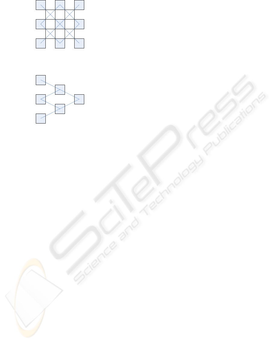
Figure 9: Front View of the network structure used.
Figure 10: Sideways view of the network structure used.
layer, and seven outputs, one for each of the univer-
sal emotions plus a neutral stance. After the network
has executed, the classification output values of the
previous networks can then be used to determine how
realistic the output of this final network actually is.
3 RESULTS
For the purposes of our experiments, we did not find a
suitable selection of input images on which to test the
system, based on our assumption for the robotic con-
troller. It was therefore necessary for us to capture
our own images. In order to reflect the true emotions,
rather than faked “on-cue” ones, we created a stand-
ing model of our robot and asked several volunteers to
interact with it. The robot itself was remote controlled
from another location, with access to the speech con-
trol systems, data information from the camera, and
an output stream coming from the microphone. It was
therefore possible for the “robot” to have a conversa-
tion with a human, making the person achieve each of
the six universal emotions in several circumstances.
Once the conversation had finished, and the subject
exited the room, a board of three members of dif-
ferent nationalities (English, Chinese, Greek) would
look at the image data from each capture, and deter-
mine whether they believed the expression on the per-
sons faces matched what they believed to be a certain
emotion. As the six emotions they were concentrating
on were universal, there was generally a consensus
among the members.
A total of ten subjects had three different circum-
stances for each of the six emotions recorded, which
was used in both training and also testing of the de-
tection system. Recognition rates of the emotion im-
age and the correct classification was around the 70%
mark. However, this failure of correct classification
was usually the result of one of the filtering processes
failing to identify the correct position/skin colour. In
terms of a visual emotion recognition system there-
fore, the system fails. However, as the application of
filtering is merely an application of the FFP neural
network system, other methods could also be used,
but is generally beyond the scope of our research.
4 CONCLUSIONS
Whilst most of our research into the FFP network is
still being refined, this paper offers some overlooked
aspects into the static facial emotion recognition field,
as well as demonstrating the use of the network in
question. Whilst the network itself is designed to be
general, the applied software models described in this
paper can be changed at will. While the static method
may be processor and pattern recognition intensive,
this paper has demonstrated several ways in order to
speed up the process, and also a method to estimate
the distance of the face, which has been ultimately
designed towards implementation in embedded sys-
tems.
REFERENCES
Bassili (1979). Emotion recognition: The role of facial
movement and the relative importance of upper and
lower areas of the face. Journal of Personality and
Social Psychology, 37:20492059.
Cohen, I., Garg, A., and Huang, T. (2000). Emotion recog-
nition from facial expressions using multilevel hmm.
Cohen, I., Sebe, N., Cozman, F. G., and Huang, T. S. (2003).
Semi-supervised learning for facial expression recog-
nition. In MIR ’03: Proceedings of the 5th ACM
SIGMM international workshop on Multimedia infor-
mation retrieval, pages 17–22, New York, NY, USA.
ACM Press.
Ekman, Friesen, H. (1978). Facial Action Coding System
(FACS). W.V. Consulting Psychologists Press, Palo
Alto, CA, USA.
Fasel, B. and Luettin, J. (2003). Automatic facial expression
analysis: A survey.
Hall, E. (1990). The Hidden Dimension. Bantam Doubleday
Dell Publishing Group. ISBN: 0385084765.
I. Essa, A. P. (1994). A vision system for observing and
extracting facial action parameters. In Proceedings
of IEEE CVPR 1994 Conference, pages 76–83, Seat-
tle,Washington.
ICINCO 2006 - ROBOTICS AND AUTOMATION
396
Jones, P. (2003). A low-cost motion capturing and display
system for home-based rehabilitation. Master’s the-
sis, University of Essex. Available at http://www.paul-
santijones.net.
N. Kruger, M. Potzsch, C. v. M. (1997). Determination of
face position and pose with a learned representation
based on labelled graphs. Image and Vision Comput-
ing, 15(8):665–673.
Rowley, H., Baluja, S., and Kanade, T. (1998). Rotation
invariant neural network-based face detection.
Santi-Jones, P. and Gu, D. (2006). Fractional floating point
neural networks: An alternative neural network sys-
tem for embedded systems. Still awaiting publication.
Available at http://www.paul-santijones.net.
Schneiderman, H. (2000). A statistical approach to 3d ob-
ject detection applied to faces and cars.
Sung, K. K. and Poggio, T. (1998). Example-based learning
for view-based human face detection. IEEE Transac-
tions on Pattern Analysis and Machine Intelligence,
20(1):39–51.
Viola, P. and Jones, M. (2002). Robust real-time object de-
tection. International Journal of Computer Vision - to
appear.
Wikipedia (2006). Wikipedia entry. http://en.wikipedia.org/
wiki/IMAX.
Brow
Lower
Inner Brow
Raiser
Outer Brow
Raiser
Upper Lid
Raiser
Cheek
and Lid
Nose
Wrinkler
Upper Lid
Raiser
Chin
Raiser
Lip
Corner
Depressor
Lips
Part
Jaw
Part
Lower Lip
Depressor
Neutral
Happy
Sad
Fear
Surprise
Disgust
Anger
Figure 11: Overall Emotion Recognition Network.
STATIC FACE DETECTION AND EMOTION RECOGNITION WITH FPGA SUPPORT
397
