
THE VISIBILITY PROBLEM IN VISUAL SERVOING
C. P
´
erez, R. Morales, N. Garc
´
ıa-Aracil, J. M. Azor
´
ın and J. M. Sabater
Virtual Reality and Robotics Lab. Universidad Miguel Hern
´
andez.
Avd. de la Universidad s/n. Edif. Torreblanca. 03202 Elche, Spain
Keywords:
Visual servoing, control, visibility, computer vision.
Abstract:
This paper deals with the visibility problems occurring during the execution of a visual servoing task. First,
a review of the scientific works related with the visibility are recalled and then the solution proposed by the
authors is presented and extended to the case of the sudden disappearance of features on the center of the
image. Experimental results demonstrate the improvements (stability and continuity) that can be obtained in
the performance of the vision-based control task when the weighted features formulation is used.
1 THE VISIBILITY PROBLEM
1.1 Related Work
Traditionally, the visibility problem/constraint has
been defined as: a minimum number of image fea-
tures must remain in the camera field of view during
the control task. In this section, the different solu-
tions proposed to solve the visibility problem in 2D
visual servoing tasks are revised. Many implementa-
tions in the literature use the potential fields to keep
all feature points inside the viewable portion of the
image plane at all times, as the partitioning method
(Corke and Hutchinson, 2001) and the path-planning
one (Mezouar and Chaumette, 2003).
In Mezouar and Chaummette(Mezouar and
Chaumette, 2003), a path planning scheme based
on the potential field method is presented. This
method allow to introduce constraints in the desired
trajectory to be realized. Such constraints are, for
instance, to ensure that the object of interest remains
in the camera field of view and to avoid the robot
joints limits. In counterpart, the analytical forms
of the trajectories in the image space are no longer
available, and the corresponding camera trajectory
deviates from the optimal one when repulsive forces
are involved.
In Corke and Hutchinson (Corke and Hutchinson,
2001), a solution to the problem of camera retreat
in 2D visual servoing approaches is presented. It is
based on decoupling the z-axis translation and rota-
tion from the image Jacobian and then controlling
them using simple image features (area, orientation of
a image vector). In this paper, the visibility problem is
considered as a collision avoidance problem and em-
ployed potential field techniques to repel the feature
points from the image boundary.
Gans and Hutchinson (Gans and Hutchinson, 2003)
have proposed another approach, namely switch-
ing between 2D and 3D visual servoing approaches.
Thus, whenever the visibility problem of 3D approach
is imminent, the control is switched to 2D one. If
camera retreat occurs, the control is again switched to
3D approach. In Chesi et al.(Chesi et al., 2002), an-
other switching strategy between several elementary
camera movements is proposed.
For a 6 dof visual servoing system, Malis et. al.
(Malis and Chaumette, 2002) guarantee that a single
feature point remains within the field of view while
guaranteeing convergence for a large basin of attrac-
tion. Morel et. al.(Morel et al., 1999) extend this idea
by decoupling the image-plane motion of a cleverly
chosen feature vector a circle containing all the fea-
ture points from the rotational motion of the camera;
by keeping this conservative feature vector within the
image plane, one is guaranteed that all feature points
remain within the camera field of view(though self-
occlusion avoidance is not guaranteed).
In Zhang and Ostrowski(Zhang and Ostrowski,
2002), optimal control techniques are employed for
design of image motion compatible with joint limits
and ensuring visibility, the cost function represent-
ing a time integral of energy. Similarly, Cowan et al.
(Cowan et al., 2002) uses navigation function, repre-
senting specially potential field functions with a min-
imum to be unique by construction.
Another recent solution to this issue is related to the
new intrinsic-free visual servoing approach (Malis,
2004). With this approach, it’s possible to imple-
482
Pérez C., Morales R., García-Aracil N., M. Azorín J. and M. Sabater J. (2006).
THE VISIBILITY PROBLEM IN VISUAL SERVOING.
In Proceedings of the Third International Conference on Informatics in Control, Automation and Robotics, pages 482-485
DOI: 10.5220/0001205104820485
Copyright
c
SciTePress
ment a simple focal length control strategy that allows
to keep the target in the field of view of the camera
during the servoing and recovers at the convergence
the focal length value of the reference image without
having any previous information about it (Benhimane
and Malis, 2003). In Schramm and Morel(F.Schramm
and G.Morel, 2004), the approach proposed uses the
movement of the camera backwards along its optical
axis to keep all points in the camera field of view dur-
ing the task execution.
1.2 Changes of Visibility in Image
Features
Contrary to the scientific works presented before, we
proposed the concept of allowing temporary disap-
pearance of image features(only through the image
boundary) during the execution of a vision-based con-
trol task (Garcia-Aracil and Malis, 2004). In this pa-
per, this concept is extended to the disappearance of
features in all the image space.
In (Garcia-Aracil and Malis, 2004), we described
the continuity problems of the control law due to the
changes of visibility in image features during a vi-
sual servoing task and also a solution to this problem
when features appear/disappear through the border of
the image was proposed. This solution is based on
weighting image features depending on the position
of them in the image plane Φ
uv
. The weights are used
in order to anticipate in some way the possible discon-
tinuities produced in the control law by the temporary
disappearance of image features through the border
(Figure 1, features number 1 and 4).
Imagesacquiredbythecameraindifferentsampletimes
ImageT
0
ImageT
K
ImageT
K+N
1
2
3
4
5
6
7
8
1
2
3
4
5
6
7
8
1
2
3
4
5
6
7
8
Object
Object
Object
Figure 1: The temporary disappearance concept in vision-
based control task.
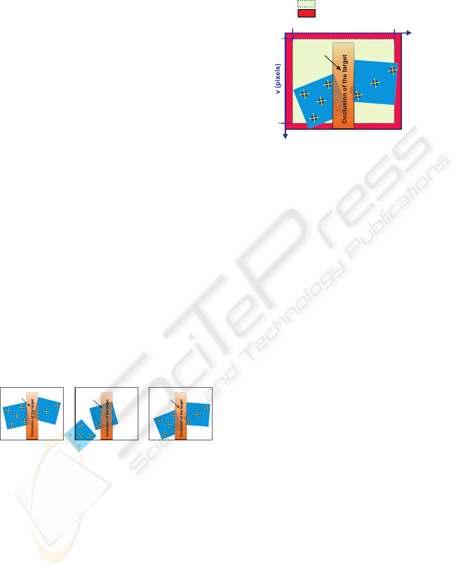
When the appearance/disappearance of features, it
is no produced through the border of the image, for
instance, due to a temporary occlusion of the features
(Figure 1, features number 3, 6, 7 and 8). The solution
proposed in (Garcia-Aracil and Malis, 2004) must be
adapted to assure the continuity of the control law.
We propose to use two new weights functions to take
into account this situation: one of them for the disap-
pearance of features near the center of the image Φ
i
o
(Figure 2, green zone) and the other one for the ap-
pearance of features near the center of the image Φ
i
a
(Perez et al., 2005).
1
2
3
4
5
6
7
8
Noborder(weightnotequatto0)
Border(weightequatto0)
u
min
u(pixels)
u
max
v
min
v
max
Object
Figure 2: The temporary disappearance concept in vision-
based control task.
The global weight function Φ
i
which includes the
three possible situations commented before is defined
as the product of the three weight functions (Φ
i
uv
, Φ
i
a
y Φ
i
o
):
Φ
i
= Φ
i
uv
· Φ
i
a
· Φ
i
o
where Φ
i
∈ [0, 1] (1)
2 THE SUDDEN
DISAPPEARANCE OF
FEATURES ON THE CENTER
OF THE IMAGE
In this case, the weight Φ
i
o
takes into account this sit-
uation and after a certain number of steps, this weight
reaches its minimum value 0. During the steps needed
to reach its minimum, the coordinates of image fea-
tures must have a value near their last value. The au-
thors think that we have only two possibilities: the
first one is to suppose that the coordinates of the im-
age features change slowly and they have their last
value during the needed steps so that the weight Φ
i
o
reachs its minimum value;the second one is using a
prediction filter to predict the next values of the image
features during the needed steps so that the weight Φ
i
o
reachs its minimum value. After a huge number of
simulations, we realize that a prediction filter option
is better than considering the last value of image fea-
ture.
We have tested the following prediction filters:
Linear Interpolation
The simplest analyzed filter is the Linear Interpo-
lation. This one is base on prediction calculus of the
next position aligned with two immediately previous
positions.
The Kalman filter
This filter is recommended for systems affected by
noise disturbance that cannot be modeled. It makes
THE VISIBILITY PROBLEM IN VISUAL SERVOING
483

a Bayesian prediction of the state where the system
model includes two random variables (Gaussian
variables) with null average and a well-known
covariance (white noise), these variables corresponds
to: the system error v(k) and the measure error w(k).
The Kalman filter is based on a recursive expression
of prediction and correction: it considers the current
state from the prediction and adds a term of pro-
portional correction to the prediction error, so this
prediction error is minimized (optimal estimation).
Alphabeta filter
The alpha-beta filter is a particular case of the
Kalman filter for a constant velocity system model.
In this case, the filter gain is considered constant, so
it is not calculated for each iteration. Also, it is not
necessary the calculus of covariance of estimation
and prediction of innovation simplifying the algo-
rithm and decreasing the calculus time.
Alphabetagamma filter
The alpha-beta-gamma (αβγ) filter is again a par-
ticular case of the Kalman filter, but in this case, it is
a filter based on a constant acceleration model system.
OLOF filter
The OLOF filter is a new filter designed at Miguel
Hernandez University and the authors think that the
use of this filter is recommended if the behavior of
the object is unknown a priori and probably the object
would have speed, acceleration and jerk changes.
The OLOF filter is a ”mix” of some other filters
(LI, αβ, αβγ, Kv (v=cte), Kv (a=cte)and Kv (j=cte)).
Starting with the same weights for each filter, a mod-
ification of Rosenbrock optimization algorithm was
used to adjust these parameters to the optimum val-
ues (Gill et al., 1981)(Rosenbrock, 1960)(Conn et al.,
1998). After different simulations we have obtained
the optimal values.
3 EXPERIMENTAL RESULTS
Experimental results has been obtained using a 6 axis
industrial manipulator (Fanuc LR Mate 200iB). The
experimental setup used in this work also include one
camera (Ueye Industrial camera from IDS) rigidly
mounted at the robot end-effector and some surgical
objects.
3.1 Control Law
Suppose that n matched points are available in the
current image and in the reference features stored.
Everyone of these points(current and reference) will
have a weight Φ
i
which can be computed as it’s shown
in the previous sections. With them and their weights,
a task function can be built:
e = CW (s − s
∗
) (2)
where W is a (2n × 2n) diagonal matrix where its
elements are the weights Φ
i
of the current features.
The derivate of the task function will be:
˙e = CW ˙s + (C
˙
W +
˙
CW)(s − s
∗
) (3)
Plugging the equation (˙s = L v) in (3) we obtain:
˙e = CW Lv + (C
˙
W +
˙
CW)(s − s
∗
) (4)
A simple control law can be obtained by imposing the
exponential convergence of the task function to zero
(˙e = −λe), where λ is a positive scalar factor which
tunes the speed of convergence:
v = −λ (CWL)
−1
e − (CWL)
−1
(C
˙
W +
+
˙
CW) (s − s
∗
) (5)
if C is setting to (W
∗
L
∗
)
+
,then (CWL) > 0 and
the task function converge to zero and, in the absence
of local minima and singularities, so does the error
s−s
∗
. In this case, C is constant and therefore
˙
C = 0.
Finally substituting C by (W
∗
L
∗
)
+
in equation (5),
we obtain the expression of the camera velocity that
is sent to the robot controller:
v = −(W
∗
L
∗
)
+
(λ W +
˙
W) (s − s
∗
) (6)
3.2 Results
We compare the weighted and un-weighted 2D visual
servoing approaches. In this experiment, the interac-
tion matrix is assumed constant and determined dur-
ing off-line step using the desired value of the visual
features and an approximation of the points depth at
the reference camera pose. The goal of the control is
to keep the robot in the reference position using the
2D visual servoing approach.
Using the 2D visual servoing approach, the system
becomes unstable due to the lost of a feature during
the control task(Figure 3(a)3(b)). When the 2D visual
servoing approach with weighted features is used, the
system is stable although one or more features leave
the image plane or something occlude one or more
features(Figure 3(c)3(d)).
4 CONCLUSION
In this paper, the visibility problems in visual servo-
ing are presented and a review of the different scien-
tific works which treat this problem are recalled. Af-
ter that, our solution to this problem is presented and
extended to the case of the sudden disappearance of
ICINCO 2006 - ROBOTICS AND AUTOMATION
484
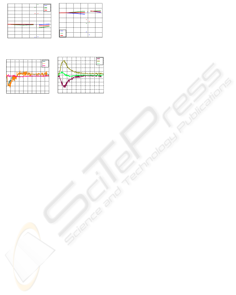
0 5 10 15 20 25 30
−0.8
−0.6
−0.4
−0.2
0
0.2
0.4
0.6
0.8
1
1.2
Iterations number
ω (rad ⋅ s
−1
)
ω
x
ω
y
ω
z
(a) Rotational velocity
0 5 10 15 20 25 30
−1
−0.8
−0.6
−0.4
−0.2
0
0.2
0.4
Iterations number
v (m ⋅ s
−1
)
v
x
v
y
v
z
(b) Translational velocity
0 20 40 60 80 100 120 140 160 180 200
−0.07
−0.06
−0.04
−0.02
0
0.02
0.04
0.06
0.07
Rotation speed
Iterations number
ω
ω
x
ω
y
ω
z
(c) Rotational velocity
(Weighted features)
0 20 40 60 80 100 120 140 160 180 200
−0.1
−0.08
−0.06
−0.04
−0.02
0
0.02
0.04
0.06
0.08
0.1
Traslation speed
Iterations number
v
v
x
v
y
v
z
(d) Translational velocity
(Weighted features)
Figure 3: Experimental results: 2D visual servoing ap-
proach.
features on the center of the image. To assure the con-
tinuity of the control law in this case, a prediction fil-
ter developed by us is used to estimate the coordinates
of the occluded image features. With the experimen-
tal results, it has been shown that the 2D visual servo-
ing with weighted features is continuous and locally
stable in a neighborhood of the equilibrium point.
ACKNOWLEDGEMENTS
This work has been supported by the Spanish Govern-
ment through the ’Comision Interministerial de Cien-
cia y Tecnologa’ (CICyT) through project ”T
´
ecnicas
avanzadas de teleoperaci
´
on y realimentacin sensorial
aplicadas a la cirug
´
ıa asistida por robots” DPI2005-
08203-C02-02 and the Valencia Government trough
the project ”Desarrollo de T
´
ecnicas avanzadas de real-
imentacion sensorial aplicadas a Cirug
´
ıa Asistida por
Robots” GV05/192.
REFERENCES
Benhimane, S. and Malis, E. (2003). Vision-based con-
trol with respect to planar and non-planar objects us-
ing a zooming camera. In IEEE International Con-
ference on Advanced Robotics, volume 2, pages 991–
996, Coimbra, Portugal.
Chesi, G., Hashimoto, K., Prattichizzo, D., and Vicino,
A. (2002). Keeping features in the camera field of
view:a visual servoing strategy. In 15th Int. Symp.
on Mathematical Theory of Networks and Systems,
Notre-Dame, Indiana.
Conn, A., Scheinberg, K., and TointMalis, P. (1998).
A derivative free optimization algorithm in practice.
In Proc., 7th AIAA/USAF/NASA/ISSMO Symposium
on Multidisciplinary Analysis and Optimization, St
Louis, USA.
Corke, P. and Hutchinson, S. (2001). A new parititioned
approach to image-based visual servo control. IEEE
Trans. on Robotics and Automation, 17(4):507–515.
Cowan, N., Weingarten, J., and Koditschek, D. (2002). Vi-
sual servoing via navigation functions. IEEE Trans.
on Robotics and Automation, 18(4):521–533.
F.Schramm and G.Morel (2004). A calibration free ana-
lytical solution to image points path planning that en-
sures visibility. In IEEE International Conference on
Robotics and Automation, volume 1, New Orleans,
USA.
Gans, N. R. and Hutchinson, S. (2003). An experimen-
tal study of hybrid switched system approaches to
visual servoing. In IEEE International Conference
on Robotics and Automation, volume 1, pages 3061–
3068, Taipei, Taiwan.
Garcia-Aracil, N. and Malis, E. (2004). Preserving the con-
tinuity of visual servoing despite changing image fea-
tures. In In Proc. IEEE/RSJ International Conference
on Intelligent Robots and Systems, Sendai, Japan.
Gill, P. E., Murray, W., and W y Wright, M. H. (1981).
Practical optimizacion. Academic Press.
Malis, E. (2004). Visual servoing invariant to changes in
camera intrinsic parameters. IEEE Transaction on
Robotics and Automation, 20(1):72–81.
Malis, E. and Chaumette, F. (2002). Theoretical improve-
ments in the stability analysis of a new class of model-
free visual servoing methods. IEEE Transaction on
Robotics and Automation, 18(2):176–186.
Mezouar, Y. and Chaumette, F. (2003). Optimal camera
trajectory with image-based control. Int. Journal of
Robotics Research, 22(10):781–804.
Morel, G., Liebezeit, T., Szewczyk, J., Boudet, S., , and
Pot, J. (1999). Explicit incorporation od 2d constraints
in vision based control of robot manipulators. In
Int.Symposium on Experimental Robotics, volume 1,
Sidney, Australia.
Perez, C., Garcia-Aracil, N., Azorin, J., Sabater, J., and
Navarro, L. (2005). Image-based and intrinsic-free vi-
sual navigation of a mobile robot defined as a global
visual servoing task. In 2nd International Conference
on Informatics in Control, Automation and Robotics,
Barcelona, Spain.
Rosenbrock, H. (1960). An automatic method for finding
the greatest or least value of a function. Comp. J.,
(3):175–184.
Zhang, H. and Ostrowski, J. P. (2002). Visual motion plan-
ning for mobile robots. IEEE Trans. Robotics and Au-
tomation, 18(2):199–208.
THE VISIBILITY PROBLEM IN VISUAL SERVOING
485
