INTELLIGENT SIMULATOR DESIGN FOR DISTRIBUTED
PIPELINE NETWORKS CONTROL
Yong Xu
Department of compute Science, Guilin University of Electronic Technology, China
Keywords: Scada, Modelling, Pipelines, Intelligent Control.
Abstract: Supervisory Control and Data Acquisition (SCADA) systems are widely used to meet the ever-increasing
technological demands for monitoring and control of distributed system. An intelligent simulator is
designed to enhance the conventional SCADA system. The new architecture can be exploited to develop
integrated systems for complex distributed system management, performance prediction, fault detection and
optimized operation.
1 INTRODUCTION
SCADA (Supervisory Control and Data Acquisition)
systems use computers and communication
technologies to automate the monitoring and control
of distributed systems and processes. Use of SCADA
systems improves the efficiency of the monitoring
and control process by providing timely information
so that appropriate operational decisions can be
made. Examples of traditional complex distributed
systems are pipeline systems in irrigation, water, gas
and oil industries (Mareels, 2004), (Dieu, 2001)
(Nitivattananon,
1996). Increasingly, SCADA system
can be found in manufacturing, petrochemical and
power plants (Albert, 2003) (Shen and Hsu, 1999),
factory automation, building automation, complex
pipeline systems and traffic management systems
(Gieling, 1996) (Moten, 1997). These systems
integrate geographically distributed units with
different functions. Computers and various control
and measuring modules are widely employed to
ensure these systems are efficiently managed, well
monitored and maintained under adverse conditions.
However, the initial investment for a full-featured
SCADA system can be high in terms of hardware,
software and staff training and consequently the
knowledge acquisition from the target system are
limited. The main reasons may due to:
1) the quantity and quality of the sensors are
limited;
2) the acquisition of adequate system knowledge
may be either incomplete or impractical due to
system complexity and/or due to the change in
system parameters over a period of time;
3) information from the physical system always
involves some uncertainty as noise and device
malfunction may lead to information inconsistencies
and even conflicts;
4) control and management strategy can not be
tested and evaluated before used in real system.
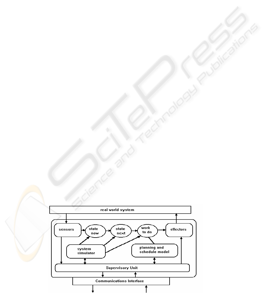
Figure 1: Intelligent SCADA system architecture.
182
Xu Y. (2006).
INTELLIGENT SIMULATOR DESIGN FOR DISTRIBUTED PIPELINE NETWORKS CONTROL.
In Proceedings of the Third International Conference on Informatics in Control, Automation and Robotics, pages 182-185
DOI: 10.5220/0001202701820185
Copyright
c
SciTePress
The proposed SCADA system architecture uses a
simulator to enhance the information acquisition
capacity of the SCADA system. The design and
operating principles of the simulator will be
discussed.
Simulation is used as an alternative and
complementary of the real system and the
dependencies of system parameters and variables.
Use of models with the SCADA system for the plant
or processes can improve the performance of the
SCADA systems while keeping the implementation
and running cost down. Therefore models are widely
used and have been proved as successful approach
(Kingsley, 2004) (Hernebring, 2002) (Demey, 2001)
(Turner, 1991).
The simulator plays two main roles. Firstly it can
predict how the real system would behave as initial
conditions, attributed values and relationships are
systematically varied. Combined with the sensory
system, the simulator provides a reliable and real-
time representation of the real world system.
Secondly, the system simulator can also be used
as a virtual system for testing and examining the
effects of different operational strategies. By
providing system information under varied operation
conditions, the system simulator is in essence a
knowledge generator where its data stream is
available for further exploitation. Typically this may
be used as a reference in decision making at an
operator level as well as in many activities at a
management level.
2 MODEL-BASED SCADA
SYSTEM ARCHITECTURE
The architecture of the SCADA system with a
simulator is illustrated in Figure 1. It integrates the
SCADA components with the simulation, decision
and optimisation components.
Intelligent real-time systems must make high-
level decisions and diagnose unexpected events
based upon the knowledge base. They acquire data
automatically, apply heuristic methods to interpret
sensor readings and feed advice out to the process or
up to the user. Such a system can evolve from
conventional SCADA systems by adding system
simulator and intelligent reasoning modules.
Methods used for control system design should use
both algorithmic-numeric methods and symbolic
methods. The former based on conventional control,
identification, estimation and communication
theories developed for continuous-state type
systems, and the latter used for knowledge base
processing, reasoning and decision making.
3 DEVELOPMENT OF SYSTEM
SIMULATOR
3.1 System Simulator Concept
A system is characterized by a set of attributes, or
quantities that assume values. Static attributes have
fixed values and are called the parameters of the
system. Dynamic attributes can assume different
values at different times at different points in space
and are known as the state variables of the system.
The system simulation approach adopted can be very
different depending on the developer preference and
on the target system. The approach described in this
paper is a general-purpose method but with
implementation emphasis to a continuous process
system such as a flow pipeline system. Typical
examples of static attributes in pipeline systems are
the geometric parameters of pipes while common
state variables are pressure and flow rate.
In terms of variable scope, there are two types of
state variables. These are interface variables, which
have interactions with the environment, and internal
variables, which have no direct interaction with the
environment. The interface variables can be further
classified into input and output variables. Internal
variables represent the internal condition of the
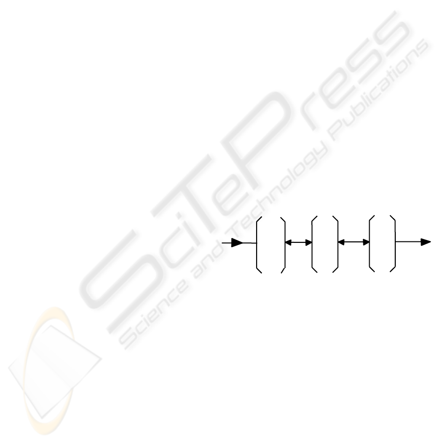
system. These variables are illustrated in Figure 2
and defined as equations (1) to (3):
Figure 2: Conceptual model of a system.
(
)
(
)
(
)
{
()
}
12 m
u ,u , ...,uttt t
=
∈uU
(1)
(
)
(
)
(
)
{
()
}
12 q
y ,y , ...,yttt t
=
∈
y
Y (2)
(
)
(
)
(
)
{
()
}
12 n
x ,x , ...,xttt t
=
∈xX (3)
where U, X and Y are understood to be the range
sets of the input, state and output variables.
The state variables are any set of variables with
following properties:
1. There exists an output function λ:x→y defined
for all t
i
in the time base that maps current states into
current outputs;
2. There exists a state transition function
δ:(X,U)→X defined for all [t
i
,t
j
] in the time base
that maps current states and inputs into future states.
y
y
.
.
y
1
2
q
u
u
.
.
u
1
2
x
x
.
.
x
1
2
n
m
INTELLIGENT SIMULATOR DESIGN FOR DISTRIBUTED PIPELINE NETWORKS CONTROL
183

The structure of a system is the relationships among
the input, state and output variables of a system that
give rise to its behaviour. A system, therefore, can be
completely defined by the algebraic structure
<U,X,Y,δ,λ,t>.
A mathematical model is used attempting to
quantify the attributes and to relate the components
mathematically. If a system S has the structure
<U,X,Y,δ,λ,t>, then a model of S is just some other
system S' with structure <U',X',Y',δ',λ',t'>. The
system S' is used as a substitute to study how the real
system would behave as initial conditions, attribute
values and the relationships are varied
systematically.
3.2 Object-Oriented Modelling
Object-oriented paradigm is used for dynamic
system analysis and control design for different
applications.
The basic unit in the model class hierarchy is
termed a Node and can be represented using the
notation shown in Figure 3.
Figure 3: Node notation
A Node is a model of a real-world entity
associated with a unique identifier. A Node consists
of two groups of elements: a defined set of attributes
(states) and a group of methods, commonly
implemented procedures or functions, allowing the
Node to perform various tasks.
All the node descriptive state variables are
grouped as internal variables and interface variables,
the former used for interaction with external objects
and the latter, the internal ones are private, hidden
within the node.
Nodes can be connected by coupling functions of
interface variables to form a system described by
another node, whose internal variables are only those
interface variables of the sub-nodes. In this way a
hierarchical structure model representing a complex
system can be established step by step and part by
part. The different subsystems can be analysed
separately to meet varying requirements in terms of
speed or precision.
A complex SCADA system may involve a great
number of variables in order to describe the system
for a specific requirement. Using the network of
nodes model, all the descriptive state variables are
grouped as internal variables inside the nodes with
interface variables being used for interaction
between the objects.
4 CASE STUDY: SIMULATION OF
PIPELINE SYSTEM
Pipeline system is a collection of components
including pumps, pipes, valves and filters, etc. and
can be perfectly represented using Node collection
model in a class hierarchy. In pipeline systems there
are only two basic flows, namely fluid flow and
information flow, where the fluid carries energy. The
information flow can be narrowly defined as the data
flow from sensors to the central processor unit and
that from the central processor to the actuators via
the communication network.
All the descriptive state variables are grouped as
internal variables inside the objects with interface
variables being used for interaction of the objects.
These subsystems are interconnected together by the
coupling functions of the interface variables.
As an example, in simulating components with
lumped parameters, such as most valves, connectors
and filters, the static characteristic can be used for
calculation. For pipes with considerable lengths the
distributed parameter, dynamic model has to be used
to meet the accuracy requirements. In applications
where state transience is involved, the transient flow
conditions have to be considered. In a real-time
control application, the component behaviour can be
predicted by a simple input-output map, which may
be a result of several weeks’ previous finite-element
analysis or neural-network model training.
When conditions such as initial condition and
boundary conditions being solved, all the system
state variables can be determined.
The validity and accuracy of the simulator can be
verified by system monitoring data from the sensory
system. Some successful models have been
developed for dynamic flow systems involve water
flow and air flow. The further details of these works
are reported by the author before (Xu, 1997) (Miller,
2000). Some applications in distributed process
control were also reported (Xu, 2004) (Pham, 2002).
Interface
--variables
--functions
Internal attributes
--variables
--functions
Node ID
ICINCO 2006 - SIGNAL PROCESSING, SYSTEMS MODELING AND CONTROL
184

5 INTEGRATION OF
DISTRIBUTE OBJECTS
Aided with simulator and intelligent functions, the
systems are no longer being viewed as simply
operational and engineering tools, but quasi-
autonomous decision-makers. In this role they
continue to serve as the centre for operational
responsibility, but also provide data to systems and
users outside of the control centre environment who
depend upon timely information on which to base
day-to-day business decisions.
A full solution of intelligent SCADA will also
contain the following components/modules:
z distributed I/O with real-time data exchange
(networked data acquisition and control);
z batch control and executions;
z remote network management;
z multimedia user interface (large screen
terminals etc.)
To fully exploit the potentials the intelligent
SCADA system can offer, the system needs also
considerations on:
z assure security, data protection and access
management;
z redundant system components for reliability;
z the proper infrastructure framework for
information exchange (e.g. Internet protocol
applications).
6 CONCLUSIONS
The basic idea of a simulator enhanced intelligent
SCADA system architecture is introduced. The
concept of a simulator of a long-distance pipeline
system and its implementation approach are also
briefly mentioned.
The main features of the proposed system
simulator are as follows:
1. Hierarchical structured: The object orientation
of the model system and software architecture allows
the complex system be built and upgraded gradually.
2. Evolutionary: The system may evolve by
adding more specialised and modules. New objects
can be introduced. With several identical simulators
(or several copies of the simulator) available at
different phases of development, the performance of
the system can be improved continuously without
breaking the working life cycle.
3. Intelligent: The uncertainty in physical systems
can be dealt with using modern statistical methods,
fuzzy models and neural network techniques. The
system can learn from experience and update its
memory. The AI level of the decision making
process can be developed to make the whole system
highly intelligent.
REFERENCES
Demey, D, et al., Validation and implementation of model
based control strategies at an industrial wastewater
treatment plant, Water Science and Technology: a
Journal of the International Association on Water
Pollution Research, Volume 44, Issue 2-3. (2001)
Dieu, B, Application of the SCADA system in wastewater
treatment plants, ISA Transactions, Volume 40, Issue
3, (2001)267-281.
Gieling ThH; van Meurs WTh; Janssen, H J, A computer
network with SCADA and case tools for on-line
process control in greenhouses, Advances in Space
Research: the Official Journal of the Committee on
Space Research (COSPAR), Volume 18, Issue 1-2.
(1996)
Hernebring, C; Jönsson, L E; Thorén, U B; Møller, A,
Dynamic online sewer modelling in Helsingborg,
Water Science and Technology: a Journal of the
International Association on Water Pollution Research,
Volume 45, Issue 4-5,(2002)
Kingsley E. Abhulimen and Alfred A., Liquid pipeline
leak detection system: model development and
numerical simulation, Chemical Engineering Journal,
Volume 97, Issue 1. (2004)
Mareels, I, et al., Systems engineering for irrigation
systems: Successes and challenges, Annual Reviews in
Control, Volume 29, Issue 2, (2004)
Miller, M. R.; et al, 2000, Peak Expiratory Flow Profiles
Delivered by Pump Systems: Limitations due to Wave
Action, American Journal of Respiratory and Critical
Care Medicine, vol. 161, no. 6, (2000)
Nitivattananon, V., et al., Optimization of Water Supply
System Operation, Journal of Water Resources
Planning and Management, Vol. 122 No. 5.(1996)
Pham, D T, Xu, Y., Internet Enabled Total Automation-
Integration of Distributed Tasks in Manufacturing
Enterprises, the 15th IFAC World Congress b'02,
Spain, (2002).
Turner, W. J. Kwon, P. S-J.and Maguire, P. A., Evaluation
of a gas pipeline simulation program, Mathematical
and Computer Modelling, Volume 15, Issue 7, (1991).
Xu, Y., Web-based Enterprise Automation System Design
for Feed Industry, Computing Technology and
Automation, 2004-No.4 (in Chinese),,(2004).
Xu, Y., "A Dynamic Hierarchical Model for complex
pipeline systems, Proceedings of 2nd Inter. Confer. on
Pipeline Systems, Hague, Netherlands, (1997).
INTELLIGENT SIMULATOR DESIGN FOR DISTRIBUTED PIPELINE NETWORKS CONTROL
185
