
FAULT MAINTENANCE IN EMBEDDED SYSTEMS
APPLICATIONS
Multiple Lift Control System as Safety Critical Embedded Application
Miroslav Sveda
Faculty of Information Technology, Brno University of Technology, Bozetechova 2, 61266 Brno, Czech Republic
Radimir Vrba
Faculty of Electrical Engineering & Communication, Brno University of Technology, Brno, Czech Republic
Keywords: Embedded system design, System architecture, Fault maintenance, Fail-stop safety model.
Abstract: This paper describes principles of a designed multiple lift control system based on a dedicated embedded
architecture. After reviewing dependable concepts used, the main attention is focused on the design of
hardware architecture, software, and communication services and protocols fitting the application
requirements. The multiple lift control system presents in this case a real-world solution of a safety critical
embedded system application. The design employs a fail-stop safety model and dedicated distributed
architecture to meet application requirements efficiently. The paper stresses those features that distinguish
the real project from a demonstration case study.
1 INTRODUCTION
Requirements on current embedded system
applications include both functional and non-
functional requirements on real-time behaviour and
safety properties (Leveson, 1984) that can be
formally specified and verified or, at least, properly
explored before they are designed in detail and
implemented. After reviewing utilized dependable
concepts, the main attention of this paper is focused
on hardware and software architecture of the
developed system, and on communication services
fitting the application domain.
2 DEPENDABILITY
The design of current embedded system applications
should consider not only functionality but also
dependability measures. Functionality means
services delivery in the form and time fitting
requirement specifications, where the service
specification is an agreed description of the expected
service. Functionality properties should be realized
efficiently and cost-effectively, so reachable
performance and maintainability of implementation
belong to the checked properties.
Dependability is that property of a system that
allows reliance to be justifiably placed on the service
it delivers. A failure occurs when the delivered
service deviates from the specified service.
Dependability measures consist of reliability,
availability, security, safety and survivability.
Availability is the ability to deliver shared service
under given conditions for a given time, which
means elimination of denial-of-service
vulnerabilities. Security is the ability to deliver
service under given conditions without unauthorized
disclosure or alteration of sensitive information.
Security attributes add requirements to detect and
avoid intentional faults.
Safety is the ability to deliver service under
given conditions with no catastrophic affects. Safety
attributes add requirements to detect and avoid
catastrophic failures. A failure occurs when the
delivered service deviates from the specified service.
An error is that part of the system state which is
liable to lead to failure. The cause of an error is a
fault. Failures can be classified according to
183
Sveda M. and Vrba R. (2006).
FAULT MAINTENANCE IN EMBEDDED SYSTEMS APPLICATIONS - Multiple Lift Control System as Safety Critical Embedded Application.
In Proceedings of the Third International Conference on Informatics in Control, Automation and Robotics, pages 183-186
DOI: 10.5220/0001202501830186
Copyright
c
SciTePress
consequences upon the environment of the system.
While for benign failures the consequences are of
the same order of magnitude (e.g. cost) as those of
the service delivered in the absence of failure, for
malign or catastrophic failures the consequences are
not comparable.
A fail-safe system attempts to limit the amount
of damage caused by a failure. No attempt is made
to satisfy the functional specifications except where
necessary to ensure safety. A fail-stop system never
performs an erroneous state transformation due to a
fault (Schneider, 1983). Instead, the system halts and
its state is irretrievably lost. The fail stop model,
originally developed for theoretical purposes,
appears as a simple and useful conception
supporting the implementation of some kinds of fail-
safe systems. Since any real solution can only
approximate the fail-stop behaviour and, moreover,
the halted system offers no services for its
environment, some fault-avoidance techniques must
support all such implementations.
3 APPLICATION
While a lift control system offers a classical example
used in literature for presenting principles of
requirements elicitation (Lamsweerde, 1998),
simulation (Knuth, 1969), formal specification
(Evans, 1994), validation (Valmari, 1987), design
verification (Cuellar et al., 1994), rapid prototyping
(Brink et al., 1993), and executable specification
(Hale, 1990), little attention is de-voted to
publishing the real world projects of this kind.
Nevertheless, such dedicated system, with a long
tradition of development, can demonstrate dedicated
solutions that have to conform to the strict
dependability requirements typical for safety-critical
applications.
3.1 Architectural Specifications
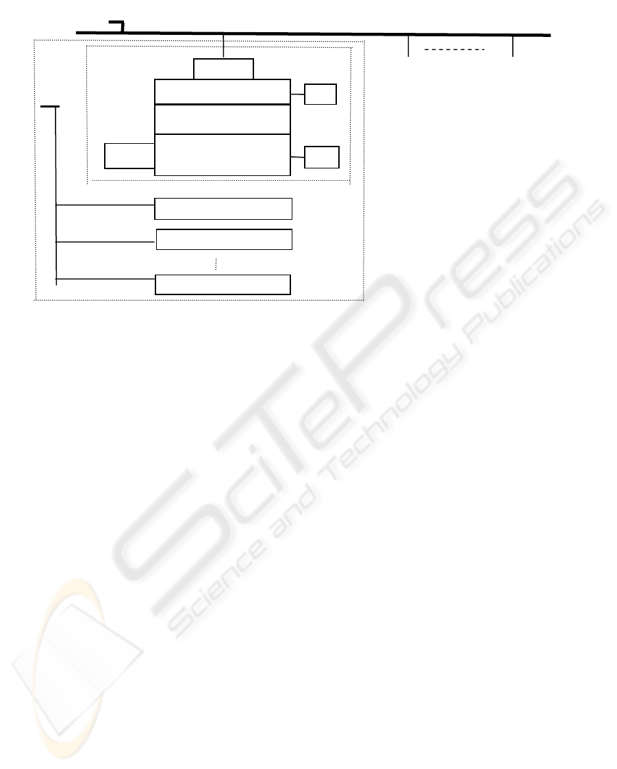
The multiple lift control system governs the
operation of N identical lifts servicing an M-storey
building, see Figure 1. For this purpose, it interacts
with its environment in the following way. Every lift
cabin includes a control panel with one button for
each floor, an emergency button, a key-lock handler
for attendant-mode traffic, and a numerical display.
These inputs/outputs should respect human
physiological constants. Other inputs and outputs in
the lift cabin involve load sensor, door driver, door
position detector, and gate optical barrier, of course,
with individual timing. On each floor (except ground
and top with modified configuration for border line
Dispatcher
External Serial Bus
LIFT
CONTROLLER
2
LIFT
CONTROLLER
N
Shaft
Controller
Comm
WD
WD
Comm
Scheduling Processor
Two-port RAM
Drive Control
Processor
Floor Controller M
Floor Controller M
Lift Cabin Controller
LIFT
CONTROLLER
1
Diagnostics
Internal Serisal Bus
Comm: Communication Processor
WD: Watchdog Processor
Figure 1: Multiple lift control system architecture.
ICINCO 2006 - INTELLIGENT CONTROL SYSTEMS AND OPTIMIZATION
184

positions) there are two buttons, one to request a lift
going upwards and the other for going downwards,
and moreover course lights, time interval display
and acoustic signalization with the same timing
requirements as mentioned above for the lift cabin
control panel. The position and speed of each lift is
measured and controlled by a lift drive. This group
of in-puts/outputs requires special attention because
of hard real-time limits.
The control system architecture stems from the
following conception. The external serial bus
interconnects N identical lift controllers and a
dispatcher station; in addition, each lift controller
embodies a dedicated distributed system with
internal serial bus connecting a shaft controller, M
floor controllers, and a cabin controller. The shaft
controller, which is a dedicated multiprocessor,
comprises one scheduling processor and one drive
control processor communicating through a common
memory, two communication processors enabling
access to external and internal serial buses, and two
simple watchdog processors.
3.2 Functional Specifications
The behaviour of each lift is directed by its
scheduling processor using both global master
directives, which consider orders from floors
provided through a floor controller and local orders
from the lift cabin provided through a cabin
controller -- the global master, elected among all
active scheduling processors during the initialization
phase -- obtains also information about orders from
all cabins to improve task allocation efficiency. For
each shaft controller, a scheduling processor and a
drive control processor share, in two-port RAM, data
structures describing the state (position, speed,
direction, load, and error status), list of orders to be
serviced including allowed time limits, and the next
serviced floor.
Possible traffic modes implement a self-service
administration with various N-lift scheduling
strategies and a separate lift self-service or attendant
management including also such special policies as
maintenance and fire brigade support. While the
scheduling processor communicates with the global
master and, accordingly, updates the orders from
floors, the drive control processor controls the lift
position and speed and updates the lift state and
cabin orders. The lift cabin controller serves the
control panel and the load sensors and manages the
door drive respecting the door position, the drive
moment, and the gate optical barrier. Finally, the
floor controller serves floor buttons, course lights,
acoustic signalization of arriving lift, and display
with approximate time interval to floor tending.
The multiple lift control system is designed to be
fully observable and controllable through its serial
buses. In a special 'off-line' mode, every processor
can upload or download through the incident serial
bus its local data and local inputs or outputs. That
feature administered by relevant modes of the
dispatcher and diagnostic station behaviour props
installation and repair of the control system. Both
above mentioned stations can also emulate dedicated
network analyzers and management terminals.
While the dispatcher station can monitor, test, or
supervise the whole interconnected system, the
portable diagnostic station implements equivalent
functions for the individual lift controller. Such
property promotes both an adaptation of service
strategies and regular system maintenance.
After power supply initiation and successful
power-up tests of all processors including memories,
peripheries, and internal connections, the
communication processors incident with the external
interconnection elect, according to the lowest
address on external serial bus, the current global
master, which is responsible to allocate service tasks
to the individual lifts. This allocation follows a
strategy either prescribed by the dispatcher station or
selected by the global master according to the traffic
type of building serviced, week and month or season
day, and day or night time. When the external serial
bus is disconnected, the scheduling will proceed
locally.
The software of scheduling processors stems
from a real-time executive with pre-emptive task
planning based on fix priorities. The supervisor task,
which is periodically activated by a timer,
implements initialization, mode selection, and
extraordinary events services. The scheduler task,
which can be activated by a message, realizes global
and local scheduling of lift services. Other auxiliary
tasks support accessing and updating the lift data
model based on above mentioned data structures. As
for the drive control processors, their dedicated
software in foreground/background format
guarantees very short response times for speed and
position drive control loops and transfers, without so
strict temporal limits, information between the lift
data model and the lift cabin or floor controllers. In
each shaft controller, the communication controllers
implement corresponding, special purpose protocols
and release the execution processors from
communication loads. The lift cabin and floor
controllers fulfil the above stated functions using
polling loops.
FAULT MAINTENANCE IN EMBEDDED SYSTEMS APPLICATIONS - Multiple Lift Control System as Safety Critical
Embedded Application
185

3.3 Fault Maintenance Concepts
The methods used accomplish the fault management
in the form of (a) hazardous state reachability
control and (b) hazardous state maintenance. In safe
states, the lift cabins are fixed at any floors. The
system is allowed to reach any hazardous state when
all relevant processors successfully passed the start-
up checks of inputs and monitored outputs and of
appropriate communication status. The hazardous
state maintenance includes operational checks and,
for shaft controller, the fail-stop support by two
watchdog processors performing consistency
checking for both execution processors. To comply
with safety-critical conception, all critical inputs and
monitored outputs are doubled and compared; when
the relevant signals differ, the respective lift is either
forced (in case of need with the help of an substitute
drive if the shaft controller is disconnected) to reach
the nearest floor and to stay blocked, or (in the case
of maintenance or fire brigade support) its services
are partially restricted. The basic safety hard core
includes mechanical, emergency brakes.
Because permanent blocking or too frequently
repeated blocking is inappropriate, the final
implementation must employ also fault avoidance
techniques. The other reason for the fault avoidance
application stems from the fact that only
approximated fail-stop implementation is possible.
Moreover, the above described configurations create
only skeleton carrying common fault-tolerant
techniques see e.g. (Maxion et al., 1987). In short,
while auxiliary hardware components maintain
supply-voltage levels, input signals filtering, and
timing, the software techniques, namely time
redundancy or skip-frame strategy, deal with non-
critical inputs and outputs.
4 CONCLUSIONS
The multiple lift control system presents a real-
world solution of a safety critical embedded
application employing the introduced fail-stop safety
model and dedicated distributed architecture. The
specification and design of the multiple lift control
system, ordered and supported by a lift
manufacturer, were completed a couple of years ago.
For other than technical reasons the project was
cancelled before full implementation of the target
system and preparation of production stages. What
appears as an advantage in this not too optimistic
state of affairs is the fact that this situation enabled
to publish such details of the project that could not
be disclosed in the opposite case.
ACKNOWLEDGEMENTS
The research has been supported by the Czech
Ministry of Education in the frame of MSM
0021630503 Research Intention MIKROSYN: New
Trends in Microelectronic Systems and Nano-
technologies, and by the Grant Agency of the Czech
Republic through the grants GACR 102/05/0723: A
Framework for Formal Specifications and
Prototyping of Information System’s Network
Applications and GACR 102/05/0467: Architectures
of Embedded Systems Networks.
REFERENCES
Brink K., Huijsman R., van Katwijk J.: SEAL: A Simple
Language for Prototyping Action-Event
Specifications. Microprocessing and Micro-
programming, Vol. 38 (1993) 87-95.
Cuéllar J., Wildgruber I., Barnard D.: Combining the
Design of Industrial Systems with Effective
Verification Techniques. In: Naftalin M., Denvir T.,
and Bertran M. (Eds.): FME'94: Industrial Benefit of
Formal Methods, LNCS 873, Springer-Verlag, Berlin
(1994) 639-658.
Evans A.S.: Specifying & Verifying Concurrent Systems
Using Z. In: Naftalin M., Denvir T., and Bertran M.
(Eds.): FME'94: Industrial Benefit of Formal Methods,
LNCS 873, Springer-Verlag, Berlin (1994) 366-380.
Hale R.: Using Temporal Logic for Prototyping: The
Design of a Lift Controller. In: Zedan H.S.M. (Ed.)
Real-Time Systems, Theory and Applications, North-
Holland, Amsterdam (1990) 81-118.
Knuth D.E.: The Art of Computer Programming: Basic
Algorithms (Vol. 1), Addison-Wesley, London (1969).
van Lamsweerde A.: Inferring Declarative Requirements
Specifications from Operational Scenarios. Trans. on
Software Engineering, Vol. 24 (1998) 1089-1114.
Leveson N.G.: Software Safety in Computer-Controlled
Systems. IEEE Computer, February (1984) 48-55.
Maxion R. A., Siewiorek D. P., Elkind S. A.: Techniques
and Architectures for Fault-Tolerant Computing. Ann.
Rev. Comput. Sci., No. 2 (1987) 469-520.
Schneider F.B.: Fail-Stop Processors. COMPCON'83
SPRING, Digest of Papers 26th IEEE CS Int. Conf.
(1983) 66-70.
Valmari A.: Reachability Analysis-Based Validation of
Embedded Systems. Microprocessing and Micro-
programming, Vol. 21 (1987) 393-404.
ICINCO 2006 - INTELLIGENT CONTROL SYSTEMS AND OPTIMIZATION
186
