
TWO LAYER CONTROL STRATEGY
APPLIED TO BUILDING AUTOMATION
João Figueiredo
Universidade de Évora,CEM-IDMEC, R. Romão Ramalho, 59, 7000 Évora, Portugal
José Sá da Costa
Instituto Superior Técnico, IDMEC, Av. Rovisco Pais, 1049-001 Lisboa, Portugal
Keywords: Distributed Systems, Industrial Networks, SCADA Control and Monitoring.
Abstract: A two level hierarchical control strategy is developed over a network of distributed systems. This paper
shows the great potential of a control strategy over two layers - distributed local controls which are
connected with an intelligent centralized control, which has a global view over the system, and permits an
actualization of the local references, knowing the complete state of the entire system The tested prototype
worked perfectly showing the huge potential of communication systems between distributed processes.
These communication systems allow intelligent centralized algorithms to manage decision making problems
in real-time environments. The system presented in this paper combines several technologies (local PLCs,
SCADA systems and network communications) to reach the goal of efficient management of distributed
processes.
1 INTRODUCTION
Today with the worldwide communications
development it is more and more usual the
decentralized management of systems. This strategy
reaches different fields, from agriculture, to industry,
domotics ... (Christensen, 2002), (Dey, 1999),
(Figueiredo, 2005a).
In the economic field the big companies locate
plants in low-cost lands and research and
commercial activities close to customer
industrialized lands.
In engineering, especially in the industrial field,
the motivation to optimize resources, forces the
communication between decentralized systems in
order to reach better allocation of resources,
minimizing the waste of raw materials, reducing
production costs…
In this context the communication between
distant systems is increasing tremendously, not only
in new built systems but also when reengineering is
brought to old systems. The reengineering of old
plants brings new intelligence to these systems by
introducing automation solutions in their processes.
These new instrumentation systems (intelligent
sensors and actuators) allow the plants to
communicate their actual state to the centralized
control unit, allowing a real-time decision making
(Neto et al., 2004), (Ratinho, 2002).
In this paper an urban application of decentralized
control strategy is presented. A control and
monitoring platform for an Intelligent building is
developed using a SCADA system (Supervisory
Control And Data Acquisition). The control strategy
developed in this paper develops a two-level
architecture where inner-loops are performed by
local PLCs (Programmable Logic Controller), and
the outer-loop is managed by the centralized
SCADA system that interacts with the entire local
PLC network. The outer loop has the potential to
develop a more heavy control algorithm as the
current low-level control actions are managed by the
local PLCs. Tests on a prototype are shown. The
prototype represents a multi-input/output parking
place, composed by several gates distributed by
different building floors, and having a centralized
control unit that manages and monitors the complete
state of the parking place (current number of free
places, gates state, utilization percentage of each
210
Figueiredo J. and Sá da Costa J. (2006).
TWO LAYER CONTROL STRATEGY APPLIED TO BUILDING AUTOMATION.
In Proceedings of the Third International Conference on Informatics in Control, Automation and Robotics, pages 210-216
DOI: 10.5220/0001201802100216
Copyright
c
SciTePress
gate, overall power consumption, fire and smoke
alarms… All the instrumentation in place is
controlled by the industrial PLC network. Each PLC
unit controls a set of sensors and actuators,
responsible for the proper actuation of the input and
output gates located in a multi input-output parking
place.
2 SYSTEM MODEL
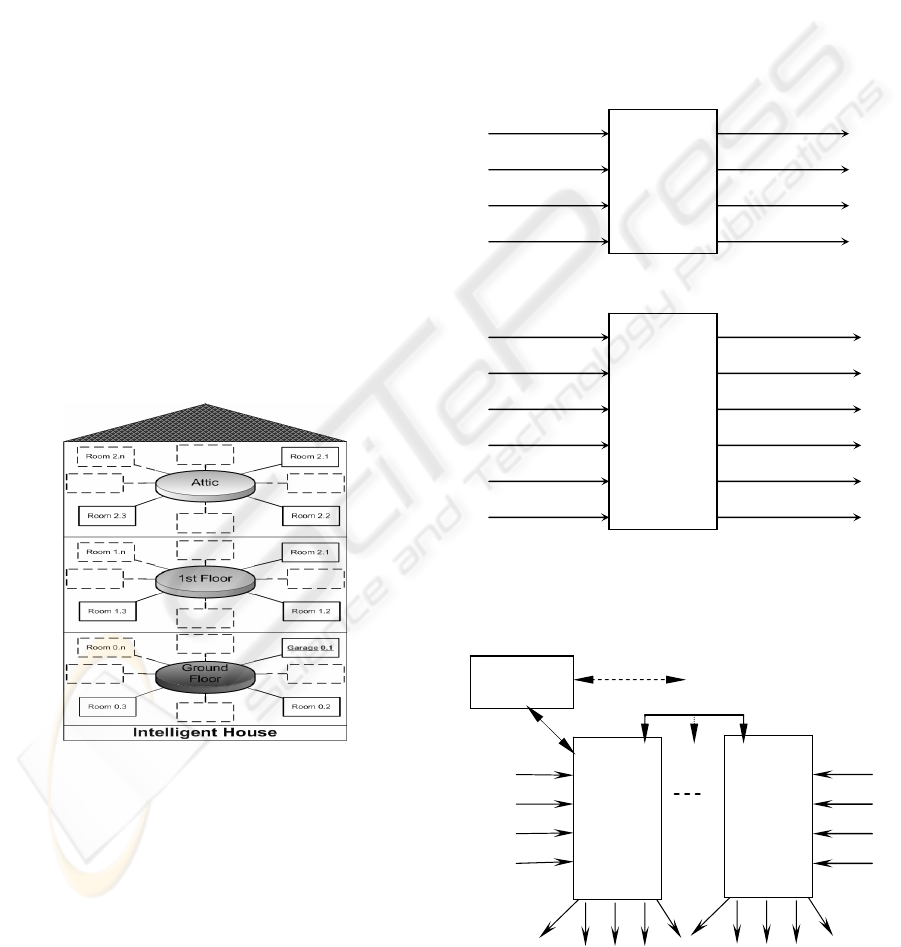
The studied building is modeled as tree-structure,
composed by two main sub-structures: Floors and
Rooms (Figueiredo, 2005b).
This structure provides flexibility to the model as
it can deal with both small/simple and big/complex
buildings (Fig. 1). Following this modular model
structure, each room is considered as an autonomous
unit with its independent monitoring and control
activities. The SCADA application is developed
according the model-tree structure presented above,
allowing the user to go down from the general state
view of the entire Building to each floor, descending
continuously to each room and reaching the final
elementary chain devices such as sensors or
actuators.
Figure 1: Intelligent Home as a tree-structure Model.
Each floor is modeled as a set of rooms and each
room has several sensors and actuators.
The set of actuators and sensors considered in
each room are mainly grouped into 2 groups:
- Group A: leaving rooms, bedrooms;
- Group B: kitchens, toilets, parking place.
The set of sensors and actuators considered in
both groups are shown in fig. 2.
An additional feature of this model that provides
the system huge accessibility to their users is the
SCADA platform where this model was
implemented which allows the system to be
connected trough the internet. This feature will be
presented in chapter 3.
Concerning the prototype tested in this paper, the
multi-input multi-output parking place, the
inputs/outputs considered in each gate are illustrated
in fig. 3. Additionally to the specific gate
inputs/outputs showed in fig. 3, there are also, in the
parking place all the sensors/actuators illustrated in
Group B, fig. 2.
Group A: sensors and actuators
Group B: sensors and actuators
Figure 2: Intelligent Home: Sensors and Actuators.
Figure 3: Parking Place Gate inputs/Outputs.
A
utomatic
System
(SCADA Axeda)
Start
Car In
Car Out
Reset
Master
System
Siemens
S7-300
Slave
System
Siemens
S7-300
Gate 1
PROFIBUS NET
MPI NET
Red
Green
N. In
N. Out
P. Full
INTERNE
T
Gate n
Start
Car In
Ca
r
Out
Reset
Group A
Lights sensors
Mov. sensors
Light actuators
Alarm actuators
Temp. sensors Air Cond. actuators
Smoke sensors Exhaust actuators
Group B
Lights sensors
Mov. sensors
Light actuators
Alarm actuators
Temp. sensors Air Cond. actuators
Smoke sensors Exhaust actuators
Water sensors
Gas sensors
Central Water supply
Central Gas supply
TWO LAYER CONTROL STRATEGY APPLIED TO BUILDING AUTOMATION
211
3 MONITORING AND CONTROL
STRATEGY
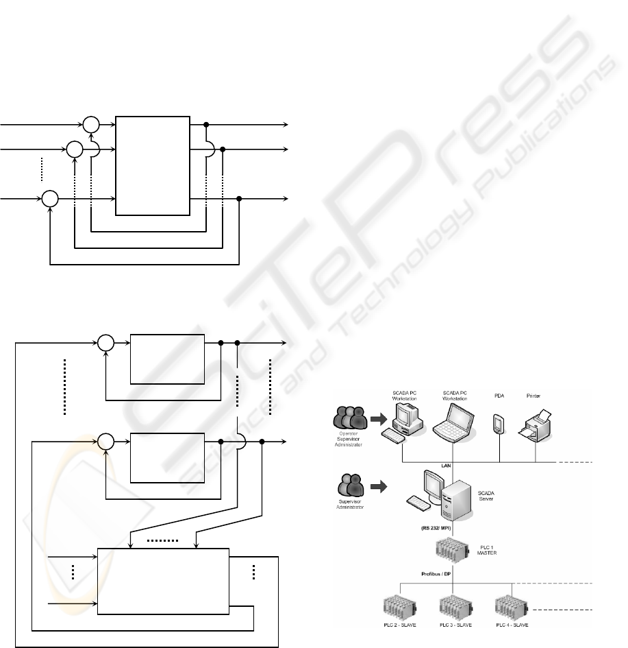
3.1 Control Strategy
The strategy developed in this paper is commonly
known as a two-level hierarchical control model as it
integrates a first control loop that is managed by
local PLCs with a second loop which is performed
by a SCADA supervisory system that monitors
globally the several distributed local systems
(Figueiredo, 2005b). Figures 4 and 5 illustrate this
control strategy: The inner control (first loop) and
the outer control loop.
Figure 4: First Loop Control – PLC Local Control.
Figure 5: Second Loop Control – SCADA Supervisor
Control.
Applying this strategy to a complex building that
is instrumented and monitored through a SCADA
supervisory system, we can manage globally the
entire net of field PLCs that control locally each own
process.
The upper level control law, having a global
system overview, generates the set of references for
each local process (PLC) avoiding possible conflicts
in emergency situations. The input functions for the
upper control loop are mentioned as comfort laws,
safety laws (F1(t), … ,Fj(t)).
3.2 PLC Network and SCADA
Supervisor
The developed strategy to cope with complex
buildings with a huge set of geographically
distributed actuators and sensors is implemented
through a PLC network (fig. 6) consisting of several
slaves PLCs connected to a master PLC via
Profibus/ DP network.
Each slave PLC hosts several control programs
which selection is made either locally, via an HMI
(Human Machine Interface) or remotely, via the
master PLC (PLC 0), which is connected to the
server PC, via RS232/ MPI Siemens protocol, where
the SCADA application is running.
The server PC is simultaneous a SCADA server
and an internet server, as the implemented SCADA
application is web enabled. All process variables are
available at the SCADA PC as these variables are
on-line available through the Profibus/ DP Master-
Slave network.
Figure 6: PLC Network and SCADA supervisor.
PLC
Ref 1.1
1
Ref 1.2
Ref 1.n
q 1.n
q 1.2
q 1.1
+
+
+
-
-
-
PLC
Ref 1.i
1
q 1.i
+
-
PLC
Ref k.i
k
q k.i
+
-
q 1.i q k.i
F1
(
t
)
F
j(
t
)
SCADA Su
p
erviso
r
Ref 1.i
Ref k.i
ICINCO 2006 - ROBOTICS AND AUTOMATION
212
3.3 SCADA Supervisory Control
Loop
System Description: The SCADA system used to
implement this monitoring and control strategy was
a commercial platform: Axeda Supervisor Wizcon
for Windows & Internet V 8.2.
The Driver used in this application to establish the
communication Scada system – Master-PLC was the
Siemens RS232/MPI interface, via the Siemens
software Simatic S7 Prodave. According to this
communication Protocol, a PLC digital variable
address must be defined as NNTXAAAABB, where:
NN = PLC address (from 0 to 32);
T = memory area type (I for Input, Q for
Output and M for memory);
X = variable type (B for Byte, W for Word);
AAAA = slot address (from 0000 to 9999);
BB = variable address (00 to 17).
In the specific case of the prototype tested in this
paper, it is necessary to exchange integer values
between the several local PLCs in order to update
the system overall capacity (actual number of free
places in the park).
The SCADA system receives continuously the
information from all PLCs in the network through
the master-PLC and calculates the number of free
places available in the parking place. This integer
values is on-line updated to the PLC network and
according this value the corresponding state of the
entrance lights (red/ green) is determined. When the
number of free places equals zero, the entrance red
lights in all the park gates are set on, until a car exits
the park. This car exit can take place from one of the
several available gates in the parking place.
The transfer of integer values between the
SCADA system, the master-PLC, and forward, to all
slave-PLCs, it is possible through Data Base
transfer. According to the MPI protocol, an integer
value to be transferred from the PLC to the SCADA
system and vice versa, it must be addressed as
NNTXDDDAAAA, where:
NN = PLC address (from 0 to 32);
T = memory area type (D for Data Block, I
for Input, Q for Output and M for
memory);
X = variable type (B for Byte, W for Word);
DDD = Data Block identification (from 000 to
999);
AAAA = variable byte address in Data Block.
Among the main functionalities of a SCADA
system there is the so called “Tag”. A “Tag” is a
defined variable that permits the exchange of
information between the PLC network and the
SCADA system, in a real-time environment. There
are usually three types of Tags: PLC, Dummy and
Compound. In the PLC Tags the PLC sets the
variable values that are directly transferred to the
Scada program. In the Dummy Tags the value is set
by the user on the Scada interface and transferred to
the PLC address. Finally Compound Tags are set by
the Scada program, following the programmed
operations.
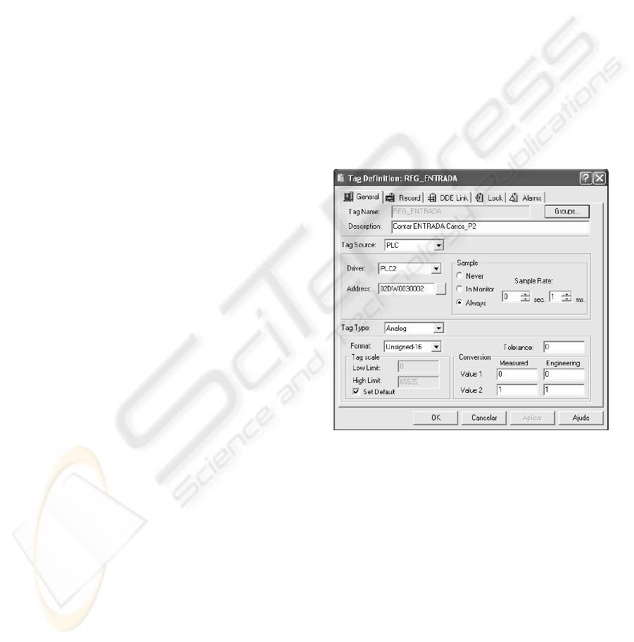
When defining the Tags a set of information is
required, namely: Tag name, Description, Tag
source, Driver, Sample rate, Address and Tag Type.
An example of such Tag definition is illustrated in
Fig. 7.
Figure 7: Tag definition.
The Scada main interface between the system and
the user are the application images. The image
building is a functionality of all SCADA systems
and its main function is to permit the user a quick
visual identification of all system functional
characteristics. An easy identification of the system
Inputs and Outputs permits the user an effective
monitoring and a quick actuation on the process,
when it is necessary.
The developed application used important
features that we named animated images. These
images change geometry characteristics and colours
when their digital variables change the state (on/
off).
TWO LAYER CONTROL STRATEGY APPLIED TO BUILDING AUTOMATION
213
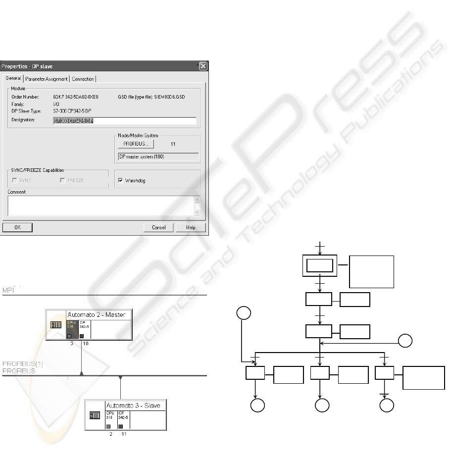
3.4 PLC Master-Slave Network
System Description: The PLCs used to implement
the local control strategy were the Siemens S7-3**.
The Siemens software used to implement the
PLC application was the Simatic Manager. The
program language used was the Ladder Diagram
(LAD).
A PLC master-slave network was established
through a Profibus protocol (Siemens, 2001).
The main characteristics of the PLC master-slave
network implemented in the prototype is shown in
fig 8. In fig. 9 the overall PLC network implemented
in this paper is presented.
Figure 8: Main characteristics of PLC Master-Slave
network.
Figure 9: Profibus Master-Slave network.
Local Control Strategy: At the local control level,
several algorithms have been developed for the
intelligent building: Property Violation, Temperature
control, Gas and Water leakages, parking gate
management…
Using the Grafcet methodology, the main
characteristics developed for the parking gate
management is presented below (fig. 10).
The input variables referred in fig. 10 represent:
Out = binary sensor indicating a vehicle that
wants to exit the park;
IN = binary sensor indicating a vehicle that
wants to enter in the park;
Free Place = integer value representing the
actual free places available in the park,
at each time.
The output variables referred in fig. 10
represent:
Green = Green light at the parking gate;
Red = Red light at the parking gate;
Gate = Gate actuator that closes and opens the
parking gate;
FP = Function Block that calculates the
actual Free Places in the Park. This
Function Block is associated with a
Data Base Block, which is accessed by
all PLCs connected in the PROFIBUS
network.
Figure 10: Grafcet for Parking gate management.
Together with this gate management system,
there are also other automatic systems running in the
local PLCs: property violation control, temperature
control…
0
3 4
OUT
*
Gate = ON
Call FP
1
Green = ON
Red = OFF
Start
Green = ON
Red = OFF
Gate = OFF
FP = max.
Call FP
2
Gate = ON
Call FP
Start. IN. FP = max
Gate = ON
Call FP
OUT. Free Place > 0 IN. Free Place > 0
5
Red = ON
Green = OFF
Gate = OFF
Free Place = 0
**
* * **
Reset
ICINCO 2006 - ROBOTICS AND AUTOMATION
214
4 EXPERIMENTAL SETUP
The developed application to monitor and control
intelligent buildings has been implemented in an
experimental setup to control a parking place with
multiple distributed entrances/exits.
The prototype developed has the following
software and hardware requirements.
4.1 Software Requirements
The Scada system was developed over the platform
Axeda Supervisor Wizcon for Windows & Internet
V8.2.
Siemens Simatic Manager V5.2 and Siemens
Simatic S7 Prodave V5.5 were used to program the
PLCs and to establish communication between the
Scada system and the Master-PLC, respectively.
The Siemens NCM S7 for Profibus was used to
configure the Profibus Master-Slave PLC network.
(Siemens, 2001)
4.2 Hardware Requirements
The PLC network implemented had two PLCs
Siemens S7-3** (one PLC controlling each gate).
The PLC which controls the gate 1 was set as the
master PLC and it was connected to the Scada
System via the Siemens RS232/MPI protocol.
The gate sensors and actuators were simulated
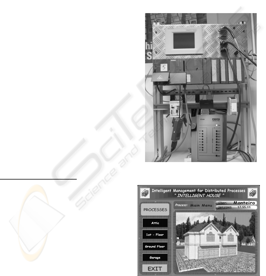
through the FESTO interface SYSLINK (fig. 11).
4.3 Experimental Results
Developed Application Menus:
Several Scada menus had been built. The main
characteristic of a Scada Menu is to be simple,
explicit and quick on transmitting the information to
the system operator. The first Menu developed is a
general overview Menu, named “Main Menu” which
gives us access to the several sections of the
intelligent house and permits the operator to leave
the Scada control and monitoring application (fig.
12). Climbing the tree structure from the main menu
we can reach anyone of the floors that compose the
house. In Fig. 13, the parking place is shown. This
Menu informs about the number of vehicles that
entered or left the park at each gate and the number
of actual free places in the park. Additionally it
shows the state of all sensors and actuators in the
parking place (lights, smoke, gas, water…). From
this Menu we can return to the main Menu, or to
jump into the overview menu.
Specially referring the sensors: lights, water and
gas leakages, the programmed animated images
characterize the binary sensor states by a change of
colour: green indicates the sensor is activated and
red indicates the sensor is inactive.
Concerning the property violation system, this
application developed an alarm that actuates when
the corresponding sensors are actuated (in fig. 13,
sensors s16 and s26 are movement sensors).
Figure 11: Experimental Setup for gate management.
Figure 12: Scada: Main Menu.
TWO LAYER CONTROL STRATEGY APPLIED TO BUILDING AUTOMATION
215
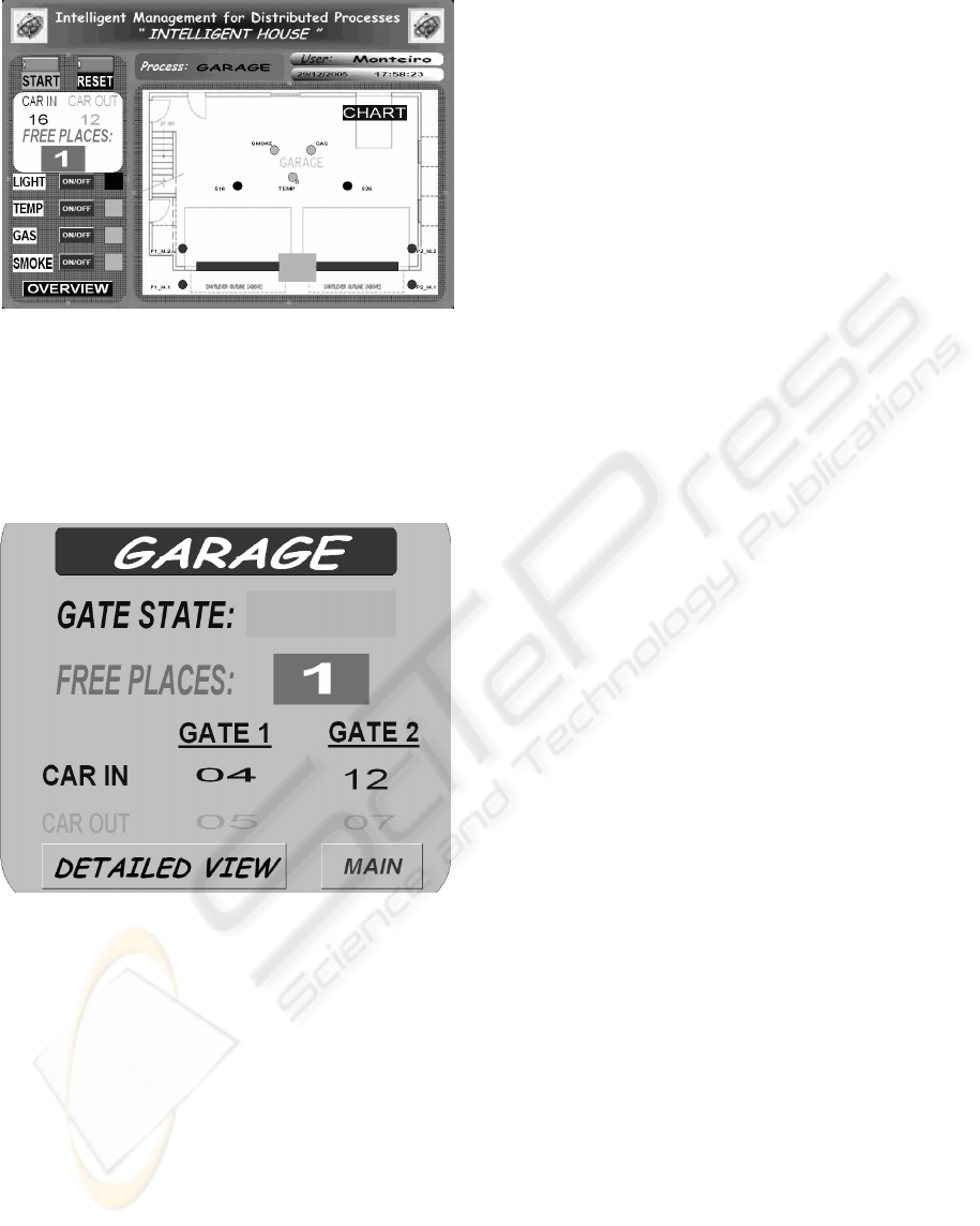
Figure 13: Scada: Parking place menu.
The park overview menu is shown in fig. 14. It
gives the system operator a quick overview over the
parking place capacity (number of cars that entered
or left the park at each gate, actual number of free
places, gates state…)
Figure 14: Scada: Park Overview Menu.
5 CONCLUSIONS
This paper shows the great potential of a control
strategy over two lawyers - distributed local controls
which are connected with an intelligent centralized
control, which has a global view over the system,
and permits an actualization of the local references,
knowing the complete state of the entire system.
The tested prototype worked perfectly showing
the huge potential of communication systems
between distributed processes. These
communication systems allow intelligent centralized
algorithms to manage decision making problems in
real-time environments. The system presented in this
paper combines several technologies (local PLCs,
SCADA systems and network communications) to
reach the goal of efficient management of distributed
processes.
REFERENCES
Christensen, H. (2002). Domestic Robots. Proc. 2002 10
th
IEEE Mediterranean Conf. On Control and
Automation – MED2002, Lisbon, Portugal.
Dey, A., G. Abowd, D. Salber. (1999) A Context-based
Infrastructure for Smart Environments, Managing
Interactions in Smart Environments. Springer-
Verlag, pp. 114-130.
Figueiredo, J., M. Botto. (2005). Automatic Control
Strategies Implemented on a Water Canal Prototype.
Proc. 16
th
IFAC World Congress – Intl. Federation of
Automatic Control, Praha, Czech Republic.
Figueiredo, J., J. M. Sá Costa. (2005). A Two Level
Hierarchical Control Strategy Applied to an Intelligent
House. Proc. IEEE Intl. Symp. On Intelligent Signal
Processing, Faro, Portugal.
Neto, A., J. Martins, S. Zolnier, P. Monteiro, F. Baeta.
(2004). 1-Wire ™ System Performance – An
Application for Temperature Measurement in
Agricultural Buildings. Proc. 2004 6
th
Conf. On
Automatic Control – CONTROLO 2004, Faro,
Portugal, pp. 445-450.
Orr, R., G. Abowd. (2001). The smart Floor: A
Mechanism for Natural User Identification and
Tracking. Proc. 2001 Intl. Conf. On Human Factors in
Computing Systems, Netherlands.
Ratinho, T., J. Figueiredo, M. Rijo. (2002). Modelling,
Control and Field Tests on an Experimental Irrigation
Canal. Proc. 2002 10
th
IEEE Mediterranean Conf. On
Control and Automation – MED2002, Lisbon,
Portugal.
Siemens. (2001). Simatic Net – NCM S7 for Profibus/
FMS. Siemens 12/2001
ICINCO 2006 - ROBOTICS AND AUTOMATION
216
