
DESIGN OF A PROTOTYPE ROBOT VACUUM CLEANER
From Virtual Prototyping to Real Development
Leire Maruri, Ana Martinez-Esnaola, Joseba Landaluze
IKERLAN Research Centre, Arizmendiarrieta 2, E-20500 Arrasate (The Basque Country), Spain
Sergio Casas, Marcos Fernandez
ARTEC Group, Valencia University, E-46980 Paterna, Spain
Keywords: Robot vacuum cleaner, Virtual prototype, Fuzzy logic, SIL (Software-In-the-Loop).
Abstract: This paper presents the prototype of a robot vacuum cleaner designed and constructed by IKERLAN. It
details, above all, the hardware and software components used, as well as the navigation algorithm,
designed using fuzzy logic. In conjunction to this an existing virtual prototype of the robot and the domestic
environment was updated with a view to fine-tuning and testing the real controller of the autonomous robot
by means of SIL (Software-in-the-Loop) simulations. Finally, some of the position estimation problems that
arose in the experimental tests are described.
1 INTRODUCTION
Modern living brings with it the need to use time as
efficiently as possible, one of the key objectives
being to create as much free-time for ourselves as
we possibly can. This explains why people
increasingly surround themselves with appliances
capable of carrying out essential, yet distinctly
unappealing, household chores. It is here that
domestic appliances have a role to play.
Until not so very long ago, a washing machine
and fridge were considered sufficient. However,
when these household appliances, along with the
tumble dryer, hair dryer, microwave, vacuum
cleaner, etc. became commonplace in the home, they
were required not only to perform the task for which
they were designed, but to do so in the simplest and
most efficient way possible. What is more, demand
is increasing with every passing day for new
household appliances capable of making even the
most tedious jobs bearable, such as ironing or
cleaning in general. In an ideal world, the domestic
appliances of today would even be replaced by new
gadgets with ability to perform tasks in a completely
independent way, which is where concepts such as
domotics and domestic robots come in.
One such device is the robot vacuum cleaner, a
very active area of research for several years now,
with many prototypes having been developed, some
of which are now appearing on the market (Irobot,
2006; Electrolux, 2006; Karcher, 2006).
The robot vacuum cleaner is a special case
among mobile robot systems. Taking as a starting
point the principle of a robot capable of navigating
reactively in theoretically unknown environments
and designed to avoid variable obstacles, a number
of different versions of domestic cleaners can be
obtained (ones that vacuum the floor, wash dishes,
polish furniture, etc.) by fitting the requisite
accessories. In order for a robot vacuum cleaner to
take its place among the numerous domestic
appliances on the market today, however, it must
meet some very specific requirements with regard to
price, simplicity, ease of use, independence from the
surrounding environment and cleaning efficiency
among others.
Over the last few years IKERLAN and the
ARTEC Group at the University of Valencia have
been working on the design of a domestic robot,
particularly as an example of the application of HIL
(Hardware-in-the-Loop) technology in the design of
new industrial products. Research was conducted on
the navigation system (sensors, actuators, and
navigation and sweeping algorithms) and tested
using the virtual prototype of a generic robot
vacuum and a domestic environment in HIL
simulation (Fernandez, 2003; Martinez, 2004).
461
Maruri L., Martinez-Esnaola A., Landaluze J., Casas S. and Fernandez M. (2006).
DESIGN OF A PROTOTYPE ROBOT VACUUM CLEANER - From Virtual Prototyping to Real Development.
In Proceedings of the Third International Conference on Informatics in Control, Automation and Robotics, pages 461-468
DOI: 10.5220/0001201004610468
Copyright
c
SciTePress
More recently, a prototype robot vacuum was
designed and constructed. The virtual prototype of
the mobile robot and the domestic environment was
also improved. Among other things, an accurate
model of the vacuum cleaner was added, other
dynamically changing elements were included (such
a ball that appears in the environment) and a version
for Windows/PC was created. As a result, the
control programme designed was fine-tuned and
tested using the virtual prototype, following a SIL
(Software-in-the-Loop) procedure.
This paper presents the most significant aspects
of the robot vacuum cleaner prototype that has been
designed and constructed; its navigation system,
based on fuzzy logic; and the improved version of
the virtual prototype. First of all, the paper briefly
reviews the current situation with regard to research
on robot vacuum cleaners, placing special emphasis
on the designs that are currently available on the
market. It then goes on to describe the hardware and
software contained in the robot vacuum cleaner
designed, as well as the navigation strategy. After
detailing the virtual prototype, the paper concludes
by presenting some of the position estimation
problems that arose in the experimental tests.
2 BRIEF REVIEW OF ROBOT
VACUUM CLEANERS
After years of fits and starts, the market for robot
housemaids finally seems to be taking off. New
models of robot vacuum cleaners are the first signs
that a nascent commercial robot industry is finally
taking hold. However, the robot vacuums now being
sold are not designed to replace the vacuum cleaner
altogether. The manufacturers describe their
products as "maintenance" or "continuous" cleaners
(Kahney, 2003). There are a lot of models of robotic
vacuum cleaners available today, and they range in
price from $50 all the way up to $1,800. These
robots are typically low-slung and compact, meaning
they can get under furniture normally inaccessible to
regular upright vacuum cleaners.
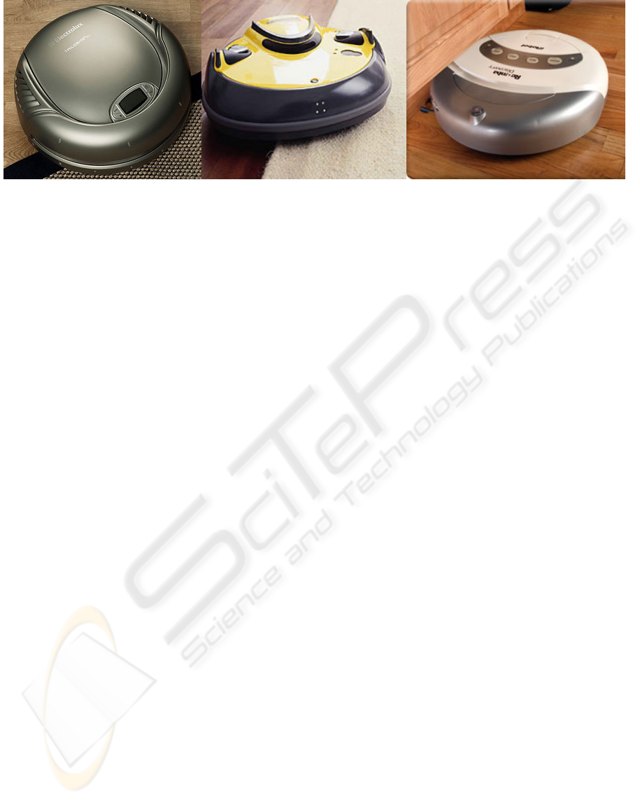
There are three leading robot vacuum companies:
Europe’s Electrolux and Karcher, and the United
States’ iRobot (Figure 1). Other cleaning
manufacturers like Japan’s Hitachi and the UK’s
Dyson are working on the development of this kind
of robot, as are Friendly Robotics, FloorBotics,
Hanool Robotics, Samsung and Lentek.
The most popular robotic vacuum in the United
States is iRobot's Roomba, which comes in various
models ranging from the base-model Roomba Red
($150) to the super high-tech Roomba Scheduler
($350). It is a round-shaped vacuum-device that
works like a pool cleaner, bouncing around a room
until it covers all - or most of - the floor (Kahney,
2003). The cleaning system includes a spinning side
brush that cleans along walls, two counter-rotating
brushes that capture large debris and a vacuum that
picks up dust. At the end of a cleaning cycle or when
the battery is running low, Roomba returns to the
Home Base to recharge. When dirt hits one of the
two sensors located immediately above the brushes,
it turns towards the dirty area, vigorously cleaning
the area most in need of attention. It also includes
infrared sensors that prevent Roomba from falling
off ledges and stairs. The system includes virtual
walls that create an infrared signal that Roomba will
not cross, keeping Roomba where you want it to
clean (Irobot, 2006).
Electrolux's Trilobite is more complex, and more
expensive. The $1800 Trilobite creates an internal
map of the room as it cleans, and recharges
automatically when its power reserves are low. The
type of cleaning programme you want can be
selected (normal, quick or spot) and it has a start
button for immediate cleaning, or alternatively
cleaning times may be set in advance. The Trilobite
sends out harmless ultrasonic signals to spot objects
and avoid them. It begins by edging along the walls
to map the size of the room, whilst simultaneously
cleaning the edges. It then proceeds to clean the
Figure 1: Commercial robot vacuum cleaners: Trilobite, RoboCleaner and Roomba.
ICINCO 2006 - ROBOTICS AND AUTOMATION
462
whole room. A suspension device prevents the
machine from getting stuck, and a special sensor
stops it from falling down stairs (Electrolux, 2006).
Kärcher's RoboCleaner (Karcher, 2006) is
available for about 1100€. It takes a "random-walk"
around the house, sensing walls and obstacles with
its touch-sensitive bumpers. It avoids stairs, and is
low enough to fit under most furniture. A pair of
"rubber ears" on top prevents it from getting stuck.
The RoboCleaner monitors the stream of incoming
dirt and concentrates on especially dirty spots. The
owner need only empty the recharging station's dust
bag when it gets full.
The British company Dyson is trying to develop
a robot cleaner (DC06) and has gone back to the
R&D phase until they can make an affordable,
autonomous vacuum cleaner.
Japanese electronics giant Hitachi is working on
a similar product that also acts as a home security
guard. The robot cleaner can work independently or
manually, controlled by computer or cell phone. An
in-built camera allows the owner to monitor his
house over the Internet while away. It comes with a
charging station, to which it returns to recharge its
batteries and dump its dust load. The robot creates a
map of the house's layout as it moves around. It
remembers the layout of furniture and which areas
of the house have been cleaned and which have not.
It has a retractable 2-inch hose for cleaning in
corners. The machine bristles with sensors (light,
heat and all-around bumpers) for detecting hazards
and preventing it from getting stuck in corners.
3 ROBOT VACUUM CLEANER
DEVELOPED
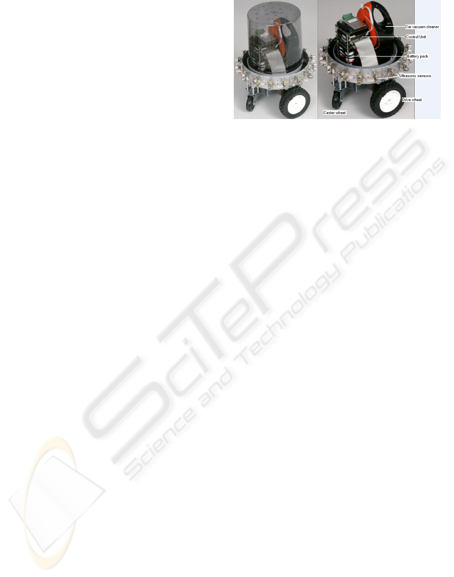
3.1 Hardware Structure
Design and development of the robot vacuum
cleaner prototype was based on off-the-shelf, low-
cost components. The Rex-12 Round Robot Base
with Encoders from Zagros Robotics (2006) was
chosen for the mobile structure and support of all the
components. It consists of a desk base 30 cm in
diameter, which has two drive wheels and is
supported on two casters. The drive wheels are 15
cm in diameter and the two caster wheels 7.5 cm in
diameter. The base includes two 12 V drive motors
for the drive wheels, and each motor has a 500
pulses per revolution HEDS encoder.
The platform can easily carry over 15 kg of
payload at a maximum speed of 24 m per minute.
The sensor system uses 16 units of the SRF08
Ultrasonic Rangefinder Sensor from Robot
Electronics (2006). Communication with the
ultrasonic sensors is via an I2C bus. A BrainStem
GP1.0 Module from Acroname (2006) is used to
read the ultrasonic sensors and measure distances to
obstacles. The distances measured are sent to the
robot controller by means of a RS-232 serial port. In
the prototype a car vacuum cleaner has been used to
suck up dust.
The control unit consists of a sandwich of
PC/104 modules. The modules included are as
follows:
• A CPU board, MOPSIcd7-700 MHz from
Jumptec (2006), with 512 MB of SDRAM and
an IDE compatible Flash-Disk of 96 MB.
• ESC629ER Dual DC Servo Motor Control
Board from RTD (2006) to control the drive
motors of the desk base. It has also 24 TTL
level I/O lines which are used to control the car
vacuum cleaner. A customised circuit was
developed for that purpose.
• PCM-3110 1-Slot PCMCIA Module from
Advantech (2006).
• Instant Wireless Network PC Card from
Linksys (2006) for wireless communications.
• HESC104 Module from Tri-M Engineering
(2006), a DC-to-DC 60 watt converter for
embedded applications that supplies ±5 V and
±12 V.
• BAT104-SLA45 Battery Pack from Tri-M
Engineering (2006). This is sealed, lead acid
battery backup unit for HESC104 power supply.
It consists of 5DD x 4.5A Hr batteries with
digital temperature sensors.
The battery pack and the HESC104 unit supply
the power needed by the drive motors, the car
vacuum cleaner and the control unit itself.
By means of the wireless communication link,
the robot vacuum cleaner programme is loaded and
monitoring data acquired.
Figure 2 shows a photograph of the robot
vacuum cleaner prototype developed, as well as its
main components.
Figure 2: Robot prototype and its components.
DESIGN OF A PROTOTYPE ROBOT VACUUM CLEANER - From Virtual Prototyping to Real Development
463
3.2 Software Structure
The Operating System used in the CPU board of the
mobile robot is eLinOS v2.1, an embedded version
of Linux, with RTAI extension for hard real-time.
The control program is created in a host computer
and then downloaded through the wireless link.
The robot controller has been developed in
Simulink, where it is tested using a simple virtual
environment consisting of a circular or rectangular
room. After ensuring it is operating correctly, the
code of the navigation algorithm only is created
using the RTW (Real Time Workshop) utility. This
code is then integrated into the application along
with the rest of the functionality (reading sensors
and the sending of commands to the motors) and
compiled for eLinOS and Windows. This controller
is embedded in the mobile robot or can be integrated
into the virtual prototype in order to test it.
The controller carries out three basic functions: it
receives information from the sensors on the
distances measured; it periodically calls the
navigation and control algorithm (created with RTW)
to obtain the wheel velocity commands; and it sends
these commands to the motors.
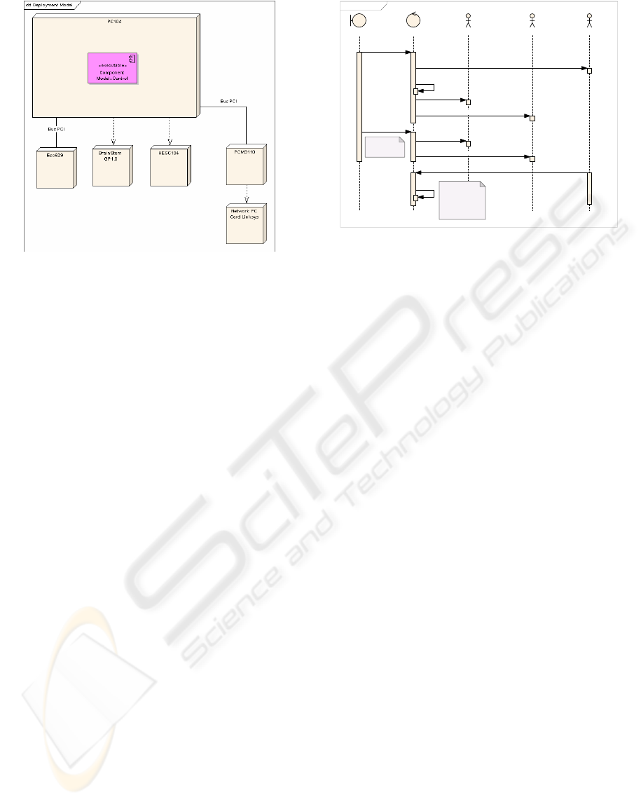
Figure 3 shows the development diagram of the
embedded application, representing the application
as the “Control” component built into the CPU
PC/104, and showing the interaction with the
peripherals fitted on the robot vacuum cleaner.
The application functions as per the sequence
diagram in Figure 4. As soon as it starts up, the
application configures an interruption timer before
starting the input and output (sensors and motors)
and configuring the operating system signals. At the
end of the initialisation process, it enters a loop that
performs two of the basic functions: it reads
information from the sensors and sends the velocity
commands to the motors. In conjunction, the
operating system periodically sends (every 10 ms)
signals via the rigalrm (alarm signal) function.
These signals are captured by the programme and
trigger the call to the “navigate” function, which
implements the navigation control.
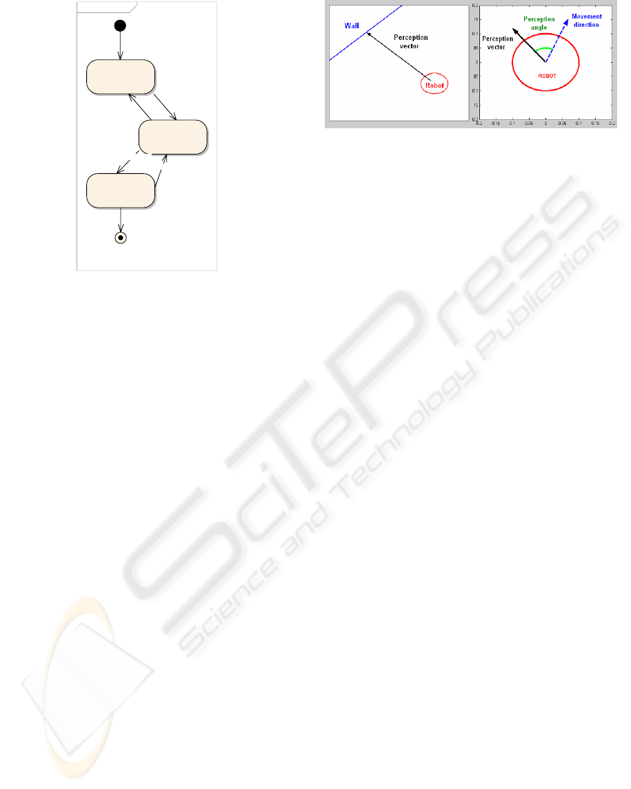
4 NAVIGATION SYSTEM
The navigation system, implemented in
Matlab/Simulink, provides a navigation algorithm
capable of locating a wall in an unknown
environment and following it, as well as determining
when the boundaries of the enclosed area it is
moving in have been defined. It then begins a
sweeping phase in which it covers most of the
enclosed area in an efficient manner. The navigation
system consists, therefore, of three basic stages:
identifying the enclosed area to be swept; the
sweeping of internal areas; and the bordering of
obstacles. Figure 5 shows the statechart diagram of
the navigation application.
In the initial stage the robot performs a square
spiral during which it moves by alternating between
straight lines and right-angle turns until it finds a
wall. At this point it moves to the next stage known
as “wall following”, which, as its name suggests,
involves the robot skirting along walls. Throughout
this phase the robot is controlled by the fuzzy
control system, which attempts to guide it at a fixed
distance from the wall, delimiting the enclosed area
in question (Urzelai, 1997).
Once it has been established that the “wall
following” phase has marked off an enclosed area
(as a result of readings received from the motor
Figure 3: Development diagram of the application.
sd Requirements
Main Con trol TimerMotors
Con trol :
Indefinite Loop
Sensors
Navi gate :
Navi gati on
Algorithm Created
with RTW from
Simulink.
Initialize
Create T imer
Con figure OS
Initialize
Initialize
Control
Rea d
SetReference
Timeout
Navigate
Figure 4: Sequence diagram of the application embedded.
ICINCO 2006 - ROBOTICS AND AUTOMATION
464
encoders), the third and final phase in the
application, known as “sweeping”, is performed.
Here, the algorithm encloses the trajectory taken by
the robot in a cell matrix that enables it to identify
the swept area and, on the basis of this, a decision
strategy informs it of which cells need to be swept at
each point. If at any time an obstacle is detected, the
robot switches back to wall-following status and
adopts a fuzzy control strategy (the same as the one
used in that particular stage).
4.1 Fuzzy Wall-following Control
The “wall following” function features three distinct
modules or parts: pre-processing, fuzzy control and
post-processing.
Pre-processing introduces the concept of the
perception vector (Figure 6). This vector indicates
the proximity of an obstacle and its direction. The
angle of the perception vector is that formed by the
direction the robot advances in. The module of the
vector expresses the distance the robot is from the
wall in a standardised way using an ideal distance
value: 1 if the robot is at the wall, and 0 if it is
double the ideal distance or further. As a result, the
fuzzy control system attempts to keep the module of
the perception vector at 0.5, equivalent to the ideal
distance. The output in this pre-processing block
consists of the module of the perception, the angle of
the perception, the derivative of the perception and
the loss of perception. This last output indicates
whether the robot has switched from measuring
perception to a value of 0 (i.e. when the robot moves
further than it should from the wall).
The navigation module calculates the velocity
commands for the motors. To be able to do this it
features two strategies represented by the first two
stages in the statechart diagram (Figure 5): the first
being a wall-search strategy, and the other a wall-
following strategy designed to identify the sweeping
area. These two control modes are selected
according to the value of the perception vector
module. If the module has a value equal to one, the
control system will search for a wall and will
attempt to follow a square spiral pattern until one is
found, at which point the loss-of-perception signal
resets to zero and the robot attempts to follow the
wall thanks to the wall-following control function
performed by the fuzzy block.
In the search for walls, the square spiral is
generated as a result of two types of commands sent
to the wheels: one in which the robot advances in a
straight line, with the same command being sent to
the two wheels; and the other where the robot rotates
90°, with one wheel receiving a certain velocity
command and the other the same command but with
a different sign, thereby ensuring that the robot
rotates on its axis without lateral displacement.
When the perception value is anything other than
zero (meaning that it has found a wall), the fuzzy
block performs the control. This block has the
“module of the perception” and the absolute value of
the “angle of the perception“ as inputs, thereby
simplifying the fuzzy model, as it is the symmetry of
the problem that is used. The system uses three
fuzzy variables: modP (module of the perception);
angP (angle of the perception); and Giro (the output
variable for the robot’s angle of rotation).
The membership functions of the modP (module
of the perception) input variable appear in Figure 7a.
As stated above, this variable provides an estimate
of the distance to the wall. The membership
functions of the angP (angle of the perception)
variable appear in Figure 7b. As has already been
mentioned, this input is always positive, as it takes
the absolute value, making use of the system’s
symmetry. In the event of this angle being negative,
the sign is changed.
The only output in the block is Giro: the rotation
that the robot must perform to prevent it from
running into, or approaching too close to, the wall,
depending on the value of the module of the
sm Requirements
Initial
Spiral
Wall Follow ing
Sw ee ping
Final
Obstacle
Conto ur Closed
!Wall
Wal l
Figure 5: Statechart diagram of the “navegate” function.
Figure 6: Perception vector and perception angle.
DESIGN OF A PROTOTYPE ROBOT VACUUM CLEANER - From Virtual Prototyping to Real Development
465
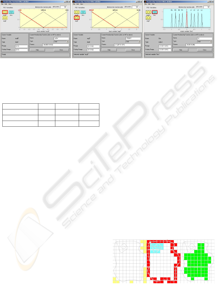
perception. By incorporating the following rules into
the fuzzy controller (Figure 7c), the robot vacuum
cleaner tries to maintain an angle of 90º between the
direction of advance and the wall, being the distance
to the wall the ideal one.
modP/angP
Front Medium Back
Low L1 R2 R4
Medium L3 Z R3
High L4 L2 R1
Having established the rotation the robot must
perform, the post-processing module calculates the
velocity commands to be sent to each of the wheels.
4.2 Sweeping Strategy
Existing robot vacuum cleaners on the market that
have to move around unknown environments mainly
use two navigation strategies. The first involves
random navigation, i.e. the robot moves in a straight
line until it encounters an obstacle and then changes
direction randomly, continuing in a straight line
again until coming across the next obstacle. This
approach, although not particularly efficient, is very
easy to be implemented. The second approach
involves mapping the environment as the robot
moves so that a reference to the robot position can
be obtained and the optimal sweeping strategy
defined. The latter approach was that chosen for the
design of the sweeping algorithm.
Once the contour has been determined, it is
demarcated by a rectangle with as small a surface
area as possible. This area is divided into cells with a
predetermined size. Each cell has a status: the cell
can belong to the contour; the outside of the contour;
or the inside of the contour (Figure 8). As a result,
the input is restricted to the inside of the contour.
From this point on, the behaviour of the
prototype is no longer controlled by fuzzy rules. The
robot proceeds to use the matrix obtained in the first
stage to calculate the points of its next path.
Therefore, some of the cells will change their status
from “inside” to “path”. The cells with the “path”
status are converted into “swept” cells. If the room
were completely empty, the robot would sweep the
room in a spiral.
The process of sweeping inner areas is repeated
continuously until 3% of the area initially selected
for the task is left. At this point, the prototype
detects the zones that are still unswept, known as
"islands". The robot chooses only those “islands”
that are larger than the size of the robot vacuum
cleaner. Then the robot selects the “island” nearest
to its position and approaches it by the shortest
route. Each island then becomes a “small room” to
be cleaned, and sweeping is controlled by the same
rules of behaviour. Once all the islands have been
swept, the robot considers the task completed.
5 VIRTUAL PROTOTYPE OF
ROBOT VACUUM CLEANER
As stated above, one of the main objectives of the
research carried out by IKERLAN and ARTEC was
to validate the use of HIL methodology in designing
and implementing the real prototype. Thus, in order
to provide a realistic environment in which to test
the robot vacuum cleaner, a real-time realistic 3D
simulation was developed alongside the real
prototype. This allowed us to test the HIL strategies
Figure 7: Membership functions of fuzzy variables: a) Perception distance; b) Perception angle; c) Turning angle.
Figure 8: a) Cells outside of the contour; b) Cells on the
spiral and the contour; c) Cells to be swept.
ICINCO 2006 - ROBOTICS AND AUTOMATION
466
by having a better feedback and a visual first
impression of how the control system behaved.
5.1 Description
This virtual prototype is a standalone, real-time,
graphic/dynamic simulation written in C++ that runs
on both Windows and Linux operating systems.
The virtual prototype simulation (hereinafter
referred to as “simulation”) is a multi-threaded real-
time oriented application composed of three main
subsystems (Fernandez, 2003):
• 3D real-time graphic subsystem: an OpenGL
Performer-based module responsible for
providing realism and visual quality to the
application. It takes advantage of the scene-
graph representation of the visual information
while using advanced graphic techniques to
enhance the user’s sense of “immersion”.
• Dynamic simulation subsystem: given the task
of providing the application with realistic
Newtonian physics; based on the Open
Dynamics Engine (ODE).
• Communication subsystem: the module where
the simulation communicates with the control
system in order to get actuator feedback and
provide sensor information.
5.2 Improvements in Relation to the
Existing Prototype
Several changes have been made to the architecture
of the existing prototype (Fernandez, 2003;
Martinez, 2004); the most apparent of which is the
migration to a Windows-based application.
A subtle, yet important, difference with respect
to the existing prototype is that this revised version
of the simulation is able to run independently from
(provided it is supplied with values for the motor
velocities), or alongside, the control system
developed by IKERLAN. This link can be made
with either the hardware prototype or the software
controller that substitutes it, and, as such, HIL
(Hardware-in-the-Loop) becomes SIL (Software-in-
the-Loop).
Little has changed with respect to the existing
version of the graphic subsystem, although new,
more complex 3D models of both the robot vacuum
cleaner and the environment (with a new set of
furniture and home-related items to test the robot
over more challenging conditions than it was done
using the previous prototype) were built.
The dynamic subsystem, nonetheless, has
undergone some dramatic changes in order to adapt
it to the new robot configuration designed by
IKERLAN. This includes some new joints, the
redesign of the locomotion system and a new (and
very necessary) stabilization system. Without this,
the simulation would have not been able to meet the
new time requirements imposed by the increased
complexity of the new graphic models. Likewise,
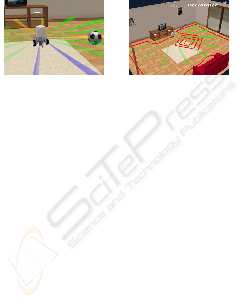
random objects (such as a football, Figure 9a) have
also been introduced into the simulation, in order to
test the ability of the robot to react to unexpected
events and objects which suddenly appear in its path.
Finally, the communication subsystem was also
changed in order to provide a software interface with
the Simulink-based software version of the
controller. This allows us to test the navigation
software directly against the virtual prototype,
instead of having to load it into a hardware platform.
The solution could thus be termed a loophole within
the Software in the Loop.
6 EVALUATION OF RESULTS
The existing virtual prototype described in
(Fernandez, 2003) and (Martinez, 2004) is simpler
and was used to evaluate different sensing
Figure 9: Virtual Prototype: a) General view with a random object; b) Swept area.
DESIGN OF A PROTOTYPE ROBOT VACUUM CLEANER - From Virtual Prototyping to Real Development
467
alternatives and navigation strategies. The
conclusions reached (Martinez, 2004) provided the
starting point for the design and construction of the
real prototype described and presented in this paper.
Once the robot had been designed (Figure 2), the
virtual prototype of the robot and the domestic
environment was updated and enhanced (Figure 9),
as described in section 5. The new virtual prototype
was used to test, above all, the controller in the real
prototype and particularly the navigation and
sweeping strategies. The activation of a trace
mechanism showing the robot’s path, as shown in
Figure 9b, was extremely useful for checking the
effectiveness of the sweeping algorithm.
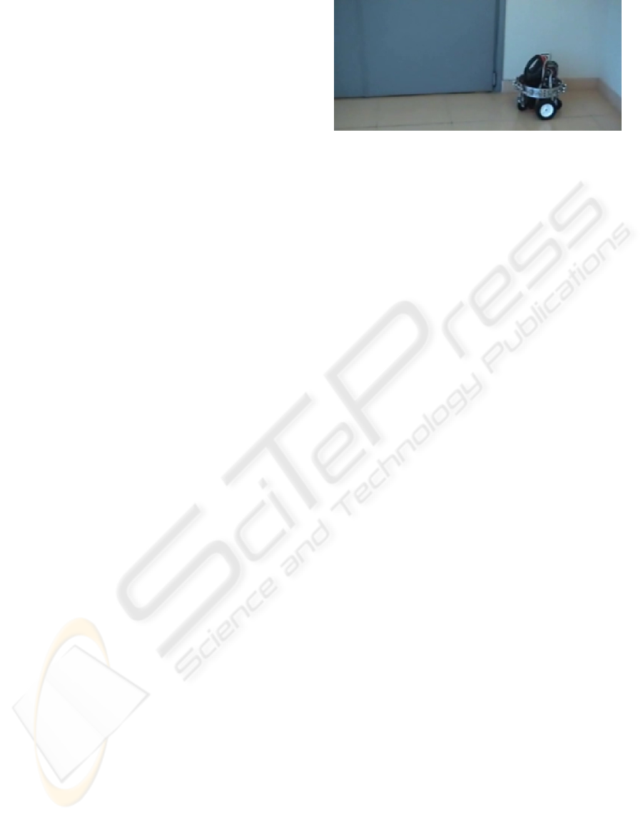
By the end of the process, the real prototype of
the robot vacuum cleaner had been tested
experimentally in simple wall-following and living-
space sweeping tasks. The results for wall following
were positive (Figure 10), although variations were
detected in the estimation of the distance to the wall
whenever the wall material changed (e.g. when the
robot passed in front of a wooden door). By contrast,
the results for the sweeping tasks were worse due to
errors in estimating position using measurements
from the wheel encoders. These errors led to the fact
that the algorithm used for the sweeping of enclosed
areas was inefficient. The main reason for this was
that due to the wheels slipping the measurements
provided by the wheel encoders were inaccurate.
This problem had already been detected in the SIL
simulation with the virtual prototype whenever there
was a change in the surface friction coefficient (e.g.
when the robot moved from a rug onto parquet
flooring, Figure 9b), but was much more serious in
the real prototype.
To draw conclusions from the experimental tests
conducted: the sensing system must be modified or
completed before moving on to a commercial
prototype so that an accurate estimate of the real
position of the robot (the basis of the designed
sweeping algorithm) can be obtained.
7 CONCLUSIONS
This paper presented the prototype of a robot
vacuum cleaner designed and constructed by
IKERLAN. It detailed, above all, the hardware and
software components used, in addition to the
navigation algorithm, the design of which was based
on fuzzy logic. Moreover, an existing virtual
prototype of the robot and its domestic environment
were updated, thereby enabling the fine-tuning and
testing of the real in-built control of the autonomous
robot using SIL (Software-in-the-Loop) simulations.
Finally, the problems arising from the experimental
tests conducted were described in detail, and the
conclusion reached that the sensing system must be
improved so that the real position of the robot,
which forms the basis of the sweeping algorithm
designed, can be estimated accurately.
ACKNOWLEDGEMENTS
The material used in this paper was partly funded by
the Spanish Ministry of Science and Technology and
FEDER (research project DPI2002-04438-C02-01).
REFERENCES
Acroname. 2006. www.acroname.com
Advantech. 2006. www.advantech.com
Electrolux. 2006. http://trilobite.electrolux.co.uk/
Fernandez, M., S. Casas, A. Martinez, L. Nuñez, D.
Guzman, D. Villaverde and J. Landaluze. 2003.
Virtual Prototyping of a Domestic Robot for Design
and Navigation Optimisation. In Industrial Simulation
Conference ISC’2003. 9-11 June, Valencia, Spain.
Irobot. 2006. http://www.irobot.com/home.cfm
Jumptec. 2006. www.jumptec.com
Kahney, L. 2003. Robot Vacs Are in the House. Wired
News. Retrieved January, 2006, from
http://www.wired.com/news/technology/0,1282,59237
,00.html
Karcher. 2006. http://www.robocleaner.de
LinkSys. 2006. www.linksys.com
Martinez, A., L. Nuñez, M. Fernandez, S. Casas and J.
Landaluze. 2004. Virtual Prototyping of a Domestic
Mobile Robot for Design and Navigation
Optimisation. In the International Journal of
Engineering Simulation, ISSN 1468-1137, vol. 5,
number 2, pp. 12-20. July.
Robot Electronics. 2006. www.robot-electronics.co.uk
RTD. 2006. www.rtd.com
Tri-M. 2006. www.tri-m.com
Urzelai, J., J.P. Uribe and J.M. Ezkerra. 1997. Fuzzy
Controller for Wall Following with a Non-
Holonomous Mobile Robot. Fuzzy IEEE.
Zagros Robotics. 2006. www.zagrosrobotics.com
Figure 10: Real Prototype in the wall-following task.
ICINCO 2006 - ROBOTICS AND AUTOMATION
468
