
Analysis of Traffic Agent Scheme for Coverage
Improvement in Wireless Local Area Networks
Hai-Feng Yuan, Yang Yang, Wen-Bing Yao and Yong-Hua Song
School of Engineering and Design
Brunel University, Uxbridge, London, UB8 3PH, United Kingdom
Abstract. Wireless Local Area Network (WLAN) can provide high data-rate
wireless multimedia applications to end users in a limited geographical area and
has been widely deployed in recent years. For indoor WLAN systems, how to
efficiently improve service coverage is a challenging problem. In this paper, we
propose a coverage improvement scheme that can identify suitable Mobile Sta-
tions(MS) in good service zones and use them as Traffic Agents (TA) to relay
traffic for those out-of-coverage MS’s. The service coverage area of WLAN sys-
tem is therefore expanded. Mathematical analysis, verified by computer simula-
tions, shows that the scheme can effectively reduce blocking probability when the
system is lightly loaded.
1 Introduction
In recent years, the proliferation of mobile devices like laptops and Personal Digital
Assistant (PDA) has resulted in the rapid evolution of Wireless Local Area Networks
(WLAN). WLAN can provide high-bandwidth wireless data communications in a lim-
ited geographical area. WLAN is becoming commonly used in offices, residential apart-
ments, hospitals, and other indoor environments. For indoor WLAN systems, signal dis-
persion is highly disturbed. The propagation of radio signals heavily depends on office
dimensions, obstructions, partitioning materials and even the moving objects. There-
fore, how to effectively guarantee the radio signal coverage for complicated indoor
wireless areas is a very challenging problem.
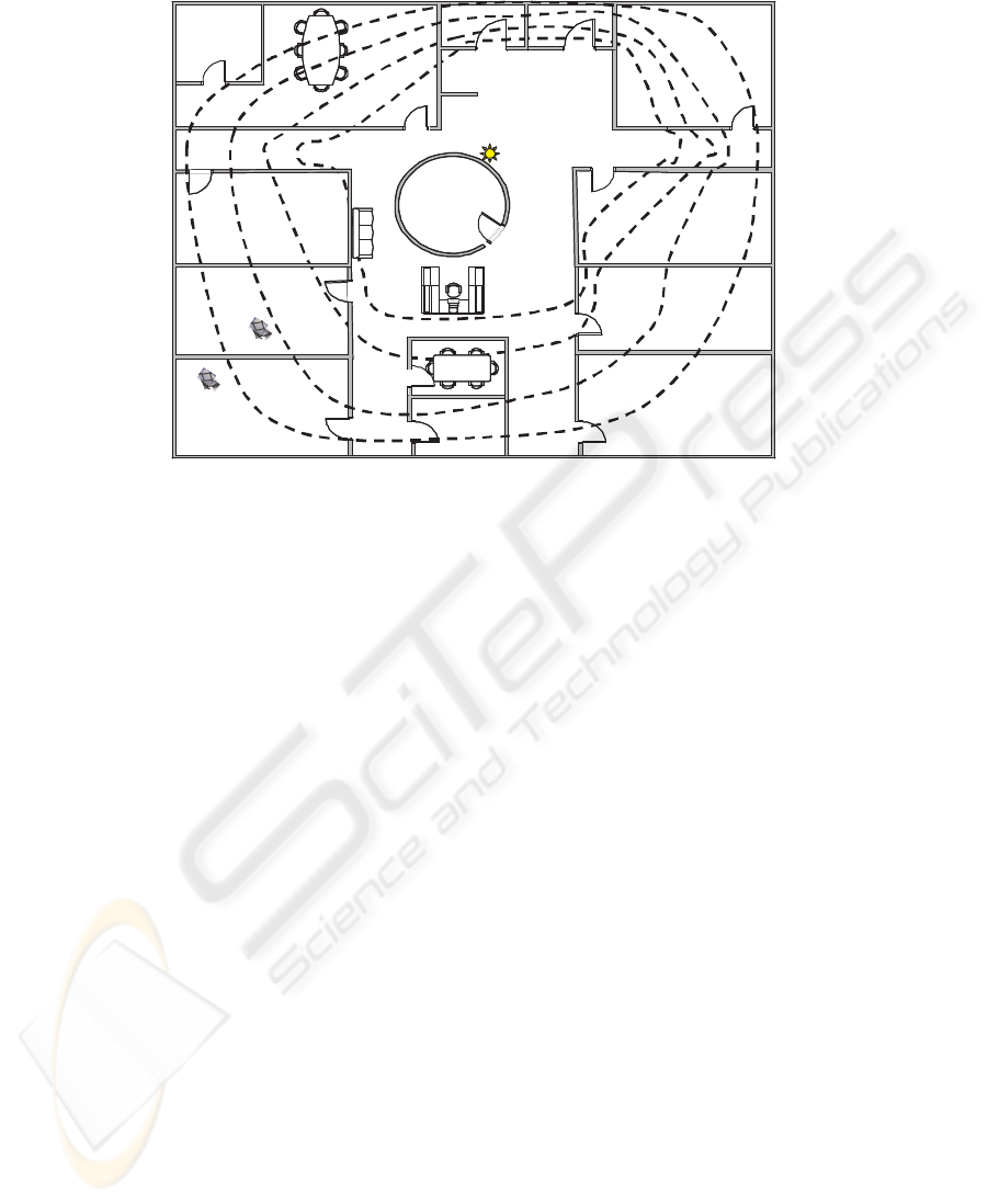
Fig. 1 shows a WLAN deployment example for office area. The Access Point (AP),
usually installed in the ceiling of central area, provides wireless data service for all Mo-
bile Stations (MS) located in its covered area. According to the received signal strength
from the AP, the whole office area can be further divided into five service zones, num-
bered from 0 to 4. Specifically, zone-0 represents the area out-of-coverage so that can-
not support any data services. While zone-1 to zone-4 can support different access data
rates, i.e. 1Mbps, 2Mbps, 5.5Mbps, 11Mbps, as specified in the IEEE 802.11b stan-
dard [1].
The coverage situation of radio signals is almost fixed when the system is deployed.
On the other hand, the required bandwidth from a user or MS is usually application
dependent, not relevant to its location. The coverage problem occurs when a zone-0
MS has a service request. In [5] and [6], the coverage extension schemes using different
Yuan H., Yang Y., Yao W. and Song Y. (2005).
Analysis of Traffic Agent Scheme for Coverage Improvement in Wireless Local Area Networks.
In Proceedings of the 4th International Workshop on Wireless Information Systems, pages 3-12
DOI: 10.5220/0002556900030012
Copyright
c
SciTePress
AP
Zone 0
Zone 1
Zone 2
Zone 3
Zone 4
MS1
11Mbps
5.5Mbps
2Mbps
1Mbps
MS0
Fig.1. A WLAN Deployment Example.
antenna diversity technologies were proposed and studied. To implement these schemes
in real systems, extra hardware devices and more signal-processing power are required.
Other researchers tried to solve the coverage problem by finding the optimal installment
positions for all APs [7–10]. This kind of solutions is, however, highly environment
dependant.
The concept of mixed-mode MS, which can switch between the “infrastructure
mode” and the “ad-hoc mode” dynamically, was presented in [2] to improve system
efficiency and utilization. Based on this concept, a scheme for relieving congested traf-
fic in hot spots is proposed in [3]. Inspired by these work, we propose in this paper the
Traffic Agent (TA) scheme to improve the coverage area of WLAN systems. The TA
scheme uses idle high-zone MS’s to relay traffic from zone-0 MS’s to the AP.
The rest of this paper is organized as follows. In Section 2, the TA scheme is pro-
posed and the complete MS working flow is given. Mathematical analysis of throughput
and blocking performance are derived in Section 3 and Section 4, respectively. In Sec-
tion 5, analytical results, verified by computer simulations, are compared between the
original system and the system using the TA scheme.
2 The Traffic Agent Scheme
On receiving a service request, the MS in zone-0 will switch to “ad-hoc” mode and try
to find an idle MS in high service zones to relay traffic. Take MS0 and MS1 in Fig. 1 as
an example. Suppose MS1 is idle and within the coverage of MS0. Instead of blocking
its service request, MS0 can use MS1 as an agent to relay its traffic to the AP.
4

A “Coverage Improvement Algorithm” will be performed to find TAs, when a zone-
0 MS, say “MS-B”, has a service request. We present in Table 1 and Table 2 the algo-
rithms for the Service-Request MS (i.e. MS-B) and the Traffic Agent MS, respectively.
When the Service-Request algorithm is triggered, MS-B will first switch to the “ad-hoc
mode” and mark the initial frequency channel as No.1 channel. MS-B will then adver-
tise Request-For-Agent (RFA) messages to all the neighboring MS’s within its radio
coverage in all available channels. The RFA message contains MS-B’s identification
and all idle neighboring MS’s can receive the RFA message. As the response, they will
send back positive acknowledgments (ACK) and become candidate TA MS’s (as shown
in Table 2). If two or more ACKs are received, MS-B will select the candidate MS
with the largest zone number (strongest wireless connection with the AP) as its TA
1
.
Next, MS-B will establish connection and exchange data with the selected TA in the
“ad-hoc mode”. The TA will subsequently establish connection and exchange data with
the AP in the “infrastructure mode”. By this two-hop wireless connection, the requested
services from the out-of-coverage zone are accommodated.
Table 1. Service-Request MS Algorithm
if (Receive a service request) then
Switch to “ad-hoc mode”;
Set Channel = 1;
loop
if (Channel N o. > Max Channel ) then
Block service request;
else
Advertise Request-For-Agent message;
if (receive positive response) then
Select an agent & connect;
Transmit data from traffic agent;
end if;
Channel++;
endif
endloop
endif
3 Throughput Analysis
Consider a Basic Service Set (BSS) with one AP and a finite number of MS’s randomly
distributed in five service zones. Under the Distributed Co-ordination Function (DCF)
1
We assume in this study the ad-hoc connection between MS-B and its TA has sufficient band-
width.
5

Table 2. Traffic Agent MS Algorithm
if (MS is idle) then
if (Receive traffic agent request) then
Advertise acknowledge (ACK) message;
if (receive commission) then
Date transmission by TA in “ad-hoc mode”;
end if
end if
else
Data transmission in “infrastructure mode”;
end if
scheme and the ideal channel assumption (i.e. no packet loss, hidden terminal, or cap-
ture effect [11]), the throughput performance for the systems without and with the TA
scheme are analyzed in the following two sections, respectively.
3.1 Throughput without TA Scheme
Let n
i
(0 ≤ i ≤ 4) be the number of zone-i MS’s and let n be the total number of
MS’s. The percentage of zone-i MS’s is therefore given by P
i
= n
i
/n. Let τ be the
probability that a MS has packets to transmit at a specific time slot. The probability P
tr
that at least one transmission occurs at a specific time slot is derived as
P
tr
= 1 − (1 − τ )
n−n
0
. (1)
The success probability P
s
of a transmission period is therefore
P
s
=
(n − n
0
)τ(1 − τ)
(n−n
0
−1)
P
tr
. (2)
Based on the approach given in [12] and [13], system throughput S is derived as
S =
4
i=0
P
s
P
tr
P
i
P
(1 − P
tr
)σ + P
s
P
tr
(
P
R
i
+ SIF S + DIF S + ACK) + P
tr
(1 − P
s
)(
P
R
i
+ DIF S)
,
(3)
where P is average payload length in a packet. Symbol σ denotes the slot size and
R
i
is the channel transmission bit rate in zone-i. SIF S, DIF S and ACK denote
respectively the Short Inter-Frame Spacing, the DCF Inter-Frame Spacing, and the ACK
message transmission time [1].
3.2 Throughput with TA Scheme
Let α
i,j
be the random variable denoting the number of zone-j MS’s that are within the
coverage area of a typical zone-i MS. Given α
i,j
≥ 1, the conditional expected number
6

β
i,j
of the neighboring MS’s is given by
β
i,j
= E[α
i,j
| α
i,j
≥ 1] =
α
i,j
1 − P {α
i,j
= 0}
. (4)
Under the TA scheme, some idle zone-i (1 ≤ i ≤ 4) MS’s are used to relay traffic
for the active zone-0 MS’s, if any. Let η
i
(1 ≤ i ≤ 4) be the active probability of a zone-
i MS, i.e. the probability that a zone-i MS has packets to transmit or relay at a specific
time slot. Recall an MS has probability τ to generate new packets for transmission, so
we get (η
i
− τ) to be probability that a zone-i MS is serving as a TA. For the special
case i = 0, we have η
0
= τ. Given α
i,j
· η
j
≥ 1, the conditional expected number
γ
i,j
of the active neighboring MS’s is derived as
γ
i,j
= E[α
i,j
· η
j
|α
i,j
· η
j
> 1] =
α
i,j
· η
j
1 − (1 − η
i
)
α
i,j
. (5)
The probability (η
4
− τ) that a Zone-4 MS can be used as a TA is given by
η
4
− τ = (1 − η
4
)
γ
4,0
1
1
[1 + (β
0,4
− 1)(1 − η
4
)]
·
1 −
1
1 + (β
0,4
− 1)(1 − η
4
)
γ
4,0
−1
· P
r
{α
4,0
· η
0
≥ 1}
=
(1 − η
4
) ·
α
4,0
· η
0
1 + (β
0,4
− 1)(1 − η
4
)
1 −
1
1 + (β
0,4
− 1)(1 − η
4
)
γ
4,0
−1
.
(6)
An idle zone-3 MS can serve as a TA only when all the zone-4 MS’s are busy. Therefore,
we obtain
η
3
− τ =
(1 − η
3
) ·
α
3,0
· η
0
· η
4
α
0,4
1 + (β
0,3
− 1)(1 − η
3
)
1 −
1
1 + (β
0,3
− 1)(1 − η
3
)
γ
3,0
−1
.
(7)
Similar, we get
η
2
− τ =
(1 − η
2
) ·
α
2,0
· η
0
· η
4
α
0,4
· η
3
α
0,3
1 + (β
0,2
− 1)(1 − η
2
)
1 −
1
1 + (β
0,2
− 1)(1 − η
2
)
γ
2,0
−1
,
(8)
and
η
1
− τ =
(1 − η
1
) ·
α
1,0
· η
0
· η
4
α
0,4
· η
3
α
0,3
· η
2
α
0,2
1 + (β
0,1
− 1)(1 − η
1
)
1 −
1
1 + (β
0,1
− 1)(1 − η
1
)
γ
1,0
−1
.
(9)
The probability P
′
tr
that at least one transmission occurs at a specific time slot is
given by
P
′
tr
= 1 −
4
Y
i=1
(1 − η
i
)
n
i
. (10)
7

The success probability P
s,i
of a transmission or relay period for a zone-i MS is given
by
P
s,i
=
n
i
η
i
(1 − η
i
)
n
i
−1
4
Y
j=1,j6=i
(1 − η
j
)
n
j
P
′
tr
, 1 ≤ i ≤ 4 . (11)
The total success probability P
′
s
is the summation of P
s,i
, i.e.
P
′
s
=
4
X
i=1
n
i
η
i
(1 − η
i
)
n
i
−1
4
Y
j=1,j6=i
(1 − η
j
)
n
j
P
′
tr
. (12)
Finally, system throughput under the TA scheme is derived to be
S
′
=
4
i=1
P
′
s
P
′
tr
P
i
P
(1 − P
′
tr
)σ + P
′
s
P
′
tr
(
P
R
i
+ SIF S + DIF S + ACK) + P
′
tr
(1 − P
′
s
)(
P
R
i
+ DIF S)
.
(13)
4 Blocking Probability
When the TA scheme is not used, all zone-0 MS’s cannot get access to the AP so
that their service requests will be blocked. The corresponding blocking probability is
P
b,0
= 1. For the MS’s in other zones, they have the same blocking probability
P
b,i
= 1 − (1 − τ )
n−n
0
−1
, 1 ≤ i ≤ 4 . (14)
The overall blocking probability P
b
is simply the weighted summation of P
b,i
, i.e.
P
b
=
4
X
i=0
P
i
· P
b,i
= P
0
+
1 − (1 − τ)
n−n
0
−1
· (1 − P
0
) .
(15)
When the TA scheme is used, the average total number of service requests generated
by all-zone MS’s is kept unchanged, i.e.
P
4
j=0
n
j
· τ. The percentage P
′
0
of the zone-0
requests that cannot identify any TAs is derived as
P
′
0
=
n
0
· η
0
−
P
4
i=1
n
i
· (η
i
− τ) · (1 − η
i
)
n
i
−1
Q
4
j=1,j6=i
(1 − η
j
)
n
j
P
4
j=0
n
j
· τ
. (16)
So the corresponding blocking probability is P
′
b,0
= 1. The percentage P
′
i
(1 ≤ i ≤ 4)
of the new and relay transmissions from the zone-i MS’s is
P
′
i
=
n
i
· η
i
P
4
j=0
n
j
· τ
, 1 ≤ i ≤ 4 . (17)
8
The corresponding blocking probability P
′
b,i
for the MS’s in zone-1 to zone-4 is given
by
P
′
b,i
= 1 − (1 − η
i
)
n
i
−1
4
Y
j=1,j6=i
(1 − η
j
)
n
j
, 1 ≤ i ≤ 4 . (18)
The overall blocking probability for the systems using the TA scheme is therefore
P
′
b
=
4
X
i=0
P
′
i
· P
′
b,i
= P
′
0
+
4
X
i=1
1 − (1 − η
i
)
n
i
−1
4
Y
j=1,j6=i
(1 − η
j
)
n
j
· P
′
i
.
(19)
5 Analytical and Simulation Results
The system parameters for deriving the numerical and simulation results are summa-
rized in Table 3. In addition, we assume the random variables α
i,j
(0 ≤ i, j ≤ 4) have
the same uniform distribution in the range [0, 4]. So, we obtain
α
i,j
= 2 and β
i,j
= 2.5.
Table 3. System Parameters
R
i
(1, 2, 5.5, 11) × 10
6
bps, i = 1, 2, 3, 4.
n 40
P 1024 bytes
P
i
0.2, 0.2, 0.2, 0.2, 0.2, i = 0, 1, 2, 3, 4.
SIF S 10µs
DIF S 50µs
ACK 19.2µs
σ 20µs
Fig. 2 shows the system throughput as a function of the probability τ that a new
service request is generated by an MS in each time slot. The analytical results shown in
solid lines are perfectly verified by the simulation results in markers. As seen, although
the TA scheme increases the active probability of in-coverage MS’s from τ to η
i
(1 ≤
i ≤ 4) and decreases the success probability of a busy period from P
s
in (2) to P
′
s
in
(12), it can still offer the same maximum throughput performance as the system without
using the TA scheme. Specifically, when the system is lightly loaded, say τ ≤ 0.005, the
9
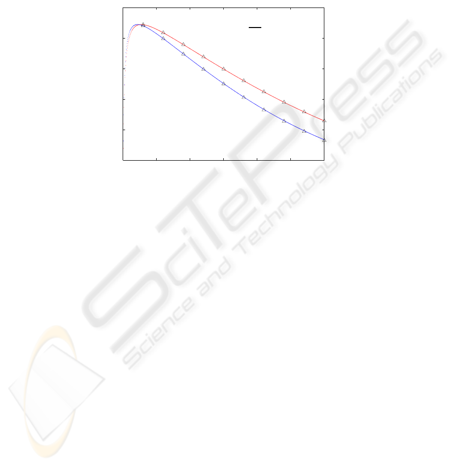
use of TA scheme can slightly improve the system throughput because a small amount
of zone-0 traffic is relayed to the AP through some two-hop connections. When the
probability τ becomes large, most MS’s are busy and cannot serve as TA. In addition,
due to more frequent packet collisions, the success probability of a busy period becomes
smaller and the throughput curve under the TA scheme is lower.
0 0.01 0.02 0.03 0.04 0.05 0.06
0.5
1
1.5
2
2.5
3
x 10
6
New Request Generation Probability
System Throughput (kbps)
With TA scheme
Without TA scheme
∆ ∆ ∆ Simulation Results
Analytical Results
Fig.2. System throughput.
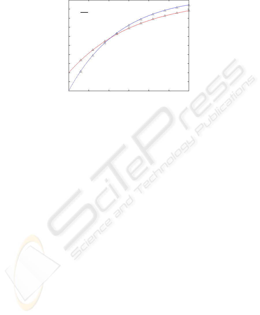
Fig. 3 shows the overall blocking probability as a function of τ . As expected, the
TA scheme can offer much better blocking performance when the system is lightly
loaded. In this case, the TA scheme can accommodate most zone-0 service requests
by identifying suitable TAs to relay their traffic to the AP. When τ is large, few in-
coverage MS’s are suitable for serving the zone-0 MS’s as TAs. If any, they will further
increase the active probability of in-coverage MS’s and incur more collisions in packet
transmission. The resulting overall blocking probability, calculated by (19), is therefore
larger than that of the system without using the TA scheme.
6 Conclusions
For indoor WLAN systems, how to efficiently improve service coverage is a challenging
problem. The Traffic Agent scheme proposed in this paper can identify suitable MS’s in
good service zones as agents to relay traffic for those out-of-coverage MS’s. Analytical
results, verified by simulation results, show that the TA scheme can reduce the system
blocking probability by establishing the two-hop traffic connections between the out-
of-coverage MS’s and the AP when the system is lightly loaded. The service coverage
of indoor WLAN systems is therefore enhanced.
10
0 0.01 0.02 0.03 0.04 0.05 0.06
0
0.1
0.2
0.3
0.4
0.5
0.6
0.7
0.8
0.9
1
New Request Generation Probability
Blocking Probability
Without TA scheme
With TA scheme
Analytical Results
∆ ∆ ∆ Simulation Results
Fig.3. Overall blocking probability.
References
1. IEEE Standards Board, “Wireless LAN Medium Access Control (MAC) and Physical Layer
(PHY) specifications,” IEEE Std 802.11-1997, Nov.1997.
2. J. C. Chen, S. H. Chan, J. Y. He, and S. C. Liew, “Mixed-mode WLAN: the integration of ad
hoc mode with wireless LAN infrastructure,” in Proceedings of IEEE Globecom’03, vol. 1,
pp. 231-235, Dec. 2003.
3. J. C. Chen, J. Y. He, and S. H. Chan, “Relieving wireless hot-spot congestion through ad hoc
connections,” in Proceedings of the Fifth International Conference on Mobile and Wireless
Communications Networks (MWCN’03), Oct. 2003.
4. R. S. Chang, W. Y. Chen, and Y. F. Wen, “Hybrid wireless network protocols,” IEEE Trans-
actions on Vehicular Technology, vol. 52, no. 4, pp. 1099-1109, Oct. 2003.
5. A. Lackpour, “Maximizing wireless LAN range by exploiting two types of antenna diver-
sity,” Oberon Wireless Inc., Jan. 2004.
6. H. R. Chuang, L. C. Kuo, C. C. Lin, and W. T. Chen, “A 2.4 GHz polarization-diversity
planar printed antenna for WLAN and wireless communication systems,” in Proceedings of
IEEE Antennas and Propagation Society International Symposium, vol. 4, pp. 76-79, Jun.
2002.
7. A. Hills, J. Schlegel, and B. Jenkins, “Estimating signal strengths in the design of an indoor
wireless network,” IEEE Transactions on Wireless Communications, vol. 3, no. 1, pp. 17-19,
Jan. 2004.
8. Y. Lee, K. Kim, and Y. Choi, “Optimization of AP placement and channel assignment in
wireless LANs,” in Proceedings of IEEE Conference on Local Computer Networks, pp. 831-
836, Nov. 2002.
9. R. H. Wu, Y. H. Lee, and S. A. Chen, “Planning system for indoor wireless network,” IEEE
Transactions on Consumer Electronics, vol. 47, no. 1, pp. 73-79, Feb. 2001.
10. L. Nagy and L. Farkas, “Indoor base station location optimization using genetic algorithms,”
in Proceedings of IEEE International Symposium on Personal, Indoor and Mobile Radio
Communications (PIMRC’00), vol. 2, pp. 843-846, Sept. 2000.
11

11. K. C. Huang and K. C. Chen, “Interference analysis of nonpersistent CSMA with hidden
terminals in multicell wireless data networks,” in Proceedings of IEEE International Sympo-
sium on Personal, Indoor and Mobile Radio Communications (PIMRC’95), vol. 2, pp. 907 -
911, Sept. 1995.
12. G. Bianchi, “Performance analysis of the IEEE 802.11 distributed coordination function”
IEEE Journal on Selected Areas in Communications, vol.18, no.3, pp. 535-47, Mar 2000.
13. Z. H. Velkov and B. Spasenovski, “Saturation throughput - delay analysis of IEEE 802.11
DCF in fading channel,” in Proceedings of IEEE International Conference on Communica-
tions (ICC’03), vol.1, pp.121-126, May 2003.
14. J. C. Stein, “Indoor radio WLAN performance part II: range performance
in a dense office environment,” Intersil Corporation Technical Report,
http://wifi.erasme.org/IMG/experience
attenuation.pdf
15. J. Gomez, A. T. Campbell, M. Naghshineh, and C. Bisdikian, “PARO: supporting dynamic
power controlled routing in wireless ad hoc networks,” Kluwer Wireless Networks, no. 9, pp.
443-460, Sept. 2003.
16. N. B. Salem, L. Buttyn, J. P. Hubaux, and M. Jakobsson. “A charging and rewarding scheme
for packet forwarding in multi-hop cellular networks,” in Proceedings of ACM International
Symposium on Mobile Ad Hoc Networking and Computing (MobiHoc’03), pp. 13-24, Jun.
2003.
17. R. Dube, C. D. Rais, S. K. Tripathi, and K.Y. Wang, “Signal stability based adaptive routing
(SSA) for ad hoc mobile networks,” IEEE Personal Communications, vol. 4, pp. 36-45, Feb.
1997.
12
