
MODEL SHARING IN THE SIMULATION AND CONTROL OF
DISTRIBUTED DISCRETE-EVENT SYSTEMS
Fernando Gonzalez
Department of Electrical and Computer Engineering
University of Central Florida, Orlando, Florida 32816
Keywords: Discrete Event Systems, Modeling, Simulation, Control, Distributed Systems
Abstract: Today, sophisticated discrete-
event systems are being designed whose complexity necessitates the
employment of distributed planning and control. While using a distributed control architecture results in the
overall system model consisting of a collection of independent models, today's commercially available
simulation languages can only accommodate a single model. As a result, in order to use these simulation
languages one must create a new system model that consists of a single model but yet models a collection of
models. Typically the communication among the distributed models is ignored causing inaccurate results.
In this paper we use our simulation concept, also presented in this paper, to create a simulation tool that
enables the simulation of distributed systems by using a collection of models rather than a single model.
With our concept we create a methodology that accomplishes this by simulating the communications among
the distributed models. Besides the benefit of not having to create a new model for simulation, this
methodology produces an increase in accuracy since the communication among the models is taken into
consideration. Furthermore this tool has the capability to control the system using the same collection of
models.
1 INTRODUCTION
Flexible manufacturing systems represent an
interesting control problem because they generally
have its control architecture distributed among many
different computers. While creating a controller for
each subsystem is not difficult, coordinating the
individual controller to perform a common task may
be more challenging. Manufacturing systems are
typically modeled using discrete-events. And
discrete-event simulation is commonly used to
evaluate possible alternative actions used in decision
making. This leads to a modeling problem. Since the
controller of the plant is distributed, that is it
consists of many controllers running independently,
and the simulation model must not be distributed
how is one to model a system using a single model
when the actual controller consists of a collection of
models? Currently the solution is to create a new
model that captures the control logic of the complete
controller system. This of course requires writing a
new model that hopefully captures this true control
logic correctly including all of the communication
among the controllers. In addition to representing a
significant modeling effort, it leads to a source of
error. This is especially true when you consider
modeling the communication. In this paper we
present a modeling approach that has the capability
of accepting a collection of models. We can use the
models that are used for control directly by simply
including them into the simulation. Not only can our
simulation handle the collection of models but it also
automatically models the communication among the
controllers. This paper is based on the simulation
and control of distributed large complex systems
whose behavior is characterized by discrete events
such as a flexible manufacturing system, FMS. FMS
produce many part types concurrently in very small
quantities. These systems are difficult to control
because they generally operate in a highly transient
state.
The following research efforts are related to our
work. (Peters
et al. 1996), (Smith et al. 1994) and
(Smith and Peters 1998) have adapted Arena
(Kelton, Sadowski and Sadowski 2001) to control
their experimental FMS. However, unlike the
modeling approach to be discussed in this paper,
their control architecture uses one hierarchical level
where a single supervisor, the cell controller,
144
Gonzalez F. (2005).
MODEL SHARING IN THE SIMULATION AND CONTROL OF DISTRIBUTED DISCRETE-EVENT SYSTEMS.
In Proceedings of the Seventh International Conference on Enterprise Information Systems, pages 144-151
DOI: 10.5220/0002549401440151
Copyright
c
SciTePress
manages a set of subordinate processes. In their
modification of Arena, they have included special
events in order to facilitate message passing among
the controllers. Furthermore, to model a complex
FMS or other multi-level, distributed system, the set
of modeling elements provided by ARENA, as well
as most simulation languages, severely constrains
the modeling process. This is particularly true when
one attempts to assess the impact of the control
architecture upon the system. (Davis et al. 1993) and
(Davis 1998) details the numerous restrictions that
current simulation languages impose upon the
modeling of hierarchically distributed systems.
(Mize et al. 1992) further discusses the inaccuracies
that ensue from using current simulation languages
in order to model an FMS.
(Narayanan et al. 1992), (Govindaraj et al.
1993) and (Bodner and Reveliotis 1997) have also
developed simulation tools that are capable of
controlling a system. They claim that the typical
approach to address the complexity of FMS control
systems is a hierarchical decomposition. A widely
used decomposition features tree layers, Strategic
Decisions, Tactical Decisions and Operational
Decisions, (Arango and Prieto-Diaz 1991) and
(Stecke 1985). In (Bodner and Reveliotis 1997),
(Govindaraj et al. 1993), and (Narayanan et al.
1992), they claim that to handle lower level issues
involving the real-time control, two additional layers
are needed. The Structural and Equipment Control
layers address issues such as deadlock avoidance. In
these papers, hierarchical decomposition refers to
the logical decomposition of the decision making
process while we refer to it as the actual
decomposition of the controller that yields a
distributed controller. Incidentally they also claim
that FMS exist but there are no controllers for them.
The notions of multi-resolutional architectures
and task decomposition have been discussed by
many. The interested reader is referred to (Albus and
Meystel 1995 and 1997) for a discussion of these
terms. In the same reference, these authors discuss
their reference architecture for distributed intelligent
control and the associated real-time control system
for its implementation. The major distinction
between their architecture and ours, discussed
below, is that they have separated the planning and
control functions within a given controller. Our
approach does not separate these functions.
Secondly, we make heaver use of on-line simulation.
2 THE DISTRIBUTED MODELING
METHODOLOGY
This methodology presents a very novel approach to
simulating distributed systems using a single thread.
It is assumed that the control architecture is
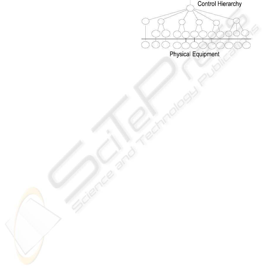
hierarchical. Figure 1 shows a typical control
architecture for an example system.
Figure 1: The hierarchical architecture used in our
physical model
This methodology is based upon the belief that
the interactions among the controllers must be
considered by the simulation model in order to
accurately model a system with a distributed control
architecture. The single most important
characteristic of the methodology and what separates
it from other object-oriented simulation approaches
is its attention to modeling the flow of messages
among the controllers included within the
architecture. By modeling the flow of messages, the
methodology allows the simulation to accommodate
any number of models. Recall that the controller is
distributed. That means that there are many
independent controllers each running with its own
model. This methodology allows us to simulate the
complete system using the models from the
controllers (Gonzalez 2004). This has many
advantages:
1. The simulation is more accurate since it includes
all of the communication among the distributed
controllers. This was the original motivation for
developing our methodology.
2. The simulation produces maximum fidelity since
the same models are used for both simulation and
control. Model verification is a major effort in
modeling usually requiring more effort then to
actually build the model. Furthermore there is
always the risk that the model does not represent
the control logic correctly. Using our method
reduces the chances of discrepancies between the
models used for simulation and those used for
control. This simplifies the verification phase of
MODEL SHARING IN THE SIMULATION AND CONTROL OF DISTRIBUTED DISCRETE-EVENT SYSTEMS
145
modeling and produces a model that represents
the true logic.
3. The modeling effort is shared between control
and simulation. They both share the same models
so only one set is made. In fact without our
methodology many more models will have to be
created. Since each controller has a different set
of subordinate controllers in its control domain,
each one will need a different model. Only the
model in the very bottom row will be able to use
there exiting models. Each model will need to
include its own logic as well as the logic of all of
its subordinate controllers.
4. The control and simulation models necessarily
employ the same state definition since they are in
fact the same code. This simplifies the task of
initializing the simulation model to the current
system-state. If the simulation and control
models employ different state definitions, which
is the case when one employs conventional
simulation approaches, then one must translate
the measured system variables into values for the
state variable employed within the simulation
model. This is a relatively large effort (Gonzalez
and Davis 1998a).
5. This methodology offers multiresolutional
modeling for simulation. Since the system
models have a hierarchical organization, the
simulation resolution can be dynamically
selected by selecting the levels in the hierarchy
to include models for. For example, in Figure 1,
if the top most controller wants to make a fast
but rough decision it may only include the next
level down. This increases the simulation speed
at a cost of accuracy. Furthermore if a controller
on the 2nd level wants to make a decision it will
only include the 3 controllers below it since the
others have no relevance to its decision. Since
the models are independent, to vary the
resolution we simply include the desired models
with no extra modeling effort required.
3 THE SIMULATION AND
CONTROL TOOL
In order to use the control models in the simulation
directly a tool needs to be used that can run in
control and simulation mode, in this way the same
model, written for the same tool, can be used for
both control and simulation. The state definition can
then be simply the contents of the model’s variables
without any need for interpreting the information in
these variables. We have developed a tool based on
this methodology. This tool is described in more
detail in (Gonzalez and Davis 2003). The goal for
developing this software tool is to provide a
simulation approach using C++ that provides the
modeling convenience of a conventional simulation
language while providing the additional modeling
capabilities that are needed to control a real-world
system, particularly hierarchically distributed
systems. A set of C++ objects was developed in
order to provide the basic necessary modeling
elements that are employed in nearly all simulation
and control scenarios, irrespective of which
modeling methodology is being employed.
In this tool each included modeling element is
represented as an object in C++. As with most
simulation approaches, the adopted simulation
approach is event-driven, and an executive object
manages the sequential processing of events. Two
event lists (discussed below) are maintained where
the events are stored as they wait to be executed at
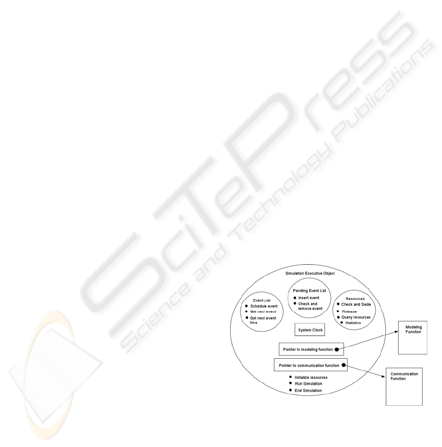
the proper simulated time. The simulation object,
Figure 2, is a C++ object that contains the scheduled
event list, pending event list, list of resources, the
executive function, a pointer to the system model,
and the communication object that interacts with the
hardware. The executive function manages the
chronologically ordered scheduled event list and the
pending event list. It manages the processing of the
events as they are removed from the event lists,
schedules new events that are to be placed into either
the scheduled or pending event list, and manages the
allocation of resources. After each event is
processed, the simulation object removes the next
event with the smallest event time from the event list
and then invokes the proper object to manage the
event’s execution.
Figure 2: The Executive Object.
Using a streamlined approach, there are two
basic types of events that can occur. The
QUESEIZE event occurs when resources become
available for assignment to a requesting entity. The
ICEIS 2005 - INFORMATION SYSTEMS ANALYSIS AND SPECIFICATION
146

DELAY event occurs whenever a delay is
completed. There are also other types of events that
provide capability for control but which are not
considered in most simulation tools, including the
PENDING, TIMEOUT, and ERROR events.
In order to run, the system model must be
attached to the simulation object. A communication
function must also be provided to the simulation
object in order to permit this object to communicate
with the hardware when the model is running in a
control mode. This function handles all of the
communications among the distributed controllers
and the various machines.
The simulation object can operate in the
following two modes:
Simulation mode: In this mode, the system clock
advances in discrete increments. Every time an
event is pulled off the event list, the time is
incremented to the event’s time of occurrence.
No hardware is present. The model executes
purely as a software program.
Control mode: In control mode, the system clock
runs in real time. That is, the system clock is a
conventional clock, like the one on the wall,
where time advances continuously. The events
are pulled off the event list when their event time
occurs. Hardware may be present. The pending
event list is used to allow the executive function
to determine when events occur.
4 DISTRIBUTED MODELING
In order to build the complete simulation model, one
simply includes all of the simulation objects into a
single program along with the coordination object.
The coordination function within the coordination
object coordinates the execution of all of the
simulation objects. It also has the global event list
and the message relay discussed later. When the
distributed model is executed upon a single
computer, only one of the simulation objects can be
executed at a given time because there is only one
computational thread. In order to emulate all of the
simulation objects operating concurrently on a single
processor, the coordination function executes one
simulation object for a short time and then switches
to another object. The coordination function uses its
global event list and its message relay to determine
which simulation object to execute next. The
individual simulation objects return control back to
the coordination function when it is done executing
all of the events that occur during that instance of
time. Note that in simulation, the time it takes the
computer to execute the segment of event code that
handles is usually neglected, and an event can be
assumed to occur in an instance of time.
Furthermore, if an event triggers the immediate
execution of another event, then this second event is
assumed to occur at the same instant of time. This is
why the coordinating function has the liberty to give
control to an individual simulation object for the
duration that it takes that object to execute an event
while meeting the stated objective of emulating
concurrent operation.
In a nondistributed simulation of the system, the
executive function constantly cycles in a loop. This
loop starts by checking the event list for the next
event. It then executes this event. After executing
the event, it checks to see whether there are any new
events resulting from the execution of this event. An
event may cause a second event to execute by the
releasing of resources. Thus, the execution of an
event may cause a chain reaction. All the events in
this chain are executed within this single executive
function cycle. In control mode, at the end of the
current cycle, the executive function checks to see
whether any message has arrived from the
communication pipelines. If a message has arrived,
the pending event list is then checked to find the
proper event to be executed. In either mode, the
executive function then initiates a new event-
processing cycle.
In order to permit several executive objects to
operate concurrently while in the control mode, the
executive function is modified so that it cycles
through the loop only once every time it is called.
Furthermore, it does not check the communication
pipelines at the end of the cycle. All the
communication is handled by a message relay
contained within the primary executive function.
The executive function is responsible for calling the
executive function of the model that will execute the
next event. At this time, the submodel’s executive
function cycles through the event-processing loop
once and then returns program control back to the
coordinating function. This method of sharing the
computing processor operates on a similar principle
as many multi-tasking operating systems.
Another special feature of our simulation tool is
the manner by which messages enter the model.
Instead of checking the communication lines every
time the executive function reaches the end of an
event processing cycle, the lines are not checked at
all. Rather, the coordination function manages the
flow of messages. Whenever a message is present,
the coordination function calls the executive
function of the appropriate submodel’s object and
provides it with the message. The executive function
of that object then handles the message by executing
the proper events in the same way that it previously
MODEL SHARING IN THE SIMULATION AND CONTROL OF DISTRIBUTED DISCRETE-EVENT SYSTEMS
147
handled a message when it was responsible for
detecting the message arrival. We adopted this
approach to insure that a single entity, namely the
coordination function, was responsible for
monitoring the arrival of all messages.
The last feature in our simulation software is the
DELAY modeling element. When a DELAY
element is executed, in addition to scheduling a
DELAY event onto the submodel’s scheduled event
list, it also automatically schedules a DELAY event
into the coordination object’s global event list as
well. Using this approach, the coordination function
maintains a chronologically ordered, global event
list with all of the events associated with every
simulation object. The coordination function uses
this global event list to determine which simulation
object will be invoked next. Since the scheduling of
events into this global event list occurs
automatically, the user does not need to consider this
global event list when modeling a local delay. From
the user’s point of view, the delay is modeled in the
same way as if the model were not a member of a
collection of distributed simulation objects. As a
matter of fact, no part of the submodel has to be
modified to accommodate the distributed simulation.
Each submodel executes as though it is running on
its own dedicated computational thread. This is
important because it allows the modeling engineer to
implement a distributed model the same manner as
when the model was not distributed. Again this
feature is essential because the model will be used
both to project the response and to control the
system.
5 THE COORDINATION
FUNCTION
The coordination function is a supervisory function
that manages the execution of all of the submodels’
simulation objects. The coordination object contains
a global event list and a message relay. This
function runs in a cycle much the same way the
simulation objects do when running independently
(not as part of a distributed simulation). In the
typical simulation mode, the event-processing cycle
starts by removing the next event from the global
event list and passing it to the appropriate submodel
for execution. While a submodel is being executed,
the message relay, which acts as the network,
receives all of the messages that are generated by the
submodel that is currently executing. These
messages are stored in the rear of the message queue
within the message relay, which is used to model the
network. Once the submodel finishes executing its
current event-processing cycle, the coordination
function removes the first message from the front of
the message queue and passes it to the recipient
submodel. The submodel then receives the message
and executes the appropriate functions that are
needed to handle the message. Additional messages
may again be generated and are inserted at the rear
of the message queue. Once control is returned to
the coordination function, it removes the next
message from the front of the message queue and
recycles it though the message-processing loop.
This procedure is repeated until no messages remain
in the message queue. At this time the coordination
executive function finishes its cycle and begins the
next cycle by removing the next event in the global
event list and passing it to the appropriate simulation
object.
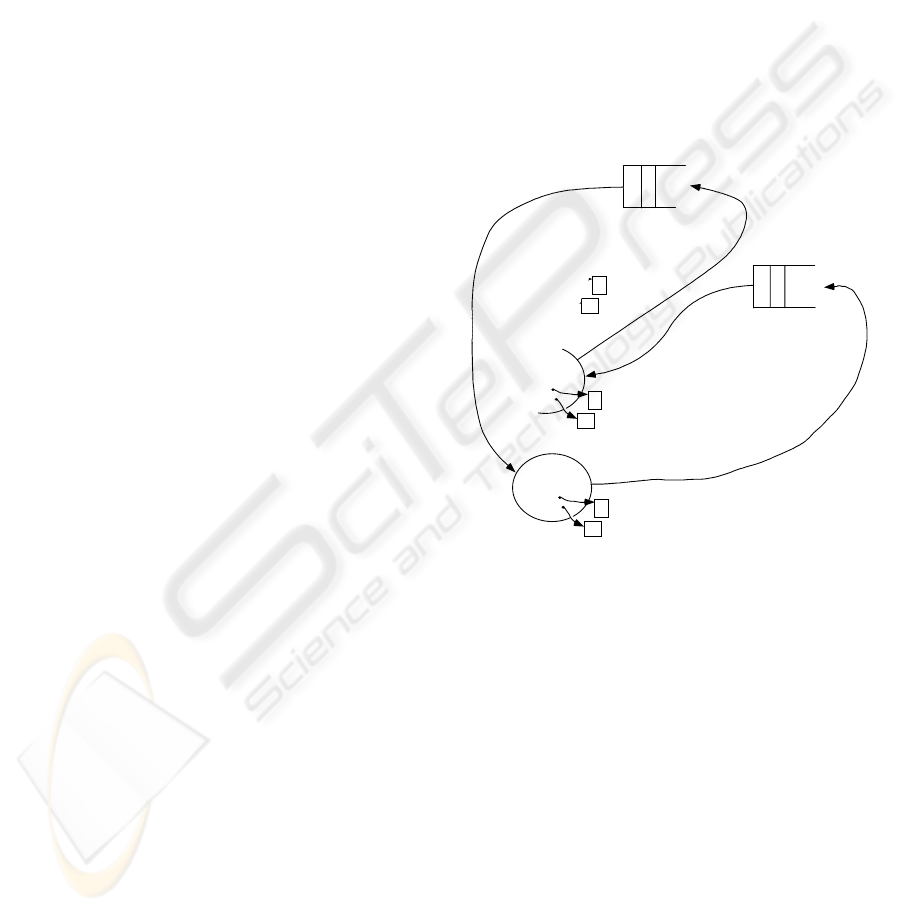
Global Event List
Message Relay
1
2
3
Figure 3: Simulation involving 3 models
The events in the global event list tell which
submodel will address the event and the time at
which the event occurs. When an event is pulled off
the list, the simulated time is then advanced to the
next event’s event time. The event type is not
recorded on the global event list, as this information
is contained within the submodel’s local event list
and need not be duplicated. The coordination
function then calls the appropriate submodel and
passes it the current simulated time. The submodel,
knowing that it is responsible for executing the next
event, pulls the next event off its local event list and
executes it. As stated above, it only executes its
executive function’s event processing cycle up to the
point where the communication lines are to be
checked. At this point, program control is returned
to the coordination function where the function then
checks the message relay and continues its cycle.
See Figure 3 above.
ICEIS 2005 - INFORMATION SYSTEMS ANALYSIS AND SPECIFICATION
148
6 AN ILLUSTRATIVE EXAMPLE
The following section illustrates an example of a
real physical system that is controlled using a
distributed model. A simulation using the same set
of distributed models for the considered system is
also performed. Each of the sub models for the
included controllers was programmed using the
simulation tool discussed above. In Gonzalez and
Davis (1998b), the physical system is discussed in
greater detail while in Gonzalez and Davis (1997)
the employed simulation model is discussed.
The physical system is a model of a flexile
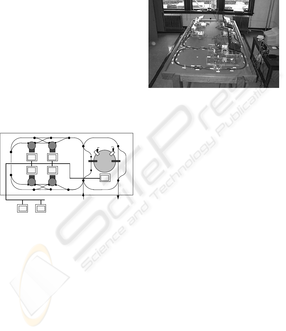
manufacturing system. The schematic for the
constructed FMS emulator is shown in Figure 4 and
a photograph is depicted in Figure 1. This model
provides a testbed for the development of the
simulation and control tool that is needed to manage
the system. Note that since we are assuming the
system is a real FMS, we thus have modeled it using
a collection of independent models.
Machine 1
Machine 4
Machine 2
Machine 3
Fixturing
Stations
1 and 2
Dedicated LAN
Cell
Co
n
t
r
olle
r
MHS (PLC)
Co
n
t
r
olle
r
To Network Server
5
f
t
.
x
10
f
t
.T
a
b
le
HO Gauge Train Track
Entry Point
from Shop Level
Exit Point
to Shop Level
Figure 4: Schematic for the constructed FMS physical
model.
The emulator has four Processing Centers,
numbered 1 through 4. Each Processing Center (PC)
contains one primary processing resource and a
dedicated Material Handling System (MHS). Within
the emulated FMS (see Figure 3), another process is
the Fixturing Center (FC). The FC has a dedicated
MHS consisting of a primary carousel capable of
holding sixteen jobs and two smaller carousels for
loading and unloading jobs from the Automatic
Guided vehicle (AGV). The movement of these
carousels is controlled by a dedicated controller.
The FC has two fixturing positions that represent the
subordinate unit processes. The final subordinate
process is the cell’s MHS. AGVs are employed as
the primary material handlers at the cell level and
are modeled with an HO-scale electric train. In this
layout, there are over forty track segments that can
be individually powered. Sensory switches are
provided on each track segment to detect the
presence of an AGV.
Figure 5: Photograph of the hardware model
In constructing this control architecture, 25
independent copies of the simulation tool was
employed, each with its own model of the subsystem
that it is addressing and all running concurrently, see
Figure 1. The only thing that ties them together into
a single-control architecture is the communication
among them. The communication is performed
across a local area network (LAN) connecting seven
computers where the cell controller and each of the
cell’s six subordinate controllers are situated on their
own computer. Additional communication links are
provided via RS-232 links between the FC and PC
controllers and their dedicated hardware controller
boards.
In this example, the developed model controlled
the physical system. The controller was given a total
of three jobs, each with two processing steps. Each
processing step required the part to be moved to a
different machine. In addition to the processing of
the part, before and after each processing step the
part had to be moved to the fixturing center for
fixturing. There were four Sun Work stations and six
controller boards. The software controllers were
distributed among the four workstations. Each
controller board controlled the hardware that was
attached to it. The same model was employed to run
the simulation in order to project the future
performance of the system given its current state.
The state of the hardware is used to initialize the
state of the simulation models. However since they
are in fact the vary same software code the state
transfer simply represents a straight forward
initialization of each variable in the simulation
model from the corresponding variable in the control
model. No interpretation as to the physical meaning
of these variables data is necessary. The message
transcript for both the actual run and the simulation
run were similar. The only difference was due to the
MODEL SHARING IN THE SIMULATION AND CONTROL OF DISTRIBUTED DISCRETE-EVENT SYSTEMS
149

discrepancy between the estimated and actual
duration times. No changes had to be made to any
of the models in order to switch from using them for
control or simulation.
Since there is no tool that can accept a collection
of models, simulating this system with commercial
simulation software like ARENA will be impossible.
The method that is commonly used to model
distributed systems is to create a new equivalent
simulation model that is not distributed. This
however represents a considerable modeling effort.
For example, the complete modeling effort for our
system, including the models for control as well as
the simulation models, is cut by 72% over using a
conventional modeling tool. Using a conventional
tool would have resulted in a modeling effort
equivalent to writing models for 88 units where as
we only wrote 25 models, one for each of the 25
units. And this does not include the extra modeling
effort that goes into modeling the communications
among the controllers, which, for our system is
integrated into the tool and therefore represent no
additional modeling. If one wants to incorporate
simulation at different resolutions then this requires
additional modeling using a commercial tool. Our
tool provides all levels of resolution using the basic
set of models. One simply includes those models
whose logic we want represented.
7 CONCLUSIONS
The distributed simulation and control system was
successfully tested on our physical simulator of an
FMS consisting of 4 single processor machines, 1
double processor machine and an automated guided
vehicle system. For the sake of demonstration the
system used 6 independent computers to control the
hardware. Real-time simulations of the distributed
controller using our methodology were concurrently
executed using the same control models. The
simulations were initialized to the current state of
the hardware before starting. This allows the
simulations to produce future predictions.
We have shown an implementation of a tool that
along with a coordination object can simulate a
distributed system using the individual models. The
key issue for this implementation to work is our
distributed modeling methodology where each
individual simulation object is included into the
simulation program and the coordination function
coordinated the execution of each simulation object
to model the concurrent processing. The
coordination function uses its global event list to
organize the execution of the simulation object by
chronological order. The simulation objects in tern
only execute the immediate event and do not cycle.
One of the most important advantages of using
the same models for both simulation and control is
that the state definition is simply the data in the
variables of the models. This allows for the
simulation to be initialized with the current state of
the controller with only a trivial copying of the data
to a 2nd copy of the model. This solves a major
problem in control. That is, the state does not need
to be interpreted to meaningful information to
initialize a different model.
REFERENCES
Albus, J. S. and A. Meystel, 1997, “Behavior Generation
in Intelligent Systems,” National Institute of Standards
and Technology Internal Report, Gaithersburg, MD.
Albus, J. S. and A. Meystel, 1995, “A reference model
architecture for design and implementation of semiotic
control in large and complex systems” In
Architectures for Semiotic Modeling and Situation
Analysis in Large Complex Systems: Proceedings of
1995 ISIC Workshop, 33- 45, AdRem Press, Bala
Cynwyd, Pennsylvania.
Arango G., and R. Prieto-Diaz, 1991, “Domain analysis:
concepts and research directions,” Domain Analysis
and Software Systems Modeling, Los Alamitos, CA:
IEEE Computer Society Press, pp. 9-33.
Bodner D. A., S. A. Reveliotis, 1997, “Virtual factories:
an object-oriented simulation-based framework for
real-time FMS control,” Proceedings of the 6th
International Conference on Emerging Technologies
and Factory Automation, pp. 208 –213.
Davis W. J., D. Setterdahl, J. Macro, V. Izokaitis, and B.
Bauman, 1993, “Recent Advances in the Modeling,
Scheduling and Control of Flexible Automation,”
Proceedings of the 1993 Winter Simulation
Conference, pp. 143-155.
Davis W. J., 1998, “On-Line Simulation: Need and
Evolving Research Requirements,” Simulation
Handbook, J. Banks, ed., Wiley, pp. 465-516.
Gonzalez F. G., W. J. Davis, 1997,"A Simulation-Based
Controller for Distributed Discrete-Event Systems
with Application to Flexible Manufacturing,"
Proceedings of the 1997 Winter Simulation
Conference, pp. 845-853.
Gonzalez F. G., W. J. Davis, 1998a,"Initializing On-Line
Simulations From the State of a Distributed System,"
Proceedings of the 1998 Winter Simulation
Conference.
Gonzalez F. G., W. J. Davis, 1998b, "Developing a
Physical Emulator for a Flexible Manufacturing
System," Proceedings of the 1998 International
Conference on Systems, Man and Cybernetics.
ICEIS 2005 - INFORMATION SYSTEMS ANALYSIS AND SPECIFICATION
150

Gonzalez F. G., A. Helton, D. Helton, J. Smith, E.
Thompson, G. Walterscheild, 2000, "The Design of a
Solid-State Physical Model of an Automated System
to be used as a Test Bed for Control Applications,"
Proceedings of the 2000 Winter Simulation
Conference.
Gonzalez F. G., W. J. Davis, 2003, "A New Simulation
Tool for the Modeling and Control of Distributed
Systems," SIMULATION the Journal of the Society for
Computer Simulation International, Vol. 78, Issue 9,
Sept. 2002.
Gonzalez F. G., 2004, “Intelligent Control of Distributed
Large Scale Manufacturing Systems,” Proceedings of
the 2004 National Science Foundation Design, Service
and Manufacture and Industrial Innovation Grantees
and Research Conference.
Govindaraj T., L. F. McGinnis, C. M. Mitchell, D. A.
Bodner, S. Narayanan and U. Sreekanth, 1993,
“OOSIM: A Tool for Simulating Modern
Manufacturing Systems,” Proceedings of the 1993
National Science Foundation Grantees in Design and
Manufacturing Conference, pp. 1055-1062.
Kelton W. D., R. P. Sadowski, and D. A. Sadowski, 2001,
Simulation with ARENA, McGraw-Hill, 2nd ed.
Mize J. H., H. C. Bhuskute, and M. Kamath, 1992,
“Modeling of Integrated Manufacturing Systems,” IIE
Transactions, vol. 24, no. 3, pp.14-26.
Narayanan S. D., A. Bodner, U. Sreekanth, S. J. Dilley, T.
Govindaraj, L. F. McGinnis and C. M. Mitchell, 1992,
"Object-Oriented Simulation to Support Operator
Decision Making in Semiconductor Manufacturing,"
Proceedings of the 1992 International Conference on
Systems, Man and Cybernetics, pp. 1510-1519.
Peters B. A., J. S. Smith, J. Curry and C. LaJimodiere,
1996, “Advanced Tutorial - Simulation Based
Scheduling and Control,” Proceedings of the 1996
Winter Simulation Conference, Eds. J. M. Charnes, D.
J. Morrice, D. T. Brunner and J. J. Swain, pp. 194-198.
Smith J. S., R. A. Wysk, D. T. Sturrock, S. E.
Ramaswamy, G. D. Smith and S. B. Joshi, 1994,
“Discrete Event Simulation for Shop Floor Control,”
Proceedings of the 1994 Winter Simulation
Conference, pp. 962-969.
Smith J. S., B. A. Peters, 1998, “Simulation as a decision-
making tool for real-time control of flexible
manufacturing systems,” Proceedings of the 1998
International Conference on Robotics and
Automation, pp. 586-590.
Stecke K. E., 1985, “Design, planning Scheduling and
Control problems of flexible manufacturing systems,”
Annals of Operation Research, vol. 3.
MODEL SHARING IN THE SIMULATION AND CONTROL OF DISTRIBUTED DISCRETE-EVENT SYSTEMS
151
