
DESIGNING GEOGRAPHIC ANALYSIS PROCESSES ON
THE BASIS OF THE CONCEPTUAL FRAMEWORK
GEOFRAME
Cláudio Ruschel, Cirano Iochpe, Luciana Vargas da Rocha
Universidade Federal do Rio Grande do Sul, Caixa Postal 15064,
91501-970 Porto Alegre, RS, Brazil
Jugurta Lisboa F.
Universidade Federal de Viçosa, Campus Universitário,
36570-000 Viçosa, MG, Brazil
Keywords: Geographic Information Systems, Geographic Analysis Process, UML
Abstract: The investment in geographic in
formation systems (GIS) is usually justified by their ability of supporting
the execution of geographic analysis processes (GP). The conceptual design of a GP makes it independent
of a specific GIS product and enables designers to define the process at a high level of abstraction using a
language that enforces a set of logical constraints and is yet easy to learn. On the other hand, in order to
support interoperability a GP conceptual model should be sufficiently generic to allow a GP definition to be
translated to any of the logical data models implemented by existing GIS commercial products. This paper
presents an extension to GeoFrame, a conceptual GIS framework that supports the conceptual design of
spatio-temporal, geographic databases (GDB). This extension is actually a conceptual GP data model
relying on a set of UML diagrams as well as on a methodology of how to apply them to analysis process
design. On the basis of the PGeoFrame-A, the definition of a GP starts by the identification of its associated
use cases. Both control and data flows are described by means of activity diagrams with the new modeling
constructs provided by UML 2.0. Input as well as output data introduced in the workflow definition are
described in detail through a class diagram. In this way, CASE tools based on UML can be adapted to
translate GP conceptual design to the specific scripts as well as macro definition languages of different
existing GIS products.
1 INTRODUCTION
Knowledge about the space we live in has always
been of a great value to mankind. A few centuries
ago the geographic information we counted with was
not accurate, scarcely arranged, and almost
unavailable. Nowadays, many of these limitations
are not present anymore. Geographic information
captured by techniques that guarantee high precision
can be found in abundance and represent almost all
regions of the earth in different projections as well
as scales.
Currently, spatial and descriptive information are
kept
i
ntegrated in geographic databases (GDB).
These information is usually presented as well as
processed by so-called geographic information
systems (GIS). The investment necessary to build a
GDB is usually justified mostly by the results that
can be achieved from the geographic analysis
processes (GP) to be carried out at system’s
production time. The complexity of a GP may range
from a simple query to an intricate algorithm of
spatial analysis.
A GP can also be understood as a workflow that
defi
nes a
partial order of execution of a set of GIS
operations. For instance, in the context of an
environmental application, a GP can rely on a set of
user-defined selection criteria to process the GDB
and suggest best locations for ecology-preserving
national parks. Depending on the GIS, the GP can be
programmed either directly at the user interface or
through a specific API that provides a library of
geographic operations.
91
Ruschel C., Iochpe C., Vargas da Rocha L. and Lisboa F. J. (2005).
DESIGNING GEOGRAPHIC ANALYSIS PROCESSES ON THE BASIS OF THE CONCEPTUAL FRAMEWORK GEOFRAME.
In Proceedings of the Seventh International Conference on Enterprise Information Systems, pages 91-97
DOI: 10.5220/0002533300910097
Copyright
c
SciTePress
The knowledge of the main GPs that will be
executed at system’s production time is of
fundamental importance to the design of the GDB as
well as by the selection of the GIS software and the
metadata configuration for the geographic datasets
that will be acquired. Therefore, GIS software tools
should support the conceptual design of GP.
Though, most products support neither end-user
interface nor API for GP conceptual design.
Usually, commercial GIS products support an
operation interface, at the logical level, that
implements a variation of the so-called cartographic
modeling technique as it was proposed by Tomlin
(Tomlin, 1991). In the cartographic modeling each
data set is considered a layer. The notation usually
represents layers by their names involved in a box,
while the functions (or operations) that act on these
data are indicated over oriented arcs between boxes.
The cartographic model of most products completely
hides the database sub-schema that lies below the
concept of a layer. At the GDB logical level, a layer
may be either a table, or a complex view created by
some join operation over a number of tables.
Several specific conceptual models for GDB
design have been proposed and improved during the
last years. In the literature, one can find the
GeoOOA (Kösters, 1997), GMOD (Oliveira, 1997),
MADS (Parent, 1999), and OMT-G (Davis, 1999)
among others. Most of them support the design of
static aspects of the GDB (e.g. classes and
associations). GMOD is one of the few models that
enable designers to represent dynamic aspects such
as the causal relationship between classes (e.g. the
occurrence of rain for a certain period of time may
cause an occurrence of a flood in a certain region).
On the basis of a so-called transformation diagram,
the OMT-G support the modeling of the internal
aspects of a process, including geographic analysis
operations, relying on its own semantics definition.
This paper presents a solution to the specification
of geographic analysis processes at the conceptual
level, regarding both external and internal aspects,
through an extension of resources offered by the
conceptual framework GeoFrame (Lisboa, 1999).
Since GeoFrame is based on UML, GPs can be
defined in a high level language that is independent
of a specific GIS product. By adapting UML CASE
tools, it is possible to support interoperability for a
GP by translating its UML definition onto a
definition accepted at the interface of any GIS that
supports the types of operations provided at the
conceptual level.
The remainder of this paper is organized as
follows. In section 2, the conceptual framework
GeoFrame introduced. In section 3 a classification of
geographic analysis operations is presented. Main
operation categories are supported by the GeoFrame
extension to GP conceptual design (PGeoFrame-A).
GP design with the proposed GeoFrame extension is
discussed in section 4. The steps of a GP design are
illustrated by means of an example in section 5.
Section 6 concludes the paper and points out to
future work.
2 THE CONCEPTUAL
FRAMEWORK GEOFRAME
GeoFrame is a conceptual framework with basis on
the formalism of object orientation that makes use of
the UML language. The framework concept adopted
in the GeoFrame is the one of a generic design in a
domain that can be adapted to specific applications
in order to serve as a pattern for construction of
applications.
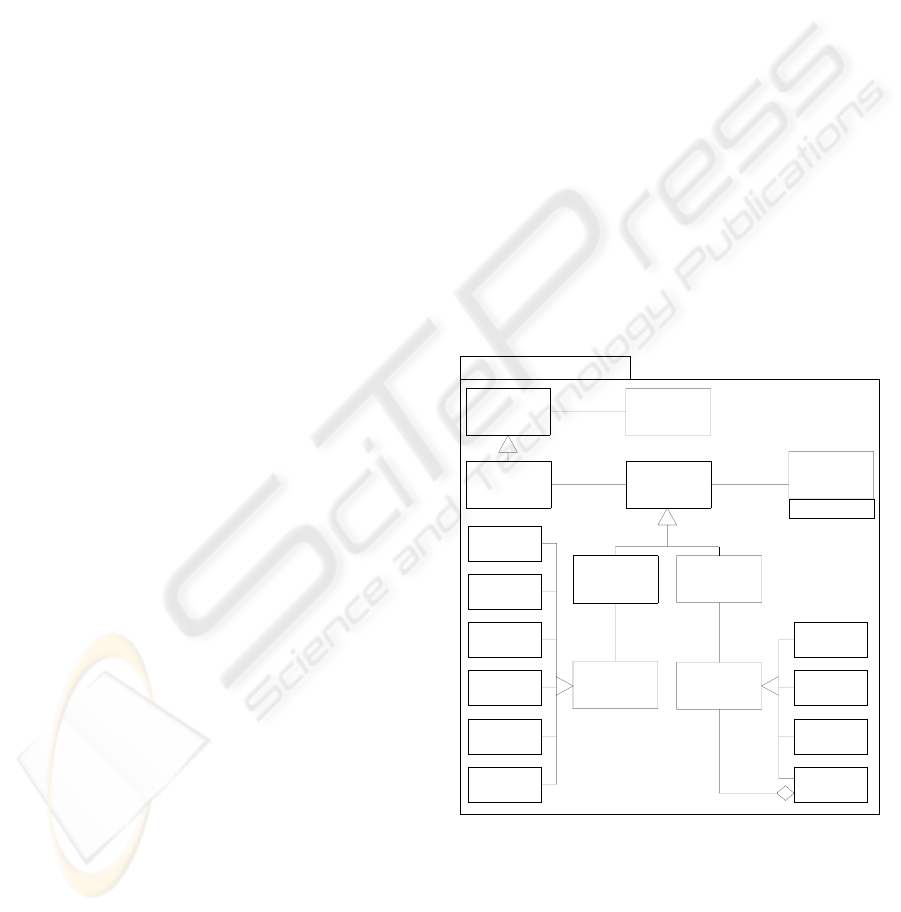
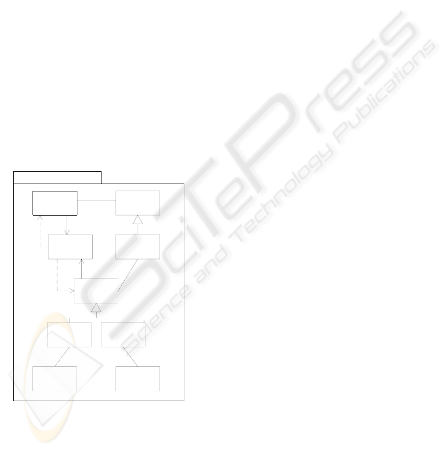
The framework offers a class diagram, which is
specified in the PGeoFrame
package (shown in
Figure 1) (Lisboa, 2002), where each package has
the classes that are used as a basis for modeling of
classes of a GIS application. The data schema
produced with usage of this framework can be
denominated as UML-GeoFrame schema.
Field
Geographic
represent represent
**
0...1 1...*
PGeoFrame
NonGeographic
Object
Object
Spatial
Complex
SpatialObj
Polygon
Line
Point
Isolines
Irregular
Points
Grid
OfCells
Adjacent
Polygons
GridOf
Points
TIN
Region
Geographic
description
continence
1...*
0...1 1...*
Field
Representation
*
Metadata
Phenomenon
Geographic
Geometadata
Object
Geographic
Figure 1: The GeoFrame’s class diagram
An extension to the PGeoFrame package, which
stands temporal aspects, was proposed by Rocha
(Rocha, 2001), who introduced the PGeoFrame-T
package, that imports the PGeoFrame. Therefore, the
GeoFrame user has two alternatives of modeling. To
model only the spatial aspects of a GDB, only the
PGeoFrame package must be used. Nevertheless, to
ICEIS 2005 - HUMAN-COMPUTER INTERACTION
92
express the temporal aspects as well, the
PGeoFrame-T must be used.
To specify the GDB conceptual schema of an
application, the user sets forth classes of application
as a specialization of the GeoFrame classes.
Afterwards he forms groups with more similar class
features in different themes, according to the
application requirements, whereby for each theme a
class diagram is developed using the UML
resources.
The objects that have a spatial component are
instances of the GeographicPhenomenon
class,
while the others, which are also denominated
descriptive objects, are instances of
NonGeographicObject classes. Following the sight
dichotomy principle of fields and objects introduced
by Goodchild (Goodchild, 1990), in the GeoFrame
the GeographicPhenomenon class is specialized in
the GeographicObject and GeographicField classes,
which are respectively represented by SpatialObject
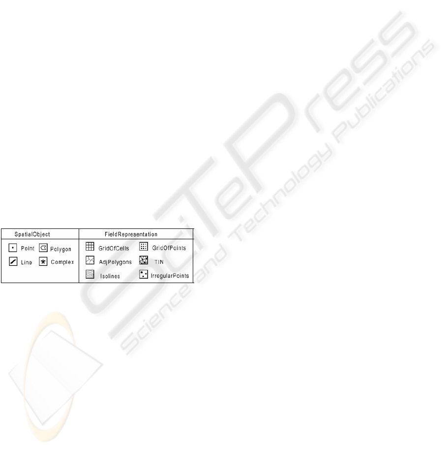
and FieldRepresentation. According to what is
shown in the Figure 2, the spatial representation is
indicated through a set of stereotypes, introduced as
pictograms at the upper right corner of the rectangle
that indicates the class.
The conceptual framework GeoFrame differs
from the other conceptual models with regard to
types of geographical data when it searches a total
compatibility with the UML language. The UML-
GeoFrame schemes can be constructed with CASE
tools able to present pictogram-shaped stereotypes.
Figure 2: The GeoFrame’s stereotypes
So that the GeoFrame may also be used to
describe the dynamic aspects of a GDB it is
necessary to have an incorporation of resources, as
described below:
– To offer a catalog with geoprocessing
operations, in such a way that they may be used
in processes specification;
– Ability to express in a class diagram the
associations amid both original and derivative
classes that result from geographic analysis
processes;
– To offer a methodology that allows a
specification of the geographic analysis
processes, with usage of other UML resources
not explored yet, like the behaviour diagrams or
the processes expression in the classes diagram.
3 CLASSIFICATIONS OF
GEOGRAPHIC ANALYSIS
OPERATIONS
The spatial nature of geographical data allows that
geometric operations and topologic functions be
applied to them. The way such operations must be
arranged in groups is still a point at issue in the
geoinformation field. Due to a diversification of
concepts and nomenclatures on the geographic
analysis operations, the designer who wishes to
make clear the usage of these operations, while they
are still in the conceptual period, will be facing
knotty problems.
The basic set of operations has been formed from
the classification developed by Albrecht (Albrecht,
1996), whereby concepts developed by other authors
were also aggregated (Aronoff, 1989), (Câmara,
2000), (Chrisman, 1997), (Davis, 1999), (Open GIS
Consortium, 2001), (Tomlin, 1991) leading it to
suppression and addition of operations to that
classification. For every operation the possible entry
parameters and types of results have been
determined according to the GeoFrame expected
representations. We have opted to use
specializations for the data types, whenever possible,
so that when any field or object representation is
applicable, it is possible to make use of
GeographicObject and GeographicField classes.
Only if any spatial representation is applicable the
GeographicPhenomenon general class is used. The
following list presents a synthetic description of the
operations defined in the GeoFrame catalog
(Ruschel, 2003):
– Selection: or "Non-Spatial Selection", it restrains
the set of GeographicPhenomenon instances, on
which it is applied, for instances that fulfill the
selection attribute.
– Spatial Selection: it restrains the set of
GeographicObject instances, on which it is
applied, for the instances that fulfill a spatial
predicate related to a GeographicObject of
reference.
– Region Selection: similar to the Spatial
Selection, it uses a settled spatial predicate, the
“inside” topologic restraint, applicable to any
GeographicPhenomenon. The region is
determined by one and only Polygon instance or
by GeographicField.
– Classification or Algebra: it only handles with
those values associated to the
GeographicPhenomenon. This definition
includes the majority of Tomlin´s map algebra
operations (Tomlin, 1991).
DESIGNING GEOGRAPHIC ANALYSIS PROCESSES ON THE BASIS OF THE CONCEPTUAL FRAMEWORK
GEOFRAME
93
– Buffer: it establishes a region founded in the
distances related to a GeographicPhenomenon of
reference.
– Overlay is a boolean or mathematic operation
applied in a pair of GeographicPhenomenon.
When only GeographicObject instances are
involved, a geometric processing is carried out
and the result presents new instances including
the attribute set of the original instances.
– Voronoi Diagram: construction of a Tessellation,
according to a set of points, so that each polygon
may contain the points of the plan closer to a
specific place, instead of any other place.
– Slope: applicable from an instance of
GeographicField of continuous distribution, with
values that may be discretisized in plans.
– Viewshed: it classifies a GeographicField as
"visible" or "non-visible", according to a spot or
region defined at a determined elevation over the
ground.
– Spread: it is applied both to a net topologic
structure and a GeographicField instance. It
takes into consideration the existence of a
starting point and values, generically called a
cost, in its structure, having as a result paths of
minor cost.
– Transform: calculation of the coordinates
amounts of any GeographicPhenomenon for a
system of cartographic projection different from
the original.
– Distance: it returns the distance between two
GeographicObject instances.
– Centroid: attainment of a point in a secure way
within a polygon, useful for generation of
topology in vectorial GIS.
– Dissolve: when the spatial relationship of two
instances of a GeographicObject class is of
vicinity and both possess the same value for a
determined attribute, they are aggregated into
one only instance.
– Interpolation: according to Geographic
Phenomenon instances, an interpolation method
is applied (ex: polynomial regression, Fourier,
Kriging) to get another set of data as a result,
which inclusively may have another
representation format. Some methods may
require additional numeric parameters.
4 SPECIFICATIONS OF
GEOGRAPHIC ANALYSIS
PROCESSES
According to Booch (Booch, 1999), the UML
(Unified Modeling Language) is a language for
specification, mainly for complex systems of
software. However, it is also enough expressive to
model systems that are not software.
To model geographic analysis processes, we
have opted for the adaptation of RUP (Rational
Unified Process) methodology, for development of
software using the UML. The simplified method
described in (Quatrani, 1997) has been utilized.
Instead of starting the acquirement of necessary
data directly from the class diagram, RUP suggests
that such acquirement be started through the use
case diagram. Our attempt is to find out “what” the
system must do. In this diagram the actors, the use
cases and the relationships among the use cases are
identified.
This methodology will be presented in the
sequence together with an example in the basic
sanitation field. In our example, we attempt to
determine the water pressure surface in a supplying
system portioned with several reservoirs.
Generate Terrain Surface
Generate Piezometric Surface
Water Supply Department
Generate Pressure Surface
<<include>>
<<include>>
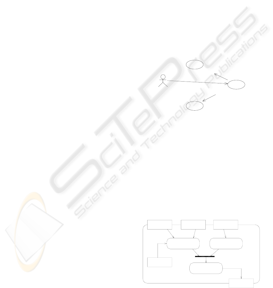
Figure 3: Initial use case diagram
The example presented in the Figure 3 shows an
use case diagram, where the use case “Generate
Pressure Surface”, requested by an user of the Water
Supply Department, includes the use cases
“Generate Terrain Surface” and “Generate
Piezometric Surface”. It means that the water
pressure depends on the height values of the natural
terrain and on the height of the piezometric line in
every spot.
At this point of modeling, preliminary activity
diagrams may be created to show the flow through
use cases, or inside a particular use case.
Contours
Surface
Generate Terrain
Reservoirs
Generate Piezo-
metric Surface
Systems
Calculate Surfaces
Difference
Water Pressure
Surface
Head Loss
Function
Figure 4: Example of preliminary activity diagram
ICEIS 2005 - HUMAN-COMPUTER INTERACTION
94
The example presented in the Figure 4 furnishes
a preliminary identification of objects to be used and
the actions to be taken. To generate the terrain
surface, a set of contours is required. To generate the
piezometric surface, one needs the water system
limits and the reservoir responsible of the water
supply for that system. A head loss function is also
required, obtained from the pipes properties. The
difference calculated of these two surfaces generates
the water pressure surface.
For the next phases of modeling the semantics
introduced in version 2.0 of UML (OMG, 2004) is
used. The modeling element Activity, specialization
of Class in the UML metamodel is defined as a
specification of parameterized behavior. Therefore,
an Activity may be represented in the class diagram
or have its behavior detailed in the activity diagram.
By applying this semantics to proposal of
GeoFrame extension, after it has been identified, a
Geographic Analysis Process (GP) must be modeled
as an UML Activity class and expressed in the class
diagram. This class possesses associations with
classes of the user model that furnish entrance
parameters and as a result of its instantiation, some
instances of geographic classes or not. In the
GeoFrame such kind of classes may be plainly
called Process.
The class diagram in the Figure 5 formalizes the
list of all elements that have been identified. The
objects that appeared in the preliminary activity
diagram now are arranged in classes. The GeoFrame
pictograms indicate the spatial representation of
each class, with exception of the pictogram that
shows a gear, thus indicating that the class belongs
to the Process type. So, the classes
WaterSupplySystem, Reservoir and Terrain supply
instances to the process CalculatePressureSurface.
As an exit of this process, new instances of the
WaterPressure class are created.
The details on behavior of the classes inserted as
Process in the user model appear through the
refinement of the activity diagram. At this level of
details the operations of geographic analysis should
already be evident. In the UML the behavior of an
Activity is characterized as a sequence of
subordinated units where each individual element is
an Action.
Terrain
Reservoir
System
Pressure
Water
WaterSupply
Calculate
<<instantiate>>
Surface
Pressure
Figure 5: Class diagram incorporating a class of
Process type
Just like a GP defined by the user, the GeoFrame
catalog operations should be modeled as activities
invoked in an activity diagram through an action of
the kind of "CallBehaviorAction". Taking into
consideration that such operations are already
implemented in the GIS software to be used for the
GP execution, there is no need to have them
detailed. Other actions, like the “Read/Write Action”
and “ComputationalAction” will be necessary to
complete the diagram. An Action is represented as a
round square in this diagram.
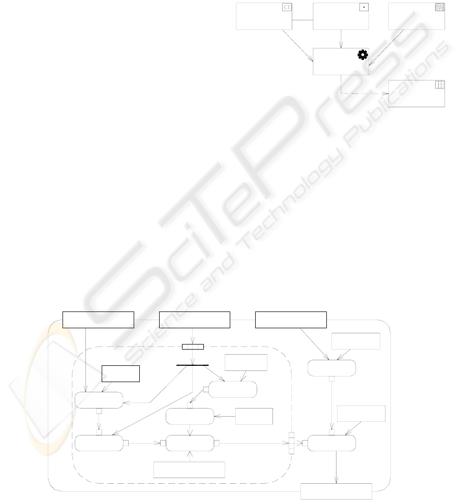
In the example of Figure 6 the operations Spatial
Selection, Buffer, Classification, Overlay and
Interpolation have been used.
CalcPressureSurface
Water Pressure Surface
Difference: Text
Linear: Text
GridOfCells
Interpolation
Overlay
GridOfCellsGridOfCells
elev: Variable
Classification
elev-[v]*3/100: Text
WriteVariable
ReadAttribute
elevation: Attribute
reference
Polygon
restriction
Buffer
contain: Text
SpatialSelection
Contour SetReservation Set
Systems Set
Figure 6: Activity diagram of a Process class
DESIGNING GEOGRAPHIC ANALYSIS PROCESSES ON THE BASIS OF THE CONCEPTUAL FRAMEWORK
GEOFRAME
95
Besides these operations, in this activity diagram it
is possible to highlight the application of the
following modeling elements (OMG, 2004):
– Object node: represented with an rectangle, it
holds all kinds of data that is involved in the
process.
– Data flow and pins: the pins (little squares) at the
extremities of the arches represent a temporary
object that flows between actions.
– Expansion region: it is represented as an activity
in a broken line and is executed as many times as
is the number of elements of an entrance
collection.
– Expansion node: it is situated at the edge of the
expansion region. The entrance node maintains
an element separated from the collection during
each execution of the region. The exit node
accepts one element of every execution of the
region, making available a collection in case of a
complete execution of the region.
To avoid any harm to GeoFrame framework
original structure, necessary adaptations to make
modeling possible have been developed in a new
package called PGeoFrame-A, which also imports
the PGeoFrame
package.
Metadata
Process
Phenomenon
Geographic
Geometadata
Object
Geographic
Field
Geographic
Object
Spatial
<<instantiate>>
<<instantiate>>
represents represents
Field
Representation
**
0...1
parameter
parameter
1...*
0...11...*
PGeoFrame-A
NonGeographic
Object
Figure 7: Class diagram of the PGeoFrame-A package
Within this same logic, the designer who
attempts to represent analytical processes with the
GeoFrame (Rocha, 2001) must use the PGeoFrame-
A. Simultaneous utilization of processes and
temporality in the same model is the purpose of
future works.
The Process class has been incorporated to the
PGeoFrame-A
package, as shown in the Figure 8.
This class is associated with classes that provide
entrance parameters, the same way they can provoke
the creation of new instances of NonGeographicObject
and GeographicPhenomenon.
5 RELATED AND FUTURE
WORKS
A series of projects is under development in parallel,
like:
– GisCase; the GisCase project implements a
CASE tool, in free software, that allows
modeling of GP and, with use of components of
libraries that can execute geographic analysis
operations, code generation. When this code is
compiled and executed, it access a GDB where
the input data are read and the generated data are
stored. The initial implementation is being built
with the Poseidon for UML Community Edition
CASE tool (Gentleware, 2004) and the TerraLib
library (Câmara, 2004), generating code in XML
and C++. However, the architecture of this tool
supports implementation with other CASE tools
and libraries;
– InterSIG: the InterSIG project intends to
complement and extend the GeoFrame-T
framework to modeling of spatial-temporal GDB
and documentation of analysis patterns for GDB,
as a base for construction of a geographic
catalog system;
– ArgoCASEGeo: is also a CASE tool under
development which the main propose is to
explore how an Analysis Patterns Catalog can
improve the GIS users’ productivity and the
GDB quality (Lisboa, 2004). This tool
transforms conceptual data schemas into logical
implementation of ArcView GIS, Geomedia GIS
and TerraLib library.
Taken as possible future works related to
geographic analysis processes, one can mention
integration of PGeoFrame-A and PGeoFrame-T
packages; examination of applicability of other
resources introduced by version 2.0 of UML and not
utilized in this work; and the organization of
catalogs of GP, in a format analogous to the
GeoFrame analysis patterns.
6 CONCLUSIONS
This paper has presented a method to specify
geographic analysis processes compatible with the
UML language, so that the user can be able to
develop the model diagrams in a compatible CASE
ICEIS 2005 - HUMAN-COMPUTER INTERACTION
96

tool. With these tools it is possible to not only
construct the GBD schema but even generate
executable code.
This method is based upon a conceptual
framework, the GeoFrame, which offers resources
that simplifies the usage of UML in the elaboration
of GDB conceptual schemas. The proposed
extension follows the same line, except that now it
simplifies the usage of UML at the specification of
geographic analysis processes.
The solution presented as a whole has been
incorporated to the PGeoFrame-A package, which
imports the contents from the original framework,
the PGeoFrame package. In a synthetic way, the user
of this framework who may choose to use the
PGeoFrame-A will find semantics that supports the
expression of geographic analysis processes,
together with a catalog of expandable operations.
Besides that, with utilization of GeoFrame it is
possible to develop a catalog of analysis patterns
that will progress along the time it is used. In a
similar way, our intent is to offer together with the
GeoFrame extension for specification of GP a basic
catalog for operations. This catalog has to be
independent of software and be able to be enlarged
by the user, according to the requirements of the GP
that may be implemented on the GDB.
ACKNOWLEDGEMENTS
This work has been partially supported by CNPq
(Brazilian National Research Council), the Brazilian
governmental agency for scientific and technological
development.
REFERENCES
Albrecht, J., 1996. Universelle GIS Operations for
Environment Modeling. In Proceedings of the 3.
nd
International Conference on Integrating GIS and
Environmental Modeling. Santa Barbara.
Aronoff, S., 1989. Geographic Information Systems: a
management perspective. WDL Publications, Ottawa.
Booch, G., Jacobson, Y., Rumbagh, J., 1999. The Unified
Modeling Language User Guide. Addison-Wesley,
New York.
Câmara, G., et al., 2000. Towards a Unified Framework
for Spatial Data Models. J. Braz. Comp. Soc. Porto
Alegre, 7(1), 17 – 25.
Câmara, G., Onsrud, H., Monteiro, A.M.V., 2004.
Eficcacious Sustainability of GIS Development within
a Low income Country: The Brazilian Experience.
INPE. In: www.dpi.inpe.br/terralib.
Chrisman, N., 1997. Exploring Geographic Information
Systems. John Wiley & Sons, New York.
Davis Jr, C. A., Laender, A. H. F., 1999. Multiple
representations in GIS: materialization through map
generalization, geometric, and spatial analysis
operations. In Proceedings. 7th ACM GIS, Kansas
City, 60--65.
Gentleware, 2004. Poseidon for UML.
www.gentleware.com.
Goodchild, M., 1990. Geographical Data Modeling. In A.
Frank, M. Goodchild, Two Perspective on
Geographical Data Modeling. NCGIA, Santa Barbara.
Kösters, G. et al., 1997. “GIS-Application Development
with GeoOOA”. Int. Jounnal of GIS, 11(4).
Lisboa Filho, J., Iochpe, C., Borges, K. A., 2002. Analysis
patterns for GIS data schema reuse on urban
management applications. In CLEI Electronic Journal,
v.5, n.2.
Lisboa Filho, J., Iochpe, C., 1999. Specifying analysis
patterns for geographic databases on the basis of a
conceptual framework. In Proceedings 7th ACM GIS,
Kansas City, 7-13.
Lisboa Filho, J., Sodré, V. F., Daltio, J. Rodrigues Jr, M.
F., Vilela, V., 2004. “A CASE tool for geographic
database design supporting analysis patterns”.
Conceptual Modeling for Advanced Application
Domains. Proc. of ER2004 Workshop on Conceptual
Modeling for Geographic Information Systems
(CoMoGIS), Shanghai, China. LNCS 3289.
Object Management Group, 2004. UML 2.0
SuperStructure Specification. www.omg.org
Oliveira, J.L., Pires, F., Medeiros, C.B., 1997. An
Environment for Modeling and Design of Geographic
Applications. GeoInformatica, v.1, Kluwer, Boston,
29-58.
Open GIS Consortium., 2001. The OpenGIS abstract
specification, topic 1: feature geometry, version 5..
www.opengis.org.
Parent, C. et al. “Spatio-temporal conceptual models: data
structures + space + time”. In Proc.7th ACM GIS,
Kansas City, 1999.
Quatrani, T., 19997. Visual Modeling with Rational Rose
and UML. Addison-Wesley.
Rocha, L. V., Edelweiss, N., Iochpe, C., 2001. GeoFrame-
T: A Temporal Conceptual Framework for Data
Modeling. In Proc. 9th ACM GIS, Atlanta, 124-129.
Ruschel, C., 2003. Extending the Framework GeoFrame
for supporting Geographic Analysis Processes. Porto
Alegre: PPGC-UFRGS. Master Degree Dissertation
(in portuguese). www.inf.ufrgs.br/~ciochpe.
Tomlin, C. D., 1991. Cartographic Modeling. In: D.
Maguire et. al. Geographical Information Systems.
Longman, 362--374.
DESIGNING GEOGRAPHIC ANALYSIS PROCESSES ON THE BASIS OF THE CONCEPTUAL FRAMEWORK
GEOFRAME
97
