
TRANSFORMING SA/RT GRAPHICAL SPECIFICATIONS INTO
CSP+T FORMALISM
Obtaining a formal specification from semi-formal SA/RT essential models
Manuel I. Capel and Juan A. Holgado
Department of Software Engineering, Granada University, Periodista Daniel Saucedo Aranda, 18071 Granada, Spain
Keywords: Formal analysis tools, modular and s
ystematic design, process algebras, real-time systems, structured analy-
sis.
Abstract: A correct system specification is systematically obtained from the essential user requirements model by
applying a set of rules, which give a formal semantics to the graphical analysis entities of SA/RT. The aim
of the systematic procedure is to establish the methodological infrastructure necessary for deriving a com-
plete system specification of a given real-time system in terms of CSP+T processes. A detailed complete so-
lution to the Production Cell problem is discussed, showing how the method can be applied to solve a real-
world industrial problem.
1 INTRODUCTION
We present a complete bottom-up systematic
method to derive a correct system specification from
a semi-formal system requirements specification in
SA/RT (Hatley 1988, Ward 1985, Svensson 1991)
by systematically applying a set of transformation
rules. The method integrates two complementary
approaches to describe a real-time system: (1)
SA/RT based notations, and (2) CSP+T process
terms (Žic, 1994) to model real-time processes, in-
cluding the specification of their timing require-
ments.
The approach takes advantage of the long tradi-
t
ion of SA/RT graphical notations and development
methodologies in the industry and, at the same time,
aims to foster the use of Process Algebras as an ade-
quate way to overcome the intrinsic imprecision that
SA models present in describing real-time systems.
Many proposals have tried to overcome the lack
of
formal semantics of SA notations. Noteworthy
among these is the formalization of SA through Z
and Larch (Semmens, 1990), the translation from
SA to Communication Processes formalism (Fen-
cott, 1994) and the set of rules to give SA an inter-
pretation by using High-Level Petri nets (Elmstrom,
1993). However, as Baresi and Pezzè stated
(Baressi, 1998), all of these proposals irremediably
damage the flexibility of SA by assuming a given
interpretation to the ambiguity of analysis entities,
some of which should only have a weak semantics in
order to remain useful as constructs of a process
description language.
The objective of our approach follows the guide-
lin
e proposed in the latter reference, namely to over-
come the imprecision and ambiguities that the dif-
ferent families of SA notations present in describing
real-time systems. However, the proposed method
does not determine a particular semantics when there
are several possible ways to solve a given ambiguity
in an SA analysis entity. It is left up to the analyst to
select the most appropriate notation semantics, de-
pending on the system that needs to be specified.
This feature of the method is a result of the flexibil-
ity provided by the CSP+T design notation for real-
time systems.
The proposed systematic derivation technique
an
d the transformational rules can be easily inte-
grated into state-of-the-art SA/RT software tools and
the complete derivation process can be fully imple-
mented in Java with the support of CTJ (Hilderink,
2000) or JCSP (Welch, 2001) libraries. The rest of
this paper is structured as follows: first, we give
some background on SA models, which is necessary
to understand the transformation rules. In section 3,
we describe the system specification method. In sec-
tion 4, using the example of the Production Cell, we
present a complete system specification. Finally, the
conclusions and ongoing work lines are presented.
65
I. Capel M. and A. Holgado J. (2005).
TRANSFORMING SA/RT GRAPHICAL SPECIFICATIONS INTO CSP+T FORMALISM - Obtaining a formal specification from semi-formal SA/RT
essential models.
In Proceedings of the Seventh International Conference on Enterprise Information Systems, pages 65-72
DOI: 10.5220/0002523800650072
Copyright
c
SciTePress
2 REAL-TIME STRUCTURED
ANALYSIS
The methodologies and notations referred to under
the generic denomination of Structured Analysis
(SA) are mainly directed towards specifying the sys-
tem behaviour as a set of data transformations or
processes, which describe the basic functions of the
target system. The first was proposed by Ward and
Mellor (Ward, 1985) and the second by Hatley and
Pirbhai (Hatley, 1988). A third variation, called the
Extended System Modeling Language (ESML)
(Svensson, 1991) is an attempt to combine these two
approaches to the structured analysis of real-time
systems.
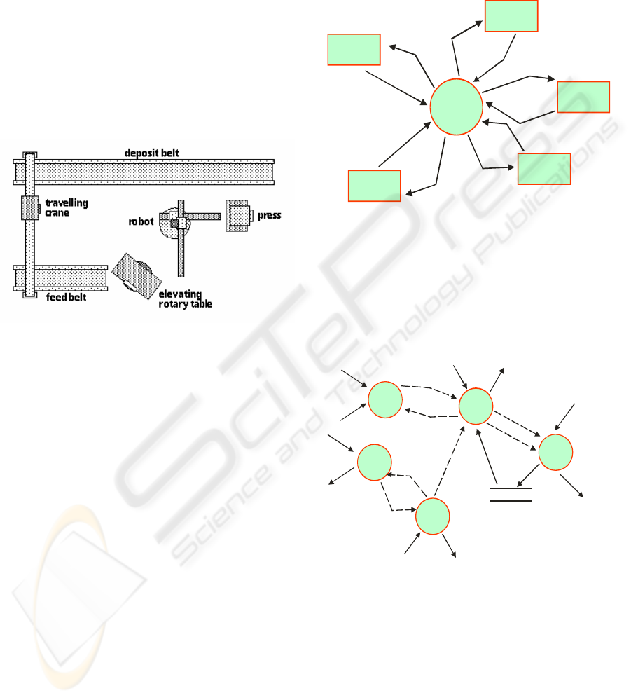
Figure 1: The Production Cell.
2.1 Production Cell Example
This well-known case study (Lewerentz, 1995),
Fig.1, presents a realistic industry-oriented problem,
where safety requirements play a significant role and
can be met by the application of formal methods. In
the fundamental configuration, the production cell
processes metal blanks that are conveyed to a press
by a feed belt. The first robot arm takes each blank
from the feed belt and places it in the press. Because
the belt and the robot are at different heights, there is
an elevating rotating table which is designed to give
blanks to the robot. The press forges a new metal
blank and opens again. Forged metal plates are taken
out of the press and put on a deposit belt by a second
robot arm. Since the robot is fitted with two arms,
the utilization of the press is enhanced, thus making
it possible for the first arm to pick up the next blank
while the press is forging another plate with the pre-
vious blank.
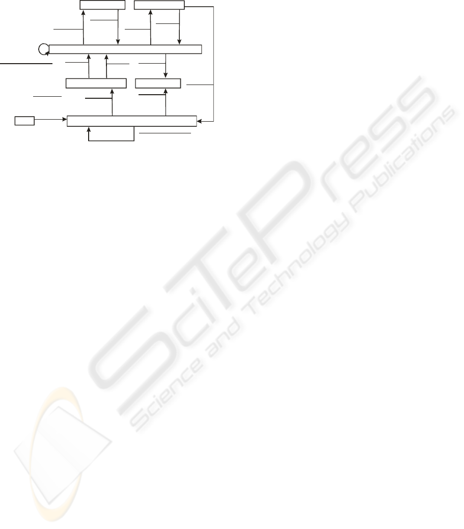
2.2 System Requirements Model
The model consists of a hierarchy of transformation
schemes rooted on the System Context Diagram
(SCD). Each scheme “explodes” into a State Transi-
tion Diagram (STD) or into a Data Flow Diagram
(DFD). The scheme denoted as SCD defines the
border between the system and the environment,
comprising the external entities (or terminators) to
the system. Fig. 2 shows an example of SCD. DFDs
may explode into new, more detailed DFDs.
Production
Cell
Control
Feeding
Belt
Rotaring
Table
Deposit
Belt
Robot
Press
press status_
fb move_
fb status_
table status_
table commands_
db move_
db status_
robot commands_
robot status_
press commands_
Figure 2: Production Cell SCD.
The DFD transformation scheme in the SA/RT
notations must include at least one Data Transfor-
mation Process (DTP), whose role is to change the
input data or event flows (control) into output flows
with no relation between the number of inputs and
outputs. The same output can be sent to several
analysis entities and a DTP must have at least one
output flow.
Feeding
Belt
Control
Table
Control
Press
Control
Robot
Control
Deposit
Belt
Control
db move_
db status_
db_w_robot
plate_dropped
plate_picked
table_w_fb
table_w_robot
blank_loaded
blank_dropped
blank_picked
fb_move
fb_status
press_sensors
press_move
table_commands
robot commands_
robot status_
table_status
Press Status
Figure 3: First level Production Cell DFD.
Control Transformation Processes (CTPs) serve
to transform inputs into output event flows. They
cannot accept or generate any type of data flow and
are formally specified by means of a State Transi-
tion Diagram (STD). STDs should be deterministic
Moore or Mealy automata, and they describe a se-
quence of state transitions of the system that cause
the execution of DTPs to be triggered. Different out-
put events can be specified in an STD to activate the
DTPs it controls. Enable/disable events indicate that
the DTP will execute between the enable and disable
signals. Trigger events indicate that the time needed
ICEIS 2005 - INFORMATION SYSTEMS ANALYSIS AND SPECIFICATION
66

by the DTP to perform its action is unknown. These
types of events cannot be used to model terminator
activation, since event flows towards them must
only be signals that switch on the device. Data
stores (DS) loosely represent data of a certain type
that cannot be considered structured. Destructive
readings over a DS cannot be assumed and DS can-
not be directly inter-connected, since the movement
of data is only performed by the DTP in diagrams.
The DFD for the complete Production Cell Control
System is shown in Fig. 3.
2.3 Flaws of SA/RT as a Specification
Notation for RTS
Some WM and HP analysis entities do not have a
concrete semantics, thereby causing imprecision in
the specification, which may confer non-
predictability on a final real-time system at a later
development stage:
a) Lack of any rule for defining primitive process
specifications (PSPECs) in DTP schemes. PSPECs
are purely functional descriptions. However, in re-
alistic applications, DTPs not only describe the
purely functional behaviour of processes but often
also include control and timing information.
b) The enabling conditions of processes are not
fixed. The SA rationale is that processes are en-
abled whenever “sufficient data” appear in any of
their input flows. Nevertheless, the rules do not
clearly indicate the expected behaviour of a proc-
ess when more than one of its input flows have
values.
c) Execution time requirements for processes are
excluded. These requirements, when applied to
practical cases, are used to specify a maximum or
minimum time to be associated with the execution
of a process.
d) The number and the type of the input flows enter-
ing a process are described in vague terms. To ob-
tain predictability in real-time applications, when
there are multiple input flows entering a process, it
is necessary to define whether all the inputs (syn-
chronous) or only a subset (asynchronous case) are
needed.
e) Simultaneous events awakening more than one
transition. This possibility is excluded from
SA/RT notations. However, there should be no ob-
jection to allowing nondeterministic selections of
transitions in notations for soft real-time systems.
Such imprecisions can be solved by giving a se-
mantic interpretation to the SA entities that ex-
clude any of these ambiguities. These interpreta-
tions can be easily programmed in CSP+T by us-
ing a set of rules which translate each SA entity
into a pattern that defines a CSP+T process.
2.4 Real-time Systems Specification
with CSP+T
Many proposals have tried to overcome the problem
of SA imprecision by complementing it with formal
methods. The use of extensions of algebraic process
description languages, such as CSP (Hoare, 1985),
CSP+T (Žic, 1994), the standard specification lan-
guage LOTOS (Eijk, 1989), can give a precise and
flexible interpretation to SA entities.
In the group of CSP derivatives to describe time
intervals, we could mention Timed CSP (Hoare,
1985) and CSP+T, the latter being a simpler ap-
proach, although still powerful enough to formally
describe a set of deterministic processes with time
constrained behaviour. The syntax of CSP+T has
been adapted to our method so as not to include
nondeterministic operators for the moment, since
real-time controllers are deterministic pieces of
software, due to predictability is preferred to pro-
grammability in these systems. The adapted notation
is described as follows:
-Every process P defines its own set of commu-
nication symbols, termed the communication alpha-
bet
α
(P). These communications represent the
events that the process P receives from its environ-
ment or that occur internally, such as the event
τ
that
is not visible in the environment. Any type of event
causes a change of state of the process.
-The communication interface comm_act(P) of a
given process P contains all the CSP-like (Hoare,
1978) communications ({?, !}) in which P can en-
gage and the alphabet
α
(P).
-A new operator
Ë
(star) denotes process instan-
tiation. Given P’, the timed version of P, which is
instantiated at time 1, s is a time stamp associated to
a, and the specification of P’ is,
P’= 1.
Ë→
s.a
→
STOP, where s
∈
[1,
∞
)
The instantiation event is unique in the system,
since it represents the origin of time at which the
processes can start their execution.
-A new event operator >< is introduced, to be
used jointly with a marker variable to record the
time instant at which the event occurs. ev
><
v
means that the time at which ev is observed is in the
variable v. The value of time stamps is taken from
the set of positive real numbers, so that successive
events form a non-decreasing monotonic sequence.
P= 1.
Ë→
a
><
var
→
STOP
For each execution of P, the time stored in the
variable will always satisfy var
≥
1. The scope of
marker variables is limited to one sequential process.
-Each event is associated with a time interval,
which is called the event-enabling interval.
P= 0.
Ë→
[1,2] a
><
v
→
STOP
TRANSFORMING SA/RT GRAPHICAL SPECIFICATIONS INTO CSP+T FORMALISM - Obtaining a formal
specification from semi-formal SA/RT essential models
67

The value of the marker variable v satisfies the
inequality 1
≤
v
≤
2. Only during this continuous
time interval is the event available to the process and
its environment. A process is considered to be the
STOP process if it cannot engage in any communi-
cation or synchronize in any event within the inter-
val that precedes the event.
-The enabling intervals can also be defined in
terms of functions over a set of marker variables,
P = ... E.P’ . E = {s | s
∈
rel(x, v)}
The bound variable x sets the upper limit of the
interval. If the preceding event occurs at time t
0
, then
rel(x,v) = [v-t
0,
x+v-t
0
, ], since the times for events
are absolute and the times for intervals are relative to
the preceding event. When there are no marker vari-
ables referenced, the enabling interval is defined
relative to the immediate preceding event.
-Finally, it should be noted that only determinis-
tic processes can be described in CSP+T formal de-
scription language.
In order to obtain a CSP+T model of the system,
it is necessary to represent every analysis entity of
the System Requirements Model (SRM) by a class
of CSP+T processes. Following this approach, we
intend to write a process CSP+T prototype for every
DTP, CTP, DS, CS, continuous data flow, etc.
3 A FORMAL SPECIFICATION
FROM THE SRM
A series of transformation rules will allow us to cre-
ate a CSP+T model for every transformation scheme
that appears in any diagram of the SRM.
Definition 1. Given the set of SA/RT analysis
entities E, proc an injective application, such that
P= proc(E) ∈ CSP +T, we define,
Interface(P)
⊆
comm_act(P) – {
τ
},
as a set of actions that model the data or control
flows on which the analysis entity interacts with its
environment. P is a syntactically correct process
term of CSP+T that models the entity E.
Modelling process interface (rule 1). inter-
face(P) is made up of an input communication sym-
bol for every entity O, which is the origin of a com-
munication towards P, and, vice-versa, of an output
communication for every destination entity D, where
O and D are analysis entities with the only limitation
being that both of them cannot be of type DS.
Renaming is obviously necessary when several
entities D
1
, D
2
, …, D
n
on a DFD accept the same
input flow and, vice-versa, when several entities, O
1
,
O
2
, …, O
n
accept the same output flow, as otherwise
the CSP communications could deadlock. The con-
trol transformation process (CTP) interface is mod-
elled in the same way by including events with a
special meaning in comm_act. These are called e, d,
t, after the SA/RT synchronization events enable,
disable, trigger, that a CTP uses to control its DTPs.
Modelling continuous data flows (rule 2). Con-
tinuous data flows cannot be directly modelled by
means of communication events in CSP+T, since in
the latter the communication is understood to be a
synchronous message passing between 2 processes
and a continuous flow of data denotes an uninter-
rupted communication between different processes.
It is therefore necessary to write an extra process
(termed S in the rule) for each continuous data flow.
Modelling State Transition Diagrams (rule 3).
Every CTP, called P, of the lower level in the SRM
hierarchy is represented by a unique STD from the
point of view of control specification. An STD can
be defined as a tuple (Q, C, A, T, q) in which:
− Q is a set of states.
− C is a set of conditions, i.e., every condition
denotes the occurrence of an external event, which
corresponds to an input flow of control in P, or to
the occurrence of an internal event which is different
from any internal control flow in P, such as the in-
ternal action τ.
− A is a set of actions. An action causes the exe-
cution of an activity in the system. It can be easily
identified since it corresponds to an output control
flow in a DTP, or to the occurrence of an internal
event of an STD.
− T is a set of transitions. A transition is a tuple
of the form (q
l
, c, a, q
2
) in which q
1
, q
2
∈
Q, c
∈
C or
is null, a
∈
A or is null, and its interpretation is: if in
state q
1
, condition c is satisfied, then action a will be
performed and also a change to state q
2
will occur.
Either c or a can be nul.
− q is the initial state of the STD and q
∈
Q.
The transition concept can be extended to spec-
ify timing constraints in the system by describing
enabling intervals and marker events.
Timing constraints. These constraints can be
described as a set R of tuples (e
1
, I, e
2
) in which e
1
∈
(C ∪A), and e
1
receives the name of the marker
event, I is a real number interval of the form [
α
,
β
],
where
α
,
β
∈
R
+
, and
α≤β
or I is an interval relative
to the preceding event or to the event e
1
. I(e
1
) de-
notes the interval I in the following text and e
2
∈
C
or e
2
∈
A receives the name of a restricted event.
The interpretation of a timing constraint R is as fol-
lows: event e
2
can only occur within the interval of
time I from the occurrence of event e
1
, where both
events can represent the satisfaction of a condition c
or the execution of an action a.
If the restricted event coincides with condition c,
this means that the condition is satisfied during the
time interval I to which it is restricted, the satisfac-
tion of the condition outside the interval not being
considered. In the case of the restricted event being
ICEIS 2005 - INFORMATION SYSTEMS ANALYSIS AND SPECIFICATION
68

action a, the system is forced to carry out this action
within the interval I to which it is restricted, or oth-
erwise the process in which the restricted event is
programmed fails.
Modelling timed Control Transformation
Processes.
A timed STD is therefore considered as
the tuple (Q,C,A,T,q,R), i.e. an initial STD plus the
timing constraints imposed on the system. The proc-
ess that models the STD is the process associated to
the initial state of the system, i.e. it is activated when
the system starts. According to the SA/RT rationale,
transitions exiting the same state are associated with
different events. The deterministic choice operator |
is used to represent different outgoing transitions
from a given process state.
Modelling data and control storages (rule 4).
A Data Store (DS) in the SRM is simply a class of
entities capable of storing pieces of information for
which we cannot assume any structure or formal
definition. Therefore, no mechanism to specify data
or to retrieve/insert data from/into a DS has been
anticipated in the SRM of a system.
In our system specification model, a DS or a CS
is modelled as a CSP+T process capable of accept-
ing information by communicating with other proc-
esses, or capable of offering its stored data through
another communication.
Modelling of Transformation Specifications
(rules 5 and 6).
There is no agreement on how to
perform the correct specification of a PSPEC (primi-
tive DTP) in SA/RT. The specification of PSPECs is
usually carried out in pseudocode, structured Eng-
lish, pre/post-conditions, etc. In this respect, we as-
sume that the functionality of primitive DTPs is sim-
ple enough to allow us to obtain a model for each
DTP as a single CSP+T process. There is, therefore,
room for the analyst to set the concrete semantics
that any primitive DTP should have, according to the
system being modelled.
A primitive CTP in a DFD is specified by means
of an STD, in such a way that any flow of events
that occur in a CTP results in a condition or action in
its associated STD.
Hierarchic integration of the entities of a dia-
gram (rule 7).
Since we follow a bottom-up design
method, we begin by applying the above rules to the
lower level schemes of the SRM of the system.
When all the entities in which a diagram explodes
have been modelled from its component processes,
we are able to obtain the complete diagram repre-
sented by a complex CSP+T process term.
The defi-
nition of the interface is not recursive, since the term
interface (CTP) on the right side of the equation is
previously calculated by rule 1.
The functioning of
the method is based on an iterative composition of
the constituent processes and on the abstraction of
their internal communications. The iterative process
finishes when the context diagram of the system is
obtained.
Systematic derivation process
The above set of transformation rules are the ba-
sis of our complete top-down systematic specifica-
tion technique, and are listed in Table I. In general,
the following steps are taken:
1) Prepare the analysis schemes for carrying out the
transformation. It may be necessary to rename
some analysis entities to avoid conflicts (i.e., un-
wanted synchronizations) when constructing their
model in CSP+T.
2) Transform the control transformation (CTP) and
data transformation (DTP) schemes of the lower
level, i.e. those that do not explode into other
schemes, into CSP+T processes.
3) Select the other schemes in ascending order, i.e. a
CSP+T process for each Data Storage (DS), Con-
trol Storage (CS), Continuous Flow of Data, DTP
or CTP that appears in the scheme, and build a
CSP+T process for each entity within the scheme.
4) Once the CSP+T model has been obtained for all
the entities in a scheme, one CSP+T process is de-
fined to model the complete scheme. If this
scheme is already included in a CTP or a DTP of a
higher level, repeat from step (3), thus progres-
sively integrating the CSP+T model of the system
in an ascending way.
Robot
Arm 1
Control
Robot
Arm 2
Control
Robot
Tur n
Control
a2_ready
a1_finish
a1_ready
a2_finish
plate_picked
blank_picked
plate_dropped
blank_dropped
db_w_robot
table_w_robot
pos_arm1
arm1_move
press_status
press_status
pos_arm2
arm2_move
robot pos_
robot tur
n
_
Figure 4: 2nd level DFD for a generic Robot Control P.
5) The process of hierarchic integration of transfor-
mation schemes finishes when the model of the
System Context Diagram is obtained.
4 SPECIFICATION EXAMPLE:
THE PRODUCTION CELL
Let us first present a detailed modelling of the Robot
Control Process (RC) of the Production Cell Control
System, since it is the process with the richest func-
tionality among those conforming its design. We
assume that table, press and belt control processes
are already modelled, since they do not contribute
additional design strategies to the general compre-
TRANSFORMING SA/RT GRAPHICAL SPECIFICATIONS INTO CSP+T FORMALISM - Obtaining a formal
specification from semi-formal SA/RT essential models
69
hension of the method. Finally, the integration of all
the derived schemes is obtained to show that the
interface of the unique process coincides with the
data+control flows shown in the SCD of Fig. 2.
pos_2
pos_1
pos_3
pos_4
robot_turning_ccw
robot_pos=read_turn_(pos)
robot_pos=read_turn_(pos)
robot_turning_cw
robot_pos=2
press=full
robot_pos=1
a2_finish
now-t >T
a1_finish
a1_finish
robot_pos=3
a2=full
robot_pos=4
a1=full
a2_finish
a1=full
a2=empty
a:turn(ccw)
d:a2_ready
a:turn(stop)
e:a2_ready
a:turn(stop)
e:a1_ready
t=gettime()
a:turn(stop)
e:a1_ready
a:turn(stop)
e:a2_ready
a2=full
press=empty
a:turn(ccw)
d:a2_ready
a1=empty
press=full
a:turn(cw)
d:a1_ready
a1=empty
a2_finish
a2=empty
a:turn(cw)
d:a2_ready
a:turn(ccw)
d:a1_ready
a:turn(ccw)
d:a1_ready
Idle
a1=empty
a2=empty
press=empty
a:turn(cw)
start
τ
τ
Figure 5: STD for Robot Turn Control.
Robot Turn Control (RTC)
The flows accepted by this process, Fig. 4, en-
sure that the robot arms are able to reach the posi-
tions established as safety positions in the produc-
tion cell specification (Lewerentz, 1995), i.e., there
are no collisions between robot arms and belts,
blanks cannot fall from the table or the press, etc.
The robot’s safe positions are named in the sequel,
robot_pos_0 (initial position with arms retracted),
robot_pos_1 (arm 1 is placed in front of the rotating
table and is prepared to extend and pick up a blank),
robot_pos_2 (arm 2 points towards the press and is
prepared to initiate picking up a plate), robot_pos_3
(arm 2 points to the deposit belt to place a plate on
it), finally robot_pos_4 (arm 1 is prepared to extend
and deposit the blank on the press). The latter robot
arms positions are specified by the STD shown in
figure 5.
Firstly, we need to identify the marker event, i.e.
robot_pos_1, of the syntactic CSP+T term named
RTurnCW. The latter represents the subprocess of
RTC controlling the clockwise (CW) movement of
robot arm 1; then the event a1__finish in the term
POS_1 reports that arm 1 is positioned and has
reached the point POS_1. On reaching this point,
there are two alternative cases to consider: either a
blank is on the table and the arm 1 gripper picks it
up within the deadline T, or no new blanks have
prompted before the deadline expired and therefore
there needs to be a timeout. Since we must model a
process with 2 alternatives, rule 3 must be applied in
order to construct it,
Robot_Turn_Control
→
RTC
RTC=start
→
actions(start)
→
RTurnCW
RTurnCW=(robot_pos_1
><
t
→
ac-
tion(RturnCW)
→
POS_1
| robot_pos’?robot_pos
→
RTurnCW)
POS_1=(I
1
(robot_pos_1, a1_finish)
→
actions(POS_1_CCW)
→
RTurnCCW
| I
2
(robot_pos_1, a1_finish)
→
action(blank_timeout)
→
RTurnCCW
Its associated enabling intervals are defined as fol-
lows,
I
1
(robot_pos_1, a1_finish) = [t, t+T]
// the robot arm 1 has picked up a
blank from the table.
I
2
(robot_pos_1, a1_finish)= (t+T,
∞
)
// there was no blank to pick up
within time T.
action(event) is a notation used to summarize all the
actions associated with a transition, event represents
the condition or the process term in which it is de-
fined, for instance, action(RturnCW)= acti-
vate_stop_turn; t:=gettime().
After arm 1 picks up a blank from the table, we
use the syntactical term RTurnCCW to indicate that
the rotation of robot arms then becomes counter
clockwise (CCW),
RTurnCCW=
(robot_pos_2_&_press_full
→
action(POS_2)
→
POS_2
| robot_pos_3_&_a2_full
→
action(POS_3)
→
POS_3
| robot_pos_4
→
action(POS_4)
→
POS_4
| robot_pos’?robot_pos
→
RTurnCCW)
POS_2=a2_finish
→
action(POS_2_CCW)
→
RTurnCCW
POS_3= (a1_full_&_a2_finish
→
action(POS_3_CCW)
→
RTurnCCW
| a1_empty_&_a2_finish
→
action(POS_3_CW)
→
RTurnCW)
POS_4= a1_finish
→
action(POS_4_CW)
→
RTurnCW
Having reached the control position described by
the RTurnCCW process term, the robot enters into
POS_2 only if there is a forged plate on the press,
otherwise it goes directly into position 4. The com-
munication robot_pos’?... representing the flow of
the same name in Fig. 4 continuously informs the
control process of the current position of both arms.
After picking up a forged plate from the press, arm 2
turns towards the belt and gets the state given by
POS_3. The first alternative of POS_3 represents the
case in which there is also a blank in arm 1. In this
case, it continues to turn CCW so that arm 2 can put
the plate on the deposit belt and arm 1 can then drop
the new blank on the press; the second alternative
addresses the case in which there is no blank in arm
1, in which case the plate in arm 2 is dropped onto
the deposit belt and the robot turning state changes
to clockwise (CW) in order to return both robot arms
to the control state given by RTurnCW, i.e. the state
previous to entering into POS_1.
In position 4, only arm 1 has a blank to drop
onto the press, turning afterwards to position 1 when
it finishes the dropping action, thereby preventing an
unnecessary turn (CCW) towards the deposit belt of
ICEIS 2005 - INFORMATION SYSTEMS ANALYSIS AND SPECIFICATION
70

arm 2 that would have been compulsory if arm 2 had
held a forged plate in this position.
Robot Arms Control (RA1, RA2)
As in the specification of the above control proc-
ess, we also need to apply rules 3.1 and 3.2 to derive
these processes, which model the robot arms’ exten-
sion, contraction and actions on the electromagnet to
pick up blanks from the belts.
Robot Control (RC)
Following the ascending order of the hierarchy
of schemes within the SR model, we must now
model the higher abstraction scheme, the SA/RT
Robot Control entity in Fig. 3, from its integrating
processes in Fig. 4. RC must offer its users a simpler
communication interface than the union of the inter-
faces of RTC, RA1C and RA2C. Rule 7 addresses
this case in order to obtain the parallel compounded
CSP+T term named RC and its interface from its
subprocesses. This rule takes advantage of the com-
positionality of process terms and their algebraic
properties in order to obtain new processes seam-
lessly from their parts. All the internal events (start,
aX_finish, aX_ready, robot_pos’, pos_armX’) of the
RC process term must be hidden, so that the inter-
face of RC coincides with the flows in Fig. 3.
Robot_Control
≡
RC
RC = (RTC\{start, a1_finish, a1_ready,
a2_finish, a2_ready, robot_pos’} ||
RA1\{start, a1_finish, a1_ready} ||
RA2\{start, a2_finish, a2_ready } ||
RTP\{robot_pos’} || RAP1\{pos_arm1’}
|| RAP2\{pos_arm2’})
As fig.4 shows, the above control processes (RAC1,
RAC2, RTC) receive three continuous data flows
(robot_pos, pos_arm1 and pos_arm2) reporting the
current robot position and the horizontal positions of
the arms, respectively, it is therefore necessary to
write 3 synchronization processes (RTP, RAP1,
RAP2), in addition to the above ones, to model the
continuous data flows, according to rule 2.
Table, Press, Feeding Belt, Deposit Belt Con-
trol (TC, PRC, FBC, DBC)
The same transformational approach can be ap-
plied to the Table Control Process (TC) and to its
components, i.e. the Press Control (PRC), the Feed-
ing Belt Control (FBC) and the Deposit Belt Control
(DBC) process.
The Production Cell
The complete system is finally obtained by inte-
grating all the elements, together with a PS
(PressStatus) process. The PS process is used to
keep updated the press position that is received as a
continuous data flow by the robot arm control proc-
esses. Finally, we can integrate the entire Production
Cell Control System by parallel composition of the
derived process terms,
Production_Cell
≡
PC
PC=(FBC\{failure, start } ||
TC\{start, table_turn, turn_stop, ta-
ble_move, move_stop } || RC\{ start}
|| PRC\{start} || DBC\{start} ||
PS\{start} )
The bottom-up design process is completed by
defining the following instantiated CSP+T process
that models the whole system and is derived from
the previous PC term,
Production_Cell_Context=PCC
PCC=0.
Ë→
PC\{start, db_w_robot,
plate_dropped blank_dropped,
plate_picked, table_w_robot,
blank_picked, table_w_fb,
blank_loaded}
in which the hidden events correspond to internal
communication flows between the processes appear-
ing on the DFD of Fig. 3. By applying rule 7, these
events must appear hidden in the final process de-
scribing the whole system, so that only the flows
connecting the system and its environment remain in
PCC, according to the system context diagram, as
shown in Fig. 2. As this latter condition is the final-
ization condition of the proposed method, we can
conclude that a consistent and detailed design of the
Production Cell Example has been derived.
5 CONCLUSIONS
We have presented a systematic transformation pro-
cedure to obtain a correct system specification of a
real-time system (The Production Cell) from a semi-
formal SA/RT system user requirements essential
model. Our methodological scheme is based on a set
of rules that are able to transform SA/RT entities
into a formal specification made up of CSP+T proc-
ess terms. This system specification is used to over-
come the intrinsic imprecision that SA models pre-
sent in describing real-time systems, by giving a
formal modelling framework that permits the analyst
to define the expected behaviour and functionality of
all the primitive processes in a system design, and
also to define the time requirements for processes by
making use of the enabling interval and marker
event. Our method complements the SA/RT methods
modelling facilities by using ad hoc CSP+T con-
structs, so that hard timing constraints on the execu-
tion of a target system under development can be
reflected in its formal specification. The method has
been defined in such a way that it can be easily inte-
grated within current Automated Software Engineer-
ing (ASE) environments and/or formal tools based
on SA/RT.
TRANSFORMING SA/RT GRAPHICAL SPECIFICATIONS INTO CSP+T FORMALISM - Obtaining a formal
specification from semi-formal SA/RT essential models
71
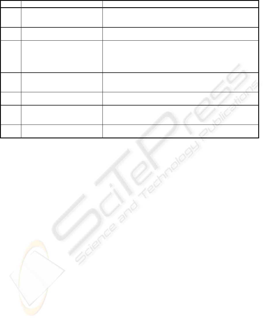
Table I: Transformation rules for RT/SA entities
rule SA/RT entities CSP+T model
1.1
1.2
Discrete data flow f of x, with
origin O and target D.
Or discrete event flow e.
(interface(proc(O)) ∪ {f ! x})∧( interface(proc(D)) ∪ {f ? x})
(interface(proc(O)) ∪ {e})∧( interface(proc(D)) ∪ {e})
2 Continuous flow f of x, with
origin O and destination D
P= proc( f )
P= f ? x → S ; S=( f ? x → S | f ! x → S)
3.1
3.2
STD defined as (Q, C, A, T, q),
∀ (q
i
, c, a, q
j
)∈ T, c ∈ C
∪
{
λ
}, a
∈ A
∪
{
λ
}
a and/or c are marker events
with marker variables m
a
, m
c
.
P= proc(q
i
) , Q= proc(q
j
)
P= c→ (a→Q) or P= a→Q, c=λ or P= c→Q, a=λ
P= c>< m
c
→ (a>< m
a
→Q) or P= a>< m
a
→Q, c=λ
or P= c>< m
c
→Q, a=λ .
4
Data storage DS with input
flows {f
i1
, ...f
in
} and output flows
{f
o1
, ...., f
om
}
P= proc(DS)
interface (P)= {f
i
,... f
in
, f
o
..., f
om
}
5 Data Transformation Process
DTP
P=proc (DTP) (a DTP can explode in additional entities).
interface (P)= interface (DTP)
6 Control Transformation Proc-
ess CTP
Q= proc (CTP)
∨
Q= proc (STD) (Q can model the STD associated to
a primitive CTP or its explosion)
interface (CTP)= Q\{alphabet (Q)-interface (CTP)}
7 E
1
, E
2
,..., E
p
, SA/RT entities in
the same scheme S
interface(S)= E
1
\{alphabet(E
1
)-interface(S)}|| E
2
\{alphabet(E
2
)-
interface(S)}|| ... E
p
\{alphabet(E
p
)-interface(S)}
ACKNOWLEDGEMENT
This work is funded by the research project
MAT2004-06872-C03-03 of the Spanish Ministry of
Science.
REFERENCES
Baressi, L., Pezzè, M., 1998. Towards Formalising Struc-
tural Analysis. ACM Transactions on Software Engi-
neering and Methodology, 7, 1, pp.80-107.
Capel, M.I., Balsas, J.R., Holgado, J.A., 2004. Systematic
Design of Real-Time Systems Based on CSP+T Proc-
ess Algebra, pp. 81-83. In 2
nd
International Workshop
on Verification and Validation of Enterprise Informa-
tion Systems, VVEIS 2004, In conjunction with ICEIS
2004. INSTICC PressSoftware
Eijk, P. H. J. van, Vissers, C. A., Diaz, M. (editors), 1989.
The formal description technique LOTOS. Elsevier
Science Publishers B.V.
Elmstrom, R., Lintualampi, R., Pezzè, M., 1993. Giving
Semantics to SA/RT by Means of High-Level Timed
Petri Nets. Journal of Real Time Systems, 5, 2/3,
pp.249-271.
Fencott, P.C., Galloway, A.J., Lockyer, M.A., O’Brien,
S.J., Pearson, S., 1994. Formalising the Semantics of
Ward-Mellor SA/RT Essential Models Using Process
Algebra, pp.681-702. In: FME’94: Industrial Benefit
of Formal Methods. LNCS 873, Springer-Verlag.
Hatley, D.J., Pirbhai, I.A., 1988. Strategies for Real-Time
Systems Specification, Dorset House, New York.
Hilderink, G.H., 2000. A Distributed Real-time Java Sys-
tem Based on CSP, pp.400-407.
In Third IEEE Inter-
national Symposium on Object-Oriented Real-Time
Distributed Computing
, ISORC 2000, Newport Beach,
California, March 15-17.
Hoare, C.A.R., 1978. Communicating Sequential Proc-
esses, Prentice-Hall, Englewood Cliffs (N.J.).
Lewerentz, C., Lindner, T., 1995. Formal Development of
Reactive Systems: Case Study Production Cell, LNCS
891, Springer-Verlag.
Semmens, L.T., Allen, P.M., 1990. Using Yourdon and Z:
An Approach to Formal Specification, pp.228-253. In:
Z-Users Workshop, Oxford, U.K., 1990.
Svensson, I., 1991. ESML: An Extended System Modeling
Language Based on the Data Flow Diagram Appendix
B, NASA Contract Report 187526.
Ward, P.T., Mellor, S., 1985. Structured Development of
Real-Time Systems, Prentice-Hall, Englewood Cliffs
N.J., USA.
Welch, P., 2001. Process Oriented Design for Java: Con-
currency for All. In Parallel and Distributed Process-
ing Techniques and Applications, PDPTA 2001, Las
Vegas, Nevada, USA.
Žic, J.J., 1994. Time-Constrained Buffer Specifications in
CSP+T and Timed CSP. ACM Transactions on Pro-
gramming Languages and Systems, 16, 6, pp.1661-
1674.
ICEIS 2005 - INFORMATION SYSTEMS ANALYSIS AND SPECIFICATION
72
