
INTEGRATING WORKFLOW EXTENSIONS INTO A
PROCESS-INTEGRATED ENVIRONMENT FOR CHEMICAL
ENGINEERING
Michalis Miatidis
1
and Matthias Jarke
1,2
1
Informatik V, RWTH Aachen, 52056 Aachen, Germany
2
Fraunhofer FIT, Schloss Birlinghoven, 53754 Sankt Augustin, Germany
Keywords:
Design Processes, Chemical Engineering, Workflow Management, Method Guidance, Process Integration.
Abstract:
Design is one of the most complex and creative tasks undertaken by chemical engineers. The early production
stages of chemical design require an adequate support because of their critical impact on the competitiveness
of the final products, as well as their environmental impact. In cooperation with researchers and industries
from the chemical engineering domain, we have created an integrated flowsheet-centered environment for the
support of the early stages of design. In order to address the global need for enterprise integration observed
in today’s highly competitive global economy, we had to make our system more aware of further organiza-
tional aspects of the executed processes. As a solution to this challenge, we integrated a number of workflow
extensions into our environment. These extensions enabled it to provide its method guidance further across
the inter- and intra-enterprise environment of our enacted processes, with the future goal of seamless inter-
operating with other external systems of the overall enterprise environment. In this paper, after capturing the
rationale behind the need for this integration, we successively describe the integrated environment and detail
the extensions employed. Finally, we illustrate our approach on a small case study from our experience.
1 INTRODUCTION
The support of chemical engineering design processes
is a very challenging task because of their creative na-
ture and critical role in the overall production. They
primarily include the original specification, simula-
tion and evaluation of several design alternatives of
a chemical product participating in a production life-
cycle. It can be argued that these early stages have a
great impact on most of the sensitive characteristics
of the whole production like the final product quality,
the cost of the overall investments and operations, as
well as the duration.
We address the demand for supporting the early
stages of design processes in chemical engineering in
the SFB 476 IMPROVE research project (Nagl and
Westfechtel, 1998). In this project, in cooperation
with chemical and plastics engineering experts, we
investigate the early phases of the polyamide6 pro-
duction, the so-called conceptual design and the ba-
sic engineering. To this end, we have developed
a process-integrated design environment that is able
to directly provide the engineers performing the de-
sign processes with situated fine-grained process sup-
port based on previous recorded experiences (Jarke
et al., 1999a). This environment is built on top of
PRIME (Process Integrated Modelling Environment)
(Pohl et al., 1999). PRIME process support is given
in the form of method guidance based on the inter-
pretation of method definitions of some well-known
parts of the processes. Through a process integration
mechanism, the behaviour of the participating tools is
automatically adjusted according to the method defi-
nitions that apply to the current situation.
The contemporary business trends are clearly to-
wards the need for a global integration, either within
a company (intra-integration) or among several enter-
prises (inter-integration) (Vernadat, 1996). In order to
keep our environment up to date with these changes
in the manufacturing world, we needed to reflect the
organizational nature of the enacted design processes
in our environment by further addressing the inter-
networking issue of the engineers provided with sup-
port throughout supply chains. In pursuit of this goal,
we have extended our initial approach with workflow
extensions that reflect the more coarse-grained enter-
prise nature of process execution.
In section 2 we detail the motivation for this inte-
gration by successively comparing the workflow man-
agement support with the method guidance and de-
scribing the integrated modelling approach that has
driven us. In section 3 we introduce our process-
integrated design environment built upon PRIME and
detail the extended metamodel adapted in pursuit of
the integration goal, and in section 4 we illustrate
our results on a small case study from the IMPROVE
255
Miatidis M. and Jarke M. (2005).
INTEGRATING WORKFLOW EXTENSIONS INTO A PROCESS-INTEGRATED ENVIRONMENT FOR CHEMICAL ENGINEERING.
In Proceedings of the Seventh Inter national Conference on Enterprise Information Systems, pages 255-260
DOI: 10.5220/0002522602550260
Copyright
c
SciTePress
project. Finally, in section 5 we provide some conclu-
sions and outlook to future work.
2 MOTIVATION
2.1 Workflow Management versus
Method Guidance
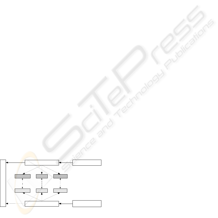
Both method guidance and workflow management
contribute to the support of processes being executed
(figure 1). Nevertheless, each one of them supports
the executed processes at a different level of granu-
larity and from a different perspective. They differ in
three main aspects:
• The primary concern of workflow management
is the process-centric automated coordination of
the interworking of human actors at the execution
level. In contrast, method guidance aims at directly
supporting the human actors performing these ac-
tivities by defining their detailed methods of work-
ing.
• The products considered by workflow management
and method guidance vary in their granularity. The
process logic of a workflow model considers the
products at the level of documents. Method guid-
ance, on the other hand, cares of the product struc-
ture of these documents as they are considered in a
more fine-grained level by the method definitions.
• Workflow activities are bound to a number of re-
sources that perform some work on behalf of them
at runtime. These resources mainly contain the par-
ticipating human actors, tools and computer sys-
tems. Since method guidance is restricted to some
activity performed by a human actor at an engineer-
ing workplace, the main resources it considers are
the involved tools.
Workflow Management
Method Guidance
Workflow Management
System
Method Guidance
Environment
provides
provides
Process Execution
supports
supports
Products
ProductsActivities Resources
Methods Tools
Figure 1: Two levels of support to process execution.
The need to provide process support and automa-
tion to the execution of business processes, has lead
to the appearance of a variety of workflow manage-
ment and method guidance standards utilized by large
enterprise information systems. The area of work-
flow management stems from the traditional area of
office automation solutions. These solutions were ori-
ented to the automation of office processes performed
by human actors. Most of the modern approaches
have been widely applied in banks, insurance com-
panies etc to manage organisational issues of routine
processes most of the times with no or little human
intervention (van der Aalst and van Hee, 2002).
In the area of method guidance we can identify the
traditional handbooks that have dominated the indus-
trial practice, to the more modern separate guidance
tools displaying to the user a list of valid method de-
finitions that apply to his given situation, e.g. (Nu-
seibeh and Finkelstein, 1992).
None of the above solutions is able to provide a
fully integrated method guidance being at the same
time aware of the enterprise coordination issues, with-
out underestimating the non-determinism of the in-
volved processes. Workflow management systems
provide technical support for the automated coor-
dination of processes that are supposed to be pre-
cisely known in advance. Most of the researchers
of this field focus on the workflow management sup-
port and the possible ways of integrating it with the
higher level of project management or enterprise re-
source planning (ERP) e.g. (Cardoso et al., 2002),
(zur Muehlen and Rosemann, 2004) but neglect the
method guidance to the human actors performing the
processes. On the other hand, the existing method
guidance techniques are concerned with short-lived
methodologies that deal with individual activities or
participants and neglect other more managerial and
organisational activities. A gap clearly exists between
the two levels of support that has not been adequately
investigated in the literature and needs to be bridged.
2.2 Integrated Modelling Approach
Workflow management supports the executed
processes based on the explicit definition of a work-
flow model capturing the process logic. On the other
hand, method guidance is specified in process models
capturing the method definitions (methodology) for
performing a task. Thus, method definitions provide
a zoomed view of workflow activities and detail the
ways of working of the human actors performing
them. Also, the products and resources are seen
as black boxes on the task level and are zoomed to
their structure on the method guidance level. The
resources are actually considered only on their tools
by the method definitions. As a consequence, we
can defined three ‘semantic bridges’ among the
interrelated elements of the two levels:
1. A mapping relationship between a workflow activ-
ity and the methods providing guidance to the en-
ICEIS 2005 - DATABASES AND INFORMATION SYSTEMS INTEGRATION
256
gineers during that activity execution.
2. An isA relationship from the products (documents)
of the workflow model to their detailed view on the
method guidance level.
3. An isA relationship from the tools belonging to the
resources of the workflow model to their detailed
descriptions on the method guidance level.
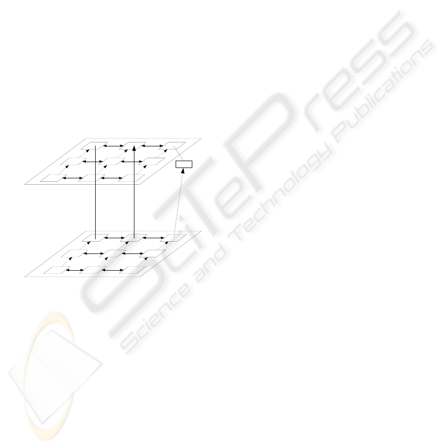
We have defined an integrated modelling approach
that is based on these semantic bridges and integrates
the interrelated concepts of the two levels of support.
In figure 2, a 3-dimensional view of this approach
is presented. The upper part represents the workflow
management level and the lower part the method guid-
ance level. On each one of them, we can identify the
contributed concepts. On the upper, we have the ac-
tivities, the products manipulated by them and the in-
volved resources. On the method guidance level, we
identify the engineering methods, the products they
change and the involved tools.
Workflow Management
Level
Method Guidance
Level
Metamodel
Model
Application
Activity
Product
Resource
Method Product
Tool
Metamodel
Model
Application
mapping isa isa
Tool
Figure 2: Integrated modelling approach.
In order to provide a generic modelling formalism
that is powerful enough to capture a wide range of
design scenarios and not restrict to just some specific
cases, we have followed the IRDS standard (ISO/IEC,
1990) and have created a three-layered hierarchy for
each level as shown in figure 2. The metamodel layer
plays the role of a generic kernel which is domain-
independent. Due to the generality of its underly-
ing concepts, it can be applied in different creative
domains of design. The model layer provides the
domain-specific knowledge of specific design scenar-
ios by instantiating the metamodel level entities. In
other words, the model layer provides a description
of the ideal world. The real world is captured on
the application layer. This layer instantiates concepts
of the model layer and captures traces of the actual
process execution. The two modelled levels are inte-
grated defining static relationships on the metamodel
level for each semantic bridge among the relevant el-
ements.
In the next section, we present the PRIME-based
design environment that has been extended accord-
ing to our integrated approach. Since PRIME was
already providing the fine-grained method guidance
support, we followed a bottom-up approach and ex-
tended its metamodel with elements from the coarse-
grained workflow management level according to the
three aforementioned semantic bridges.
3 PROCESS-INTEGRATED
DESIGN ENVIRONMENT
3.1 The PRIME-based
Flowsheet-centered Architecture
PRIME is able to provide integrated method guidance
to engineers based on the reuse of traced experiences.
The core component of PRIME is a process engine
that provides process support (automation, guidance
or enforcement) based on the interpretation of method
fragments and product object schemata, maintained in
a Process Data Warehouse (PDW) (Jarke et al., 2000).
The method guidance is provided to the user
through a process-integration mechanism (Pohl et al.,
1999) of the engineering tools. Process-integrated
tools are able to adapt their behaviour according to
the current enactment state and actual method defini-
tions (process sensitivity), provide support to the en-
gineers for direct invocation of method fragments and
return feedback information on service execution.
The capabilities of the process-integrated tools are
explicitly defined in tool models and are integrated
with process models providing the method guidance
definitions. Processes are modelled using a situation-
based contextual metamodel, initially proposed in the
NATURE project for the requirements engineering
process (Jarke et al., 1999b). A user is at any time
in a subjectively perceived situation made of a set of
states of the products undergoing the development. In
every situation, he has a given intention in his mind
and the conceptual bridge between a situation and the
valid intentions is called context. Contexts can be fur-
ther refined to executable, choice and plan contexts.
Executable contexts automate pieces of a process and
are usually realized by tool functions,choice contexts
describe the need of the engineer to make a decision
among several alternatives and plan contexts define a
systematic plan of steps that the engineer has to fol-
low. Tools are modelled with respect to their capabil-
ities (actions exposed and graphical user interface el-
ements) with a tool metamodel. The two metamodels
are integrated into the environment metamodel (lower
INTEGRATING WORKFLOW EXTENSIONS INTO A PROCESS-INTEGRATED ENVIRONMENT FOR CHEMICAL
ENGINEERING
257
part of figure 4).
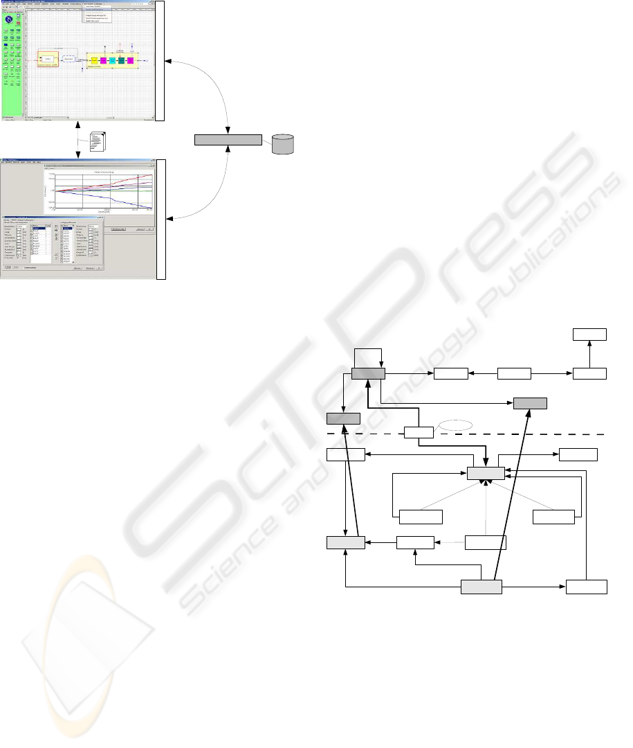
Process Engine
Flowsheet Editor
Flowsheet Editor
Process Integration Wrapper
PDW
Process Integration Wrapper
MOREX
Figure 3: Integration architecture.
We have built our integrated design environment on
top of a flowsheet-centered PRIME architecture. We
have realized a novel flowsheet editor (Bayer et al.,
2001) on the basis of the Microsoft Visio commer-
cial drawing tool. Through the process integration
mechanism, we have defined method fragments mod-
elling the basic interaction patterns of the engineers
while working on flowsheets. Some of the features
we stressed were the ability of displaying different re-
finement alternatives to the user and the simultane-
ous display of different refinement abstraction levels
in the same flowsheet view.
In order to make the data of the flowsheet acces-
sible from outside, integration with other domain-
specific tools was demanded. This exchange of infor-
mation among heterogeneous tools, is supported by
special integration tools (Becker et al., 2002) that, un-
der the supervision of the process engine, ensure data
consistency between documents. Figure 3 shows a
part of the actual integration architecture which inte-
grates the central flowsheet editor with the MOREX
(Schl
¨
uter and Haberstroh, 2002) compounding ex-
truder simulation tool. Contrary to our flowsheet ed-
itor, MOREX was loosely process-integrated as it al-
ready provides hard-coded method guidance to the
engineers and thus the process engine guidance was
limited.
3.2 Extended Metamodel
Our goal was to extend our original PRIME process
metamodel and integrate it with workflow elements
according to our aforementioned integrated modelling
approach. To this end, we adapted metamodel exten-
sions according to the Workflow Management Coali-
tion (WfMC) Standard (WfMC, 2001). WfMC has
developed specifications for standards that concen-
trate common characteristics of workflow manage-
ment products. As a result, these specifications im-
prove the opportunities for the effective integration
of commonly used workflow concepts and thus pro-
mote the interoperability with other workflow prod-
ucts. The resulting metamodel is shown in figure 4.
The existing NATURE metamodel is shown at the
lower part of the figure and is divided by a dotted line
with the adapted extensions shown at the upper part.
Following the WfMC reference metamodel, the
pieces of works that have to be done are captured in
the activity. An activity represents a logical unit of
work that requires the support of human and/or ma-
chine resources for its execution. An activity can be
arbitrary complex and be iteratively composed of oth-
ers until the basic activity level is reached. In our ex-
tended metamodel we call the activities tasks in order
to emphasize their assignment to human actors.
Task Role
asssigned to
Actor
plays
Team
member of
Enterprise
belongs to
consumes/
transforms/
produces
employs
Tool
Product
isa
isa
Mapping
Semanitcs
Context
Situation Intention
Plan
Context
Executable
Context
Choice
Context
isa
isa
isa
related situation related intention
composed of
provides alternatives of
Product
based on
applied
by
Action
changes
Tool
displays
intention of
Command
Element
provides
command element
provides
displays product
composed of
Figure 4: Extended environment metamodel.
A task provides the virtual world inside which
method guidance according to method definitions is
provided. Thus, it makes sense to create a seman-
tic mapping between tasks and NATURE-based con-
texts reflecting the methods. This mapping (first se-
mantic bridge) represents the methods that define the
legal ways of working of a human actor during the
enactment of a task. The mapping may also be carry-
ing some semantics for providing important shared
knowledge such as time scheduling information, a
partial order in the engineering contexts or even de-
fine the contexts that signal the beginning or the ter-
ICEIS 2005 - DATABASES AND INFORMATION SYSTEMS INTEGRATION
258
mination of the task execution.
While a task is being executed, it produces, con-
sumes and transforms products. The products pro-
duced by a task are characterized as output products
of the task, and the products consumed are character-
ized as input products. Input products of a task can be
either existing products from other project sessions or
output products of other predecessor tasks. On the
task level, the products are considered as documents
flowing from one task to the other. On the contextual
level, the structure of the products is detailed to allow
methods to change their properties. As a result, an
isA relationship exists among them (second semantic
bridge).
Each task requires a number of resources in order
to be carried out. Resources include primarily the hu-
man actors assigned to them, their enterprise settings
and the employed tools. Actors are indirectly associ-
ated to their assigned tasks via their roles. Roles are
distributed according to the knowledge background,
skills and assigned responsibilities of the actors play-
ing them. Actors can be divided into teams belong-
ing to enterprises, that work synergetically for the
achievement of a common goal. Since method guid-
ance is provided directly to a specific actor who is
performing a specific task at a specific workplace, the
resources considered on this level are restricted to the
involved tools. Similarly to the case of products, tools
on the method guidance level are detailed with re-
spect to their capabilities and an isA relationship is
also here deduced (third semantic bridge)
With the above metamodel extensions and the three
semantic bridges, we have managed to increase the
PRIME awareness of the more coarse-grained levels
of process execution. As a consequence, PRIME is
able to extend its method guidance mechanism for the
inter-activity support of different human actors. The
benefits of our approach are illustrated on a small case
study in the next section.
4 CASE STUDY
In this section, we detail a small example based on a
case study from the IMPROVE project that illustrates
the benefits of our approach. For the reasons of sim-
plicity and understandability, we use a small and sim-
plified fragment from our overall polyamid6 scenario.
Polyamid6 is produced from monomer chemical
plants. The design process consists of three promi-
nent process steps: reaction, separation and com-
pounding. We are going to focus on the compound-
ing phase. The compounding process modifies the
polymer in order to give it some desired characteris-
tics (such as heat resistance and mechanical stability).
Two expert roles contribute to this process: the com-
pounding expert and the 1D-simulation expert. The
main task of the compounding expert, is the concep-
tual configuration of the compounding extruder in-
side the process-integrated flowsheet editor. The re-
sulting configuration is further analyzed by the 1D-
simulation expert who simulates the compounding ex-
truder configuration based on physical and mathemat-
ical models.
Because of the integrated workflow extensions,
PRIME is able to further apply coordination and
method guidance outside of the frontiers of a specific
task. Process engine is aware of the interconnected
tasks and through the semantics of the mapping of
contexts to activities, contexts signaling the beginning
or the termination of a task can be known. Thus, in
the case of a need of control and data flow among two
activities, the terminating context of the first task, can
be coupled with the beginning context of the second
through a plan context and the data transfer can be
realized under the support of the process engine.
Export to MOREX
Export Extruder
Configuration
Import Extruder
Configuration
(plan context)
(executable context)
(executable context)
extruder configuration
composed of
mapped to
mapped to
mapped to
Design of
Compounding Elements
1D-Simulation of
Compounding Process
Compounding Expert
d
i
s
p
l
a
y
o
f
i
n
t
e
n
t
i
o
n
1D-Simulation Expert
Flowsheet Editor
MOREX
Figure 5: Example of inter-activity method guidance.
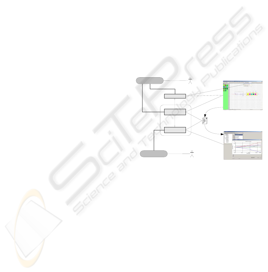
Figure 5 shows a UML-like diagram of the transi-
tion from the ‘Design of Compounding Elements’ task
of the compounding expert to the ‘1D-Simulation of
Compounding Process’ task of the 1D-simulation ex-
pert. The compounding expert is invoking the ‘Ex-
port to MOREX’ plan context through a menu item
in the flowsheet editor. This plan context defines the
strategy (steps) for the transition. The first step is
the executable context ‘Export Extruder Configura-
tion’, applied automatically by a flowsheet editor ac-
tion, that exports the extruder configuration to XML
format. The next step is the ‘Import Extruder Con-
figuration’ executable context applied by a MOREX
action in the workplace of the 1D-simulation role. It
receives the exported extruder configuration and im-
ports it in MOREX creating a new project configura-
tion. Now the expert can modify the properties of the
received extruder if needed and start the simulation.
INTEGRATING WORKFLOW EXTENSIONS INTO A PROCESS-INTEGRATED ENVIRONMENT FOR CHEMICAL
ENGINEERING
259

5 CONCLUSIONS AND
OUTLOOK
In this paper we presented the extensions applied to
a PRIME-based environment for supporting chemical
engineering design processes. Initially this environ-
ment was capable of providing intra-activity situated
method guidance i.e. at a specific engineering work-
place. Motivated by the integration trends in modern
enterprises, we developed a modelling approach ex-
tending our existing fine-grained process models and
integrating it with the more coarse-grained level of
workflow activities. This integration was achieved us-
ing the three introduced semantic bridges. As a con-
sequence, the gap between the workflow management
level and the method guidance level was narrowed. A
better understanding of the full granularity spectrum
of the executed processes was achieved and our en-
vironment was able to further provide inter-activity
method guidance to various engineers.
Our adapted integrated modelling approach, con-
centrates two viewpoints on our executed processes.
On the method guidance level, our contextual process
model captures method fragments and thus views
processes ‘in the small’. On the workflow manage-
ment level, on the other hand, a broader view is taken
decomposing processes to well-defined tasks. In the
near future, we are planning to investigate ways of
further capturing inside our underlying models the
intermediate level of methods as assemblies of our
stored method fragments (Ralyt
´
e and Rolland, 2001).
Further future work is planned to address the area
of interoperability of our integrated environment with
other external components of the IMPROVE inte-
grated design environment. In particular, we are in-
terested to integrate our fine-grained method guid-
ance environment with the AHEAD reactive adminis-
tration system developed for the coarse-grained man-
agement of design processes (Westfechtel, 2001).
Our main goal is to enable AHEAD to directly
call the PRIME process engine services such as di-
rect manager-triggered invocations of specific process
fragments and to get back notifications concerning the
execution status of activities.
ACKNOWLEDGEMENTS
This work was carried out in the Collaborative Re-
search Center 476 IMPROVE which is funded by
the Deutsche Forschnungsgemeinschaft (DFG). We
would like to thank Christoph Quix, Sebastian Brandt
and Marcus Schl
¨
uter for their valuable contributions
to our work.
REFERENCES
Bayer, B., Marquardt, W., Weidenhaupt, K., and Jarke, M.
(2001). A flowsheet centered architecture for concep-
tual design. In ESCAPE-11.
Becker, S., Haase, T., Westfechtel, B., and Wilhelms, J.
(2002). Integration tools supporting cooperative de-
velopment processes in chemical engineering. In Intl.
Conf. Integrated Design and Process Technology.
Cardoso, J., Bostrom, R. P., and Sheth, A. (2002). Work-
flow management systems vs. ERP systems: Differ-
ences, commonalities, and applications. Technical re-
port, University of Georgia.
ISO/IEC (1990). Information technology - information
resource dictionary systems (IRDS) - framework.
ISO/IEC international standard.
Jarke, M., List, T., and K
¨
oller, J. (2000). The challenge of
process data warehousing. In 26th Intl. Conf. on Very
Large Databases, pages 473–483.
Jarke, M., List, T., and Weidenhaupt, K. (1999a). A
process-integrated conceptual design environment for
chemical engineering. In ER, pages 520–537.
Jarke, M., Rolland, C., Sutcliffe, A., and D
¨
omges, R., ed-
itors (1999b). The NATURE of Requirements Engi-
neering. Shaker Verlag.
Nagl, M. and Westfechtel, B., editors (1998). Integration
von Entwicklungssystemen in Ingenieuranwendungen.
Springer-Verlag.
Nuseibeh, B. and Finkelstein, A. (1992). Viewpoints: A
vehicle for method and tool integration. In 5th Inter-
national Workshop on Computer-Aided Software En-
gineering.
Pohl, K., Weidenhaupt, K., D
¨
omges, R., Haumer, P., Jarke,
M., and Klamma, R. (1999). PRIME - toward process-
integrated modeling environments. ACM Trans. Softw.
Eng. Methodol., 8(4):343–410.
Ralyt
´
e, J. and Rolland, C. (2001). An assembly process
model for method engineering. In 13th International
Conference on Advanced Information Systems Engi-
neering.
Schl
¨
uter, M. and Haberstroh, E. (2002). Design of twin
screw extruders with the MOREX simulation soft-
ware. In PPS.
van der Aalst, W. and van Hee, K. (2002). Workflow Man-
agement. The MIT Press.
Vernadat, F. B. (1996). Enterprise Modeling and Integra-
tion - Principles and Applications. Chapman and Hall.
Westfechtel, B. (2001). AHEAD: A graph-based system
for modelling and managing development processes.
Informatik Forsch. Entw., 16(3):125–144.
WfMC (2001). The Workflow Management Coalition Spec-
ification (http://www.wfmc.org).
zur Muehlen, M. and Rosemann, M. (2004). Multi-
paradigm process management. In Proceedings of
CAiSE’04 Workshops - 5th Workshop on Business
Process Modeling, Development and Support.
ICEIS 2005 - DATABASES AND INFORMATION SYSTEMS INTEGRATION
260
