
RELIABLE MULTICAST PROTOCOL
A modified retransmission-based loss-recovery scheme based on the selective
repeated ARQ protocols
Chih-Shing Tau, Tzone-I Wang
National Cheng Kung University, No. 1, Ta-Shueh Road, Tainan City, Taiwan, R.O.C.
Keywords: Loss-recovery, Reliable multicast protocol, Retransmission
Abstract: This paper proposes a modified retransmission-based loss-recovery mechanism based on the selective
repeated ARQ protocols for reliable multicast delivery. With the operation of XOR, it minimizes the
number of packets for retransmissions, reduces the network burden, and increases the throughput.
Furthermore, the analysis infers a basis for choosing the suitable loss-packed size of retransmission to
achieve higher throughput with lower network cost. The delays of processing time are also evaluated as
well. Some interested effects of key system parameters on the delay performance are observed.
1 INTRODUCTION
IP multicast is an Internet Engineering Task Force
(IETF) standard that allows a single packet to be
sent to a potentially large number of receivers.
Despite its unreliability, it is both selective (each
packet is delivered only to receivers who have
subscribed to the multicast address) and efficient
(a packet is never transmitted on a link more than
once). However, most applications such as
video-conferencing, distributed interactive
simulation, and news distribution still require
some form of reliability to recover themselves
from link-level packet losses even though the
packet losses are an inherent by-product of
Internet congestion control (Whetten, 1998).
In data communication, one of the most widely
used techniques for handling transmission errors at
the data link layer is error detection with
Automatic-Repeat-reQuest (ARQ). This scheme is
simple and highly reliable. The protocol is usually
classified into three basic categories: Selective
repeat, Go-back-N, and Stop-and-wait. Many
researches have analyzed these basic protocols
((Benice, 1964), (Bruneel, 1986), (Burton, 1972))
and thoroughly studied the variants to the three
basic protocols ((Towsley, 1987), (Weldon, 1982)).
One principle feature those variants share is to
send multiple copies of each loss packet instead of
just one copy of each loss packet, which makes
heavier the network burden. This paper showcases
an improved recovery retransmission mechanism
to decrease significantly this kind of network
burden. It is based on (a) automatic-repeat-request
protocols to enhance the capacity of a
communication channel and (b) the idea of
XORing several combined retransmitted packets
to minimize the number of retransmissions and to
hence increase the throughput.
Section 2 describes the Loss-Recovery
Retransmission Scheme equipped in the protocol.
Several analyses for the Pure SR and
Loss-Recovery Retransmission protocols are
discussed in Section 3. Finally, concluding
remarks are given in Section IV.
2 LOSS-RECOVERY
RETRANSMISSION SCHEME
2.1 System Scenario Description
The scenario considered in this paper consists of
one sender and m receivers, where the
communication between the sender and receivers
takes place over multicast channel. The data
packets transmitted by the sender can be received
by all the m receivers. Once a packet is lost, a
receiver will send back a negative
acknowledgement (NACK) to the sender. Data
messages are sent as fixed length data block.
310
Tau C. and Wang T. (2005).
RELIABLE MULTICAST PROTOCOL - A modified retransmission-based loss-recovery scheme based on the selective repeated ARQ protocols.
In Proceedings of the Second International Conference on e-Business and Telecommunication Networks, pages 310-317
DOI: 10.5220/0001412803100317
Copyright
c
SciTePress
Assume that the lost packets at all receivers for
all transmissions are independent and that the
probability of packet loss, p, is the same among all
channels. Furthermore, NACKs and retransmitted
packets are never lost.
The assumption that losses among receivers
occur independently still holds when the multicast
backbone loss is small (observed experimentally
in the MBone in (Yajnik, 1996)) and when there is
low loss from the sender into the backbone. It is
possible that losses could correlate, according to
the concept of association of random variables
(Esary, 1967). The pessimistic bounds on
throughput resulted from our analyses are hence
regarded as a consequence of this independence
assumption. Another assumption that NACKs is
never lost is reasonable as control packets are
small. If necessary, the assumption can be relaxed
by following the analysis given in (Towsley,
1985).
In this context, we now describe the two
approaches, pure selective repeat (Pure SR) and
loss-recovery retransmission strategies, for
reliable transmission of the data packet from
sender to multiple receivers.
Pure selective repeat strategy is a
receiver-initiated protocol that assigns the
responsibility for ensuring reliable packet delivery
to the receivers, whose role is to check for the lost
packets. That is, sender keeps transmitting new
data packets until it receives a NACK from a
receiver. When this occurs, the sender then
retransmits (i.e. again multicasts) the lost packet to
all its receivers. In order to guard against the loss
of the NACK and the subsequent packet
retransmission, the receiver use timers in a manner
analogous to the sender’s use of timers in
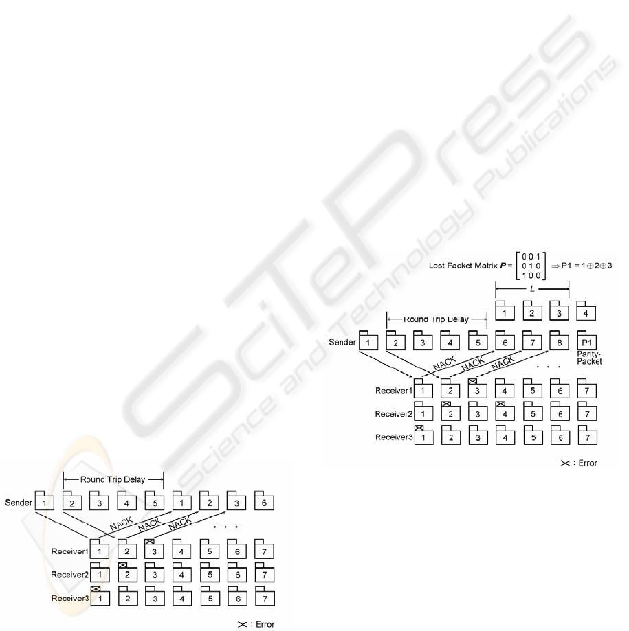
sender-initiated protocols (Towsley, 1997). Figure
1 illustrates an example of pure selective repeat
strategy.
Fiqure 1: Pure selective repeat strategy.
With loss-recovery retransmission, the sender
does not retransmit requested packet upon
receiving a NACK. Rather, it gathers NACKs to a
certain number L (L
≥ 1) after a period of the
round trip propagation delay, and then decides and
groups among these unacknowledged packets into
so-called a parity-packet. Of course, each receiver
must be able to reconstruct all its lost packets from
parity-packet; namely it must recognize all the
packets included in the parity-packet. With the
XOR operation conducting on all the packets,
correctly received and parity-packet, the receiver
obtains the expected lost packet.
Figure 2 illustrates an example of
loss-recovery retransmission strategy. Each NACK
represents a negative acknowledgement reported
by at least one of the receivers. The size of L is 3
packets. The sender sums the NACKed packets 1,
2, and 3 by elementary modulo 2 addition (XOR)
into a parity-packet and retransmits these 3
NACKed packets in this parity-packet instead of
retransmitting them separately. After error-free
reception of the parity-packet, each receiver
checks the header in order to identify the sequence
numbers of data packets in the parity-packet. With
the help of the sequence numbers it can
reconstruct the expected packet from the
parity-packet as described below.
Figure 2: Loss-recovery retransmission strategy.
The difficulty of this Loss-Recovery
Retransmission strategy lies in combining as many
NACKed packets in a parity-packet as possible
and also ensuring that each related receiver can
recognize its lost packets from the parity-packet in
no time.
2.2 Loss-Recovery Retransmission
Mechanism
To analyze this strategy, we have to describe
mathematically which receiver needs the
RELIABLE MULTICAST PROTOCOL - A modified retransmission-based loss-recovery scheme based on the selective
repeated ARQ protocols
311

retransmission of what packets in advance. We use
P to denote a lost packet matrix, which is
generated after the arrival of a certain number of
NACKs, L, at sender’s site, with the receiver
numbers as rows and packet numbers as columns.
If receiver i has lost packet j, the matrix element at
position (i, j) is set to one; otherwise, the element
is set to zero. The lost packet matrix P is shown
below:
Packet1 Packet2 Packet3
Receiver1 0 0 1
Receiver2 0 1 0
Receiver3 1 0 0
Algebraically, the above matrix consists of
column vectors:
⎥
⎥
⎦
⎤
⎢
⎢
⎣
⎡
1
0
0
,
⎥
⎥
⎦
⎤
⎢
⎢
⎣
⎡
0
1
0
, and
⎥
⎥
⎦
⎤
⎢
⎢
⎣
⎡
0
0
1
. Assume
that there is a
m by n matrix P. Then we denote n
column vectors as
P
1
, P
2
, …, P
n
. If they are all
orthogonal, namely, no receiver has lost more than
one packet, the sender can exclusive-or all these
n
packets to obtain a single recovery packet,
parity-packet. To prove the two vector’s
orthogonality, we use inner product.
A = (a
1
, a
2
, …, a
n
) and B = (b
1
, b
2
, …, b
n
) are
orthogonal if
a
1
b
1
+ a
2
b
2
+ … + a
n
b
n
= 0.
We can see that if each retransmission request
comes from different receiver, the Loss-Recovery
Retransmission mechanism will work very well.
Yet once such situation disappears and no
modification is given, the reliability will not be
guaranteed. For example, in case Receiver2 also
loses Packet3, each column vector of the matrix
P
goes like
⎥
⎥
⎦
⎤
⎢
⎢
⎣
⎡
1
0
0
,
⎥
⎥
⎦
⎤
⎢
⎢
⎣
⎡
0
1
0
, and
⎥
⎥
⎦
⎤
⎢
⎢
⎣
⎡
0
1
1
. If the
parity-packet is made up of
Packet3Packet2Packet1 ⊕⊕ , Receiver2 may not
be able to reconstruct Packet2 and Packet3, as
efficiently as both Receiver1 and Receiver3.
Notice that, columns
P
1
and P
2
are orthogonal,
so are columns
P
1
and P
3
. If sender sets one
parity-packet as
Packet2Packet1⊕
or
Packet3Packet1⊕ , and treats the remaining
packet (Packet3 or Packet2) as another
parity-packet, Loss-Recovery Retransmission
strategy still works well because every two
column vectors in the packet are orthogonal.
To make good use of Loss-Recovery
Retransmission mechanism, we should find as
many orthogonal column vectors as possible from
matrix
P, which forms a submatrix of P, denoted
as
P′. This set of packets that are to be XORed for
an arbitrary error pattern
1
can be pre-computed
and stored in tables to avoid high computational
cost during transmission. The algorithm of finding
out
P′ is shown in next subsection.
2.3 Algorithm of Building a Matrix
P′
In (Aghadavoodi Jolfaei, 1993), Aghadavoodi
Jolfaei et al interpret lost packet matrix
P as the
incidence matrix of a hypergraph (Berge, 1989).
By that the problem of generating parity-packets
from a given error matrix was linked with the edge
coloring problem of graph theory (Aghadavoodi
Jolfaei, 1993). In this subsection, we present a
simple straightforward algorithm of finding out
submatrix
P′.
Provided that sender has already achieved the
lost packet matrix
P, which is m by n. Recall that
m stands for the number of receiver which submits
retransmission request, and correspondingly
n
stands for the number of packet which is lost at the
receiver site. In this system scenario, any receiver
might lose more than two packets, and any packet
might be lost by two or more receivers. We can
rewrite matrix
P as [P
1
, P
2
, …, P
n
] (P
i
is a m × 1
column vector). The algorithm is shown as
follows:
Algorithm 1.
Step 1: Get an arbitrary element from P and
add it to submatrix
P′.
Step 2: Check a vector P, not in P′, which is
orthogonal with every element of
P′,
add
P to the P′, and at same time delete P
in
the matrix
P.
Step 3: Repeat Step 2 until no remaining
vector
P is orthogonal with every element of
P′
or
P is empty.
Step 4: If P is not empty, then back to Step 1 to
find another submatrix
P′ and repeat
Step
1
The task to determine a minimum subset is
presumably NP-complete [7]. Nevertheless an exact
calculation is possible if the number of packets per
parity-packet is limited.
ICETE 2005 - SECURITY AND RELIABILITY IN INFORMATION SYSTEMS AND NETWORKS
312

2 ~ 3.
Step 5: Repeat Step 1 ~ 3 until P is emptied.
Step 6: Output all the submatrice P′.
3 ANALYTICAL RESULTS
3.1 Expected Number of NACKs
Received by the Sender
For an analysis of the transmission cost, the
following three parameters are needed:
m = number of receivers,
h = number of hops between sender and
receivers,
p = packet loss probability per hop.
Assume that
h is constant and p is equal among
all links. Let
p
b
denote the probability that a
packet is lost on a link branch in the multicast tree
from the sender to a receiver. Then
p
b
can be
expressed as
p
b
= 1 – ( 1 – p )
h
. (1)
Let the random variable
X denote the number
of retransmissions by the sender necessary for all
m receivers to successfully receive a packet and X
r
is the number of transmissions required for
receiver
r to receive the lost packet correctly, i.e.
}1 ; max{ mrXX
r
≤≤= . The number of NACKs
reported to the sender by receiver
r is X
r
– 1.
Hence, the mean number of NACKs received by
the sender from the receiver
r is
∑
∞
=
−
−−=−
2
b
1
b
)1()1()1(
k
k
r
ppkXE
=
b
b
1 p
p
−
(2)
Consequently, the expected number of NACKs
received by the sender from all the receivers is
mp
b
/(1 – p
b
).
Assuming all retransmissions are to be
performed by the sender and loss events
independent for each receiver the following
probabilities for
X can be derived (cf. D. Towsley
et al (Towsley, 1997)):
)()(
1
nXPnXP
r
m
r
≤=≤
∏
=
=
in
i
m
i
p
i
m
b
0
)1( −
⎟
⎠
⎞
⎜
⎝
⎛
∑
=
, (3)
where
n is positive integer and thus
)1()()( −≤
−
≤
=
=
nXPnXPnXP
=
)1()1(
bb
0
iin
i
m
i
pp
i
m
−
=
−−
⎟
⎠
⎞
⎜
⎝
⎛
∑
. (4)
The expected number of retransmissions is
[]
∑
∞
=
==
1
)()(
k
kXkPXE
=
)1(
1
)1(
b
1
1
i
i
m
i
p
i
m
−
−
⎟
⎠
⎞
⎜
⎝
⎛
+
=
∑
. (5)
If the sender has to send D packets, the sender
should expect to receive D⋅E(X) NACKed packets
statistically.
3.2 Expected Number of
Parity-Packets Sent by the
Sender
For further analysis, let the random variable Y
denote the number of parity-packet generated for a
L loss-recovery retransmissions. If
P = [P
1
, P
2
, …,
P
n
], Y is exactly the minimum number of the
submatrices, within which each two vectors are
orthogonal. Therefore, the retransmitted
parity-packet RP is
)(
)(
YE
L
XED
RP ⋅
⋅
=
. (6)
Apparently, Equation (6) fails to offer a
general way to determine E(Y) as this value
depends greatly on the packet loss rate as well as
the number or receivers, total packets, and the size
of loss-recovery retransmissions. Viewing from
different perspective, it might be necessary to find
another way out. We assume now for this analysis
that
M
)(
L
YE =
where M
≥
1 (M is the mean
number of packets in a parity-packet). This
assumption leads to
M
)(XED
RP
⋅
= . (7)
Ideally, every NACK within on collected
window asks for distinct packet, thus
M = L and
L
XED
RP
)(
⋅
= . (8)
However, it can not be guaranteed throughout
the whole multicast communication. The worst
case is when every two vectors are not orthogonal,
M = 1, and
)(XEDRP
⋅
=
. (9)
It is hence degenerated into a Pure SR
(Selective Repeat) strategy, which is the worst
case of all.
RELIABLE MULTICAST PROTOCOL - A modified retransmission-based loss-recovery scheme based on the selective
repeated ARQ protocols
313

Figure 3 gives the differences between various
numbers of receivers with each curve indicating
how number of retransmitted packets change
along with mean number of packets in a
parity-packet.
The retransmitted packet number has inverse
ratio relationship with M, mean number of packets
in a parity-packet. The trends indicate while M is
5 ~ 10 there appears a good expected value of the
retransmitted packets; whereas while M > 10, the
throughput receives marginal effect. We infer from
this finding a basis for choosing a suitable size of
L, size of collected window, for network
communication with various situations.
0 5 10 15 20
0
200
400
600
800
1000
1200
Mean number of packets in a parity-packet
Numbe
r
of
r
et
r
ansmitted packets
m = 10
m = 50
m = 100
m = 500
m = 1000
m = 5000
m = 10000
( p
b
= 0.005, D = 1000 )
Pure SR
Figure 3: Comparison of the retransmitted packet as a
function of M between Pure SR and Loss-Collected
Retransmission strategy for various receivers m
3.3 Delay Evaluation
This paper presents an improved method to
recover lost packets in multicast applications. The
source is the only network node able to retransmit
lost packets (global recovery mechanism) and, to
decrease the amount of retransmissions (and hence,
network congestion), several lost packets are
assembled in a single packet (parity-packet) before
retransmission. However, the delay by waiting for
several lost packets to be assembled into a single
retransmission packet might be significant.
Our goal in analyzing both the sender and
receivers will be to compute the necessary amount
of processing time (at both the sender and a
receiver) for a packet to be successfully delivered
from the sender to all of the receivers. The
processing time includes the amount of time
needed to send/receive the original packet as well
as any retransmissions of that packet, and the
amount of time needed to send/receive NACK
packet. These delay measures will be of our
primary interest in this subsection.
We begin by considering the transmission of a
packet from one participant, henceforth referred to
as the sender, to m identical participants,
henceforth referred to as receivers. As the
behavior of the sender differs from that of a
receiver, we consider their behaviors separately.
We now analyze the Pure SR protocol first by
considering the sender. Let
SR
sender
T denote the
packet processing time required at the sender
under Pure SR protocol. This processing time can
be expressed as
∑∑
==
+=
R
i
NACK
X
k
t
iTkTT
s
11
SR
sender
)()( , (10)
where the first term corresponds to the processing
time associated with the X different transmissions
of the packet and the second term corresponds to
the processing time for the NACKs that are
transmitted from the receivers to the sender.
{
)(kT
t
} and { )(iT
s
NACK
} are sequences of
identically distributed random variables. As before,
X is the number of transmissions required and R is
the number of NACKs received.
The mean processing time is given as
)()()()()(
SR
sender
s
NACKt
TERETEXETE +=
. (11)
The number of NACKs reported to the sender
by receiver r is X
r
– 1 with mean p
b
/(1 – p
b
).
Hence the mean number of NACKs reported by all
receivers is E(R) = mp
b
/(1 – p
b
), the mean per
packet processing time at the sender is
b
b
SR
sender
1
)(
)()()(
p
TEmp
TEXETE
s
NACK
t
−
+=
. (12)
We focus next on the mean per packet
processing time at a receiver. In a similar fashion,
the mean processing time required at the receiver
for a randomly chosen packet is
+−= )()1)(()(
b
SR
receiver p
TEpXETE
(
)
+−
+
)()1(
r
NACKr
TEXE
(
)
)()2(
toutr
TEXE
+
− , (13)
where
},0max{)X( x=
+
.
p
T
,
r
NACK
T
, and
tout
T are times to receive a packet, NACK
transmission times, and times to process timeout at
receiver respectively.
Here the first term corresponds to the
processing required to receive a packet. The
second term corresponds to the processing
ICETE 2005 - SECURITY AND RELIABILITY IN INFORMATION SYSTEMS AND NETWORKS
314

required to prepare and return NACKs. Note that
this only occurs each time the receiver determines
the packet to be lost prior to the first correct
receipt of this packet. The last term corresponds to
the processing of the timer when it expires. Again,
this is only required after the first transmission (if
lost) up to, but not including, the first correct
reception of a given packet.
From the distribution of X
r
, it follows that
()
b
b
1
)1(
p
p
XE
r
−
=−
+
,
()
)1()2()2(
b
1
b
3
ppkXE
k
k
r
−−=−
−
∞
=
+
∑
=
b
2
b
1 p
p
−
. (14)
Substituting into Equation (13) gives
+−= )()1)(()(
b
SR
receiver p
TEpXETE
.
1
)(
1
)(
b
2
b
b
b
p
TEp
p
TEp
tout
NACK
r
−
+
−
(15)
We end up this subsection with the analysis of
the Loss-Recovery Retransmission strategy.
Loss-Recovery Retransmission Strategy differs
from Pure SR in that the sender does not
retransmit requested packets immediately upon
receiving a NACK. Instead gathers L (L
≥ 1)
numbers of NACKs after the period of the round
trip propagation delay, and then groups among
these unacknowledged packets into several
so-called parity-packets. This delay is
∑∑
==
+
L
i
c
L
k
t
iTkT
00
)()( , where { )(iT
c
} is the sequence
of identically distributed random variable which
corresponds to the time to process parity-packet.
Let
LR
sender
T
denote the packet processing time
required at the sender under Loss-Collected
Retransmission protocol. The mean processing
time can be expressed as
)()()()(
LR
sender
s
NACKct
TERETTETE ++=
=
++−
∑
=
−
)()()1(
0
bb ct
L
i
iL
i
TETEpp
)()(
s
NACK
TERE
. (16)
The mean number of NACKs returned by all
receivers is E(R) = mp
b
/(1 – p
b
) and the mean time
of parity-packet process, E(T
c
), by the sender is
pp
L
k
c
Tk
L
TE
∑
=
=
1
1
)(
=
pp
T
L
2
1
+
, (17)
where
pp
T is the time to generate a parity-packet.
Substituting into Equation (16) gives
+−=
∑
=
−
)()1()(
0
bb
LR
sender
t
L
i
iL
i
TEppTE
)(
12
1
b
b
s
NACKpp
TE
p
mp
T
L
−
+
+
. (18)
Similar to the analysis of Equation (18), we
have the mean processing time at the receiver
under Loss-Recovery Retransmission protocol,
)(
LR
receiver
TE , which can be expressed as
+−= )()1)(()(
b
LR
receiver p
TEpXETE
(
)
+−
+
)()1(
r
NACKr
TEXE
)(
dp
TTE
+
, (19)
d
T , similar as
c
T , is the time for a receiver to
recover the lost packet.
Hence, the mean processing time required at
the receiver for a randomly chosen packet is
+−= )()1)(()(
b
LR
receiver p
TEpXETE
+
−
)(
1
b
b
r
NACK
TE
p
p
+−
∑
=
−
)()1(
0
bb
p
L
i
iL
i
TEpp
pp
T
L
2
1
+
. (20)
0 2000 4000 6000 8000 10000
Receivers
0
1
2
3
4
Mean Delay (s)
Pure SR
Loss-Recovery Retransmission
P
b
= 0.25
P
b
= 0.10
P
b
= 0.05
P
b
=0.01
P
b
= 0.25
P
b
= 0.10
Figure 4: Mean processing time delayed at the sender
for Pure SR and Loss-Recovery Transmission Protocols.
RELIABLE MULTICAST PROTOCOL - A modified retransmission-based loss-recovery scheme based on the selective
repeated ARQ protocols
315

0 2000 4000 6000 8000 10000
Recevers
0
1
2
3
4
5
6
7
Mean Delay (ms)
Pure SR
Loss-Recovery Retransmission
P
b
= 0.01
P
b
= 0.01
P
b
= 0.05
P
b
= 0.05
P
b
= 0.10
P
b
= 0.10
P
b
= 0.25
P
b
= 0.25
Figure 5: Mean processing time delayed at the receiver
for Pure SR and Loss-Recovery Transmission Protocols.
Figure 4 and Figure 5 show the mean values of
processing time delayed at the sender and receiver
for Pure SR Protocol and Loss-Recovery
Retransmission Protocol. In our numerical
examples we have
s 1000)()(
µ
=
=
pt
TETE for
the processing time needed to send or receive a 2K
data packet and
s 500)()(
µ
==
rs
NACKNACK
TETE
as the
processing time to send or receive a small NACK
packet (Kay, 1993). We use
s 24)(
µ
=
tout
TE
(Kay(1), 1993) to indicate the timer overhead and
s 1002KBs 5.6
µ
≅×= nT
pp
the time to generate
a parity-packet. We examine such delay for loss
probabilities in the range 0.01 – 0.25 as they
typify the loss characteristics of the MBone
(Yajnik, 1996).
4 CONCLUSIONS
By fully reliable we mean that the protocol should
provide recovery from losses even at the expense
of reduction of throughput. Rather, at the end of
transmission, the sender has to guarantee that
every receiver in its membership set has received
all the data packets it transmitted. In this paper we
have discussed an improved retransmission-based
approach to packet loss recovery schemes for
multicast communication protocol, the
Loss-Recovery Retransmission strategy. In this
strategy the sender does not retransmit requested
packets immediately upon receiving of a NACK;
instead, it gathers a number of selected NACKed
packets by XORing them to minimize the number
for retransmissions and thus actually reduces the
network burden and increases the throughput. The
analytical results for a Pure SR strategy show the
decrease in retransmission of the Loss-Recovery
Retransmission strategy with the growing mean
number of packets in a parity-packet, packet loss
rate, and the quantity of the participating receivers.
Furthermore, one significance in our analysis of
this strategy is that we can estimate a suitable
collected window size of the loss-recovery
retransmission for the present various network
characteristics.
We also analyze both the sender and receiver
and evaluate the expected amount of processing
time required by Pure SR and Loss-Recovery
Retransmission protocols for a packet to be
successfully delivered from the sender to all of the
receivers.
REFERENCES
Aghadavoodi Jolfaei, M., Martin, S.C., and Mattfeldt, J.,
1993. A new efficient selective repeat protocol for
point-to-multipoint communication. In IEEE Proc.
ICC’93. IEEE Press.
Berge, C., 1989. Hypergraphs. Amsterdam:
North-Holland.
Benice, R.J. and Frey, Jr. A.H., 1964. An analysis of
retransmission system. In IEEE Trans. Comm. Tech..
IEEE Press.
Bruneel, H. and Moeneclaey, M., 1986. On the
throughput performance of some continuous ARQ
strategies with repeated transmission. In IEEE
Trans., Comm.. IEEE Press.
Burton, H.O. and Sullivan, D.D., 1972. Errors and error
control. In Proceeding IEEE. IEEE Press.
Esary, J.D., Proschan, F., and Walkup, D.W., 1967.
Association of random variables with applications.
In Ann. Math. Stat.
Hoyer, I., 1981. The NP-completeness of the
edge-coloring. In SIAM J. Comput.
Kay, J. and Pasquale, J., 1993. Measurement, analysis,
and improvement of UDP/IP throughtput for the
DECstation 5000. In Proceeding 1993 Winter
Usenix Conference.
Kay(1), J. and Pasquale, J., 1993. The importance of
nondata touching processing overhead in TCP/IP. In
Proceeding ACM SIGCOMM ’93. ACM Press.
Towsley, D., Kurrose, J., and Pingali, S., 1997. A
comparison of sender-initiated and receiver-initiated
reliable multicast protocols. In IEEE Journal on
Selected Area in Comm.
Towsley, D. and Mithal., S., 1987. A selective repeat
ARQ protocol for a point to multipoint channel. In
Proceeding INFOCOM.
ICETE 2005 - SECURITY AND RELIABILITY IN INFORMATION SYSTEMS AND NETWORKS
316

Towsley, D., 1985. An analysis of a point-to-multipoint
channel using a go-back-N error control protocol. In
IEEE Trans. Comm..
Weldon, E.J., 1982. An improved selective-repeat ARQ
strategy. In IEEE Trans. Comm..
Whetten, B. and Conlan, J., 1998. A rate based
congestion control scheme for reliable multicast.
GlobalCast Commun. Tech. White Paper.
Yajnik, M., Kurose, J., and Towsley, D., 1996. Packet
loss correlation in the mbone multicast network. In
IEEE Global Internet Conf. IEEE Press.
RELIABLE MULTICAST PROTOCOL - A modified retransmission-based loss-recovery scheme based on the selective
repeated ARQ protocols
317
