
AUTOMATED CONFIGURATION DISTRIBUTION IN VERINEC
∗
David Buchmann, Dominik Jungo, Ulrich Ultes-Nitsche
University of Fribourg
Chemin du Mus
´
ee 3, 1700 Fribourg, Switzerland
Keywords:
Network management, generated configuration, runtime verification, XML network specification.
Abstract:
We present in this paper a system to configure networks. The Verified Network Configuration (Verinec) project
aims to manage the complete network from one central XML database. This approach allows to test whether
the configuration is usable prior to modify the setup of the real network devices.
The distribution of the configuration is handled by the adaption module, a framework which can be extended
to support all kinds of services and devices. Applying the configuration to each managed device within the
network requires conversion from the Verinec XML database into a format suitable for that device and send the
configuration to the device using a protocol supported by that device. In this paper, we focus on the adaption
module.
1 INTRODUCTION
Administrating a network gets more and more dif-
ficult with increasing size of the network. Besides
routers and switches, one finds different servers and
finally workstations that need to be configured. All
configuration should be consistent for the network to
run smoothly. Moreover, each managed device comes
with its own administration tool. Configuring every
machine on the network manually is error prone and
makes it hard to maintain an accurate documentation
of the network.
With the Verinec project (Ultes-Nitsche et al.,
2005), we aim to build a solution for centrally ad-
ministrating large heterogeneous networks. Having
a central administration tool is not merely a conve-
nience for the administrator, but can be used to ensure
a consistent setup. This will augment both reliability
and security of the network.
1.1 Verinec Overview
Verinec is based on a central network definition that is
independent of the products currently used. Our inter-
nal representation is expressed in XML. Every man-
ageable networking element is uniformly considered
∗
The VeriNeC project (Ultes-Nitsche et al., 2005) is
funded by the Swiss National Science Foundation.
as a node, for example a router or a server computer
providing several services. Several modules are built
around this language.
There is a module to define the network. It con-
tains an editor to create and configure nodes and the
network layout. However, in many cases, the network
already exists. Thus we built a sniffer module that
analyses the network traffic to detect nodes. For this
purpose, we use JPCap (Charles, 2005). Then we use
the portscanner Nmap (Fyodor, 2005) to detect ser-
vices running on the found hosts. With the results of
the port scan and an administrator providing the nec-
essary authentication details, the analysis of hosts can
continue. Verinec can parse configuration files or use
the Simple Network Management Protocol (SNMP)
to determine the exact configuration of the services
detected with Nmap. Finally, the user will have to use
the editor to manually correct the parts which could
not be automatically detected.
One big advantage of having accurate knowledge
of the complete network configuration is that we can
verify its correctness. Our approach is not a math-
ematical verification, but Runtime Verification (Bar-
ringer et al., 2004) on the simulated network. We
simulate the network and test whether it behaves as
expected.
Additionally, we cross-check whether the settings
of different nodes are consistent and try to detect po-
304
Buchmann D., Jungo D. and Ultes-Nitsche U. (2005).
AUTOMATED CONFIGURATION DISTRIBUTION IN VERINEC.
In Proceedings of the Second International Conference on e-Business and Telecommunication Networks, pages 304-309
DOI: 10.5220/0001410103040309
Copyright
c
SciTePress
tentially dangerous settings using rulesets.
Verifying the configuration of a network helps
build more reliable networks, as conflicting or poten-
tially problematic setups are detected, for example if
the default gateway setting of one machine points to
no existing host within the network. We can also en-
sure policies like “This machine may not access hosts
on the Internet, but must have access to the intranet
web server.” We also increase the security of a net-
work, because risks, e.g. unnecessary running ser-
vices, can be avoided.
This verification can be done without risking to
block the productive network. We test a configuration
prior to applying it to the nodes. If rules and simula-
tion are carefully designed, we achieve a reasonable
high trust into the correctness of the network.
The adaption module applies the configuration to
the individual nodes automatically. In the next sec-
tion, we explain the foundations of Verinec, then we
discuss the adaption module in detail.
2 NETWORK DEFINITION
The common base of all Verinec modules is the XML
language used to define network topology, interfaces
and service configuration. The definition focusses on
the functionality rather than on specific implementa-
tions and thus is independent of the actual hardware
and software used.
Standard hardware and services have most of their
features in common. A network card can be assigned
a fixed IP, a net mask and a gateway or it can be con-
figured using DHCP. This is the same under all oper-
ating systems supporting network cards. Packet filters
operate on the properties of packets like presence or
absence of certain header bits.
The application represents all nodes in the same
manner, even if the actual machines come from dif-
ferent vendors. Administrators do not need to learn
a new configuration tool every time they get a new
machine.
Figure 1 shows the XML representation of a simple
node, a PC with one network interface card and no
services offered.
The structure for all network interfaces is the
same. The schema allows as many network ports
(<ethernet>, or <serial> for modems and
<wlan> for Wireless LAN cards respectively) to be
defined as needed. The <ethernet-binding>
represents the physical connection to a network.
WLAN or modem interfaces can connect to differ-
ent networks over time (using different sessions resp.
phone numbers). However, Ethernet elements may
contain only one binding because there can be only
one cable physically connected.
<node hostname="diufpc55">
<hardware>
<ethernet name="First NIC">
<ethernet-binding name="eth0" id="xyz">
<nw id="i1" address="192.168.0.1"
subnet="255.255.0.0" gateway="192.168.0.24"
type="ip">
<nw-dnsserver ip="192.168.0.254" />
<nw-dnsserver ip="192.168.0.253" />
</nw>
</ethernet-binding>
</ethernet>
</hardware>
<services />
</node>
Figure 1: Definition of a node with one network interface.
The ID of the binding is used to define connections
between network interfaces. A simple network is de-
fined in Figure 2.
<network name="test">
<connected binding="xyz" />
<connected binding="abc" />
</network>
Figure 2: Connection of two interfaces.
Every <network> tag contains a list of directly
connected interfaces. For Ethernet, this corresponds
to a hub. Packets received on the hub are sent to all
other lines. Even a simple unmanaged switch would
be considered as node, because it contains some logic.
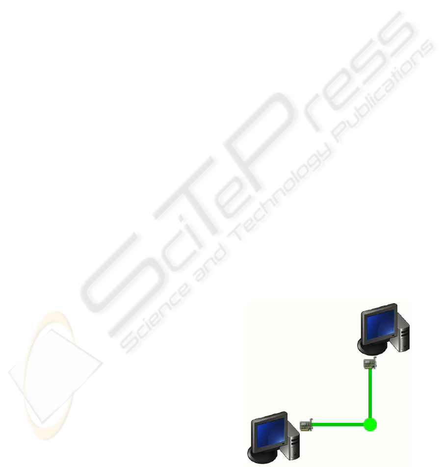
Figure 3 shows the network layout with two nodes
connected by Ethernet interfaces, as it is visualised in
the Verinec graphical editor.
Figure 3: Two nodes connected by Ethernet.
AUTOMATED CONFIGURATION DISTRIBUTION IN VERINEC
305
3 ADAPTION MODULE
After the design phase, we have the new configura-
tion in the Verinec XML format. It is tested to work
as desired and ready to be distributed to the network
machines. But how to tell our network devices about
it? Verinec offers the adaption module as a framework
to automate this process.
Verinec needs to know what implementation of a
service is being used in order the configure it prop-
erly. Thus, for applying the configuration we must
leave the abstraction level of not caring about vendor
specifics. We introduced a type system to add this
kind of device specific information into the node con-
figuration. The type system will be described in the
first subsection of this section.
We split the process into several steps to make it
more flexible. For every implementation of a service,
a specific translator is used to generate the appropri-
ate configuration information. Afterwards, a distrib-
utor matching the format of the generated configu-
ration data is used to apply the configuration to the
device.
The separation between translation and applying
the configuration is useful because the latter can be
implemented independent of the actual service. While
we need a specific translator for every implementation
of each service, fewer methods to distribute the con-
figuration are needed. Linux, Unix and *BSD servers
can be covered by placing a plain text configuration
file at the correct location in their file system. Sev-
eral Windows services can be configured using the
Windows Management Instrumentation (WMI). We
are implementing more distribution methods, e.g. for
Cisco routers, using SNMP to trigger the device to
download its new configuration.
To produce implementation specific configuration,
we have to leave the XML configuration abstraction.
This introduces the problem that some implementa-
tions of a service might not support everything that
can be defined in the abstract XML. To control the
situation, a restrictor produces warnings if features
are used which are not supported by the chosen im-
plementation.
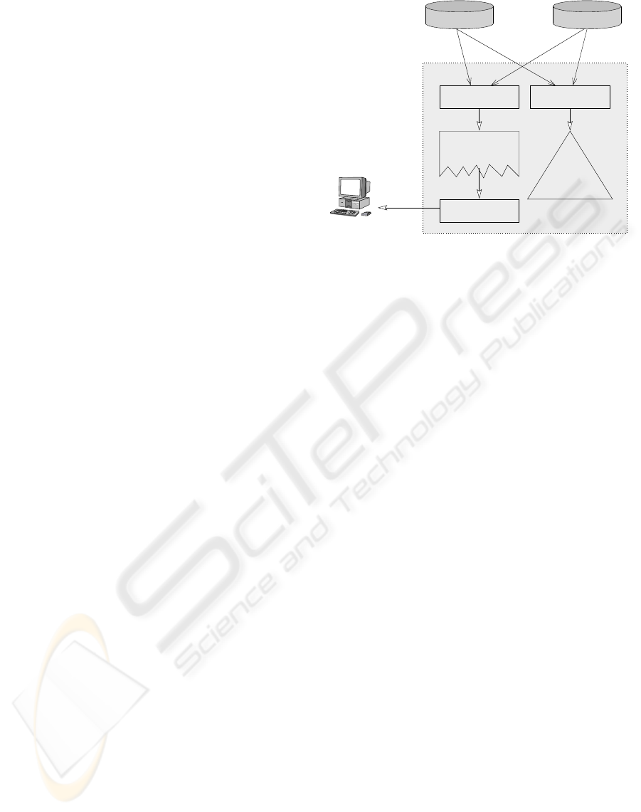
The adaption module is divided into the following
three steps:
• Restriction: Identifying features that are not sup-
ported by the chosen implementation.
• Translation: Generate data in an appropriate form
from the abstract XML.
• Distribution: Actually configure the nodes.
The configuration steps are shown in Figure 4 and
will be described in the Subsections 3.2 to 3.4.
Translate
Distribute
Restrict
Restriction
selected translator
warnings for
Configuration
Machine specific
XSL Repository
Network
Definition
Configuration
on Machines
Translator
Figure 4: Steps of the translation process.
3.1 Type system
A separate namespace allows to define node types and
distributors. Each node within the Verinec XML net-
work definition needs a type declaration with specifi-
cations for each service configured on that node. Fig-
ure 5 defines a node type for a machine running the
Redhat Linux distribution. The <tr:service />
tags specify the restrictor and translator to be used
with the service. The framework reads this type infor-
mation to select the correct restrictor and translator.
<tr:type name="linux-redhat" id="typ01">
<tr:service name="ethernet"
translation="linux-redhat" />
<tr:service name="dns" translation="bind8" />
</tr:type>
Figure 5: Node type definition.
Types are defined globally and can be referenced
within a node by their ID. If the node does not com-
pletely match the settings of its type, it is also pos-
sible to override the translator setting for that service
locally within the node.
3.2 Restriction step
The design of Verinec takes into account that some-
times, an implementation of a service does not sup-
port all features that can be expressed using the ab-
stract XML. A restrictor is an Extensible Stylesheet
Language Transformation (XSLT) (Clark, 1999) doc-
ument which extracts constructs from the configura-
tion data which are not usable with the chosen trans-
lator for the service. The restrictors produce human
readable explanations for each offending construct.
Every restrictor is bound to one translator, ensuring
ICETE 2005 - SECURITY AND RELIABILITY IN INFORMATION SYSTEMS AND NETWORKS
306

that the system produces the warnings specific to the
currently targeted implementation.
An improved handling of the restriction problem
would be to remove from the abstract configuration all
offending parts, so it could be completely translated
into the desired implementation format. This would
ensure that the verification process remains valid after
the translation of the configuration to the device.
Note that sometimes, even if a feature of the Ver-
inec configuration does not map one to one to a setting
in the configuration file, it might be possible to emu-
late it using a clever translation. If a test in a packet
filter does not exactly map to one statement, it might
still be possible to create a bunch of tests that result
in the same behaviour. The restrictor will only issue
warnings if a feature can not be emulated.
3.3 Translation step
The framework locates the appropriate translator for
a service and applies it to the node XML document.
The translators are, as the restrictors, transformation
documents expressed in the XSLT language. One
stylesheet generates configuration data for exactly
one implementation of a service. In Figure 5, the Eth-
ernet configuration will be created by the linux-redhat
translator, while the DNS server configuration can be
created by a standard translator for bind, as bind al-
ways has the same configuration file format in Linux
distributions.
The output is an XML document according to the
configuration schema. This schema allows to define
pre- and post-processes and contains tags to specify
the data for the distribution method.
The configuration document contains the data to be
given to the distributor, for example the content of
a plain text file (<result-file>) or XML doc-
uments (<result-xml>) that will be understood
by the distributor, e.g. a list of WMI commands ex-
pressed in XML. An example is given in Figure 6.
3.4 Distribution step
To distribute the configuration, we need to know what
method to use to access the target machine. The
<tr:target> element specified in the node type
definition and copied into the configuration document
contains a tag for the appropriate distribution method.
Each tag has the necessary attributes for its method,
for example the community string for SNMP or user-
name and key file for SSH.
The target in Figure 6 tells the framework to use the
secure copy
2
distribution method, opening an ssh con-
2
Scp is an application to securely copy files over a net-
work. It is part of the secure shell suite.
http://www.openssh.org/
<configuration>
<service name="hardware">
<tr:target name="copy to machine">
<tr:scp username="buchmand" host="diufpc55"
keyfile="/home/buchmand/.ssh/id_dsa" />
</tr:target>
<result-file filename="/etc/sysconfig/network-
skripts/ifcfg-eth0">
# Ethernet card configured by Verinec: ethernet 0
DEVICE=eth0
IPADDR=192.168.0.55
TYPE=Ethernet
ONBOOT=yes
</result-file>
</service>
</configuration>
Figure 6: Listing of configuration output.
nection to the specified host to copy the configuration
file there. If the host has our public key and supports
the public key authentication, no further information
is needed, otherwise we present the a password input
dialog. New targets can be defined for other distribu-
tion methods.
Distribution is achieved by Java implementations
of configuration protocols. The framework looks up
the distributor class using the <tr:target> ele-
ment. This class must implement the Java interface
IDistributor. The target tag is passed to the dis-
tributor together with the configuration result to dis-
tribute. The distributor can be as simple as writing the
text of <result-file> into a file at the specified
location. Or it can be as complex as an implementa-
tion of WMI in Java, retreiving and executing objects
from a remote machine.
When reconfiguring a service, we must take care
not to introduce temporary security risks. For exam-
ple, disabling a software firewall while we write the
configuration file could expose a machine to security
threats. Security implication of the transition have to
be carefully examined when writing adaption module
components.
4 DISCUSSION
There exist many protocols to manage networks.
SNMP is a veteran, but is used mainly for status mon-
itoring. Many device manufacturers do not support
actively configuring their devices by means of SNMP.
Besides some proprietary protocols, there are some
new open standards being developed. A quite promis-
ing work is being done by the NetConf working group
of the IETF. Their goal is to create a standard network
configuration protocol (Enns, 2004). Also of inter-
est is the DM (device management) part of SyncML
AUTOMATED CONFIGURATION DISTRIBUTION IN VERINEC
307

(Guru, 2003). SyncML DM is primarily addressed at
mobile devices, but could also be used for other de-
vices. Both projects only address the transport layer
of configuration data. The actual configuration data
will still be in proprietary format. While one distrib-
utor for each of the protocol will suffice, we will still
need a different translator for every implementation.
Another project is the Web Based Enterprise Man-
agement (WBEM) initiative of the Distributed Man-
agement Task Force (DMTF, 2005). It only tries
to achieve a common information model, which
would represent products from different vendors uni-
formly. We already support Microsoft’s implemen-
tation of WBEM, called WMI. However, experience
with WMI shows that it suffers the same problem as
SNMP: Many device settings are read only and can
not be changed via WMI.
Verinec is a framework with an open design. If
we need to support devices which can be configured
using the NetConf, WBEM or SyncML protocol, it
is possible to add support for them. As all those
projects chose an XML format for their protocol, cre-
ating commands from the Verinec XML configuration
data should be rather straightforward.
Many attempts have been made to build network
configuration solutions. Service providers can choose
from specialised tools to administrate large numbers
of routers (Cisco, 2005), (Wandl, 2005). There exist
projects like Splat (Abrahamson et al., 2003) that fo-
cus on one aspect of organisation and enterprise net-
works: the edge devices. However, organisation and
enterprise networks are a lot more heterogeneous than
service providers infrastructures.
Verinec is an open framework. It can support all
kind of different devices. Where it does not already
support a device, it is relatively easy to add support.
There are projects that require the user to define
the network configuration from scratch, for exam-
ple (Bellogini and Santarelli, 2004). Others focus on
analysing existing networks (Hewlett-Packard, 2005),
(IBM, 2005), (Toledo, 2005) but do not have the ca-
pability to directly configure devices.
Verinec aims at joining the two worlds. One can
analyse the existing network, edit the retrieved con-
figuration and reconfigure the devices in the network
within one single system.
However, the most important plus of Verinec com-
pared to other existing solutions is the runtime ver-
ification module to ensure proper functioning of the
network (Jungo et al., 2005) and (Jungo, 2004).
4.1 Plans for the future
There is a lot of work ahead for Verinec to become
really useful. Among others, the following points
should be addressed:
• To make Verinec usable in practice, it is important
to support as many network device vendors and ser-
vice implementations as possible. Currently, there
are only a few translators available to allow testing
the application.
• At the writing of this paper, Verinec supports only
TCP/IP networks. It is planned to implement sup-
port for other network types, for example IPX or
MPLS.
• The automatic distribution of configuration data re-
quires that Verinec can access all nodes. Some-
times, a firewall or router might prevent this. It
would be interesting to see if we can develop a
module to solve such issues and i.e. temporarily
open a hole in a firewall allowing the configuration
process to work but keep the security risk as small
as possible.
3
• One task of a network management tool is to moni-
tor the network behaviour. We could use the JRobin
project (Markovic and Vandamme, 2005) to gather
statistics of the network operations and present
them within Verinec. We could also think of cre-
ating alerts if something does not run as it was sup-
posed to.
4.2 Conclusion
In this paper, we presented a centralised approach to
network configuration. Verinec is a configuration tool
that “knows” about the whole network and can ensure
its correct functioning prior to applying configuration
updates.
The modular design allows to add new functional-
ity easily around the common core of the XML net-
work definition. The adaption module is designed to
be extended to new devices in a simple manner, giving
the tool great flexibility.
The centralised configuration approach has several
advantages over the dispersed configuration of indi-
vidual devices:
• Verifiable consistent configuration.
• No illegal configuration, syntactically correct but
dangerous configurations can be detected.
• Accurate documentation of the network’s setup.
• Automated configuration of many machines.
• One tool to configure the whole network. The ad-
ministrator does not need to learn the particularities
3
When we consider the transition of the whole network
from an old configuration to the new one, we enter the do-
main of temporal questions: How is the network currently
configured? In which order should we configure the nodes
so to minimise network outages during transition and never
to lock the machine running Verinec out?
ICETE 2005 - SECURITY AND RELIABILITY IN INFORMATION SYSTEMS AND NETWORKS
308

of several similar machines and their configuration
tools from different vendors.
• If a node in the network breaks, it can be replaced
and the configuration reapplied. It is even possible
to use a machine from a different vendor without
having to reenter the configuration.
Altogether, these points help to increase reliability
and security of a network and facilitate the life of net-
work administrators.
However, we should not forget about some disad-
vantages. Verinec introduces an additional layer of
software between machines and administrators. We
should keep in mind some points to avoid introducing
new problems and maybe compromising the network
security:
• Automatic generation of configuration instruction
makes live easier – as long as it is done correctly.
Special care must be given to make the translation
of XML into the vendor specific format as accurate
as possible.
• If Verinec is to be used in a real world environment,
we need to do performance testing. We do not yet
know how long it would take to configure a com-
plete network. One improvement regarding the du-
ration of the transition state of the network would
be to parallelise configuration commands to inde-
pendent machines.
• The Verinec XML format does not cover all spe-
cific features found in service implementations, but
focus on the common parts. There is always a
compromise to achieve between many features and
portability from one implementation to the other.
Highly optimised configurations will be difficult to
achieve using a configuration generation tool like
Verinec.
The centralised approach is less flexible to work
with, as all changes must be done to the central repos-
itory. This could lower the acceptance by system ad-
ministrators. If they would start to configure some
devices from outside the Verinec system, the incon-
sistency risks would rise again. To make it possible to
use Verinec from different locations, we could think
of a server/client approach, for example with a Java
applet as client to access the Verinec system with a
web browser.
REFERENCES
Abrahamson, C., Blodgett, M., Kunen, A., Mueller, N., and
Parter, D. (2003). Splat: A network switch/port con-
figuration management tool. In Seventeenth Systems
Administration Conference (LISA 03), Berkeley, CA,
USA. Usenix.
Barringer, H., Goldberg, A., Havelund, K., and Sen, K.
(2004). Rule-based runtime verification. In Proceed-
ings of Fifth International VMCAI conference (VM-
CAI’04). Springer.
Bellogini, A. and Santarelli, I. (2004). Network markup
language. Technical report, Roma Tre University,
http://giga.dia.uniroma3.it/ ivan/NetML/.
Charles, P. (2001–2005). Jpcap. Technical report,
http://jpcap.sourceforge.net.
Cisco (2005). Internet operation system. Technical report,
Cisco Systems, http://www.cisco.com.
Clark, J. (1999). Xsl transformations (xslt). Technical re-
port, W3C, http://www.w3.org/TR/xslt.
DMTF (1996-2005). Web-based enterprise man-
agement (wbem) initiative. Technical report,
http://www.dmtf.org/standards/wbem/.
Enns, R. (2004). Netconf configuration protocol.
Technical report, Internet Engineering Task Force,
http://www.ops.ietf.org/netconf/.
Fyodor (1997–2005). Network mapper. Technical report,
http://www.insecure.org/nmap/.
Guru, R. (2003). Syncml device management. Technical
report, IBM India Software Labs, http://www-
106.ibm.com/developerworks/wireless/library/wi-
syncml1/.
Hewlett-Packard (2005). Hp openview. Techni-
cal report, Hewlett-Packard Development Company,
http://www.managementsoftware.hp.com.
IBM (2005). Ibm tivoli netview. Technical re-
port, International Business Machines Corp.,
http://www.ibm.com/software/tivoli/products/netview/.
Jungo, D. (2004). The role of simulation in a network con-
figuration engineering approach. In ICICT 2004, Mul-
timedia Services and Underlying Network Infrastruc-
ture, Cairo, Egypt. Information Technology Institute.
Jungo, D., Buchmann, D., and Ultes-Nitsche, U. (2005).
A unit testing framework for network configurations.
In Proceedings of the 3rd International Workshop on
Modelling, Simulation, Verification, and Validation
of Enterprise Information Systems (MS VVEIS 2005),
Miami, Florida, USA. INSTICC Press.
Markovic, S. and Vandamme, A. (2003–2005). Jrobin:
Rrdtool choice for the java world. Technical report,
jrobin.org, http://www.jrobin.org/.
Toledo, J. (2000–2005). Etherape. Technical report,
http://etherape.sourceforge.net.
Ultes-Nitsche, U., Jungo, D., and Buchmann, D.
(2004–2005). Verified network configura-
tion. Technical report, University of Fribourg,
http://diuf.unifr.ch/tns/projects/verinec/.
Wandl (2005). Ip analysis tool. Technical report, Wide
Area Network Design Labroratory, http://www.
wandl.com/html/ipat/IPAT
new.cfm.
AUTOMATED CONFIGURATION DISTRIBUTION IN VERINEC
309
