
SHARING SERVICE RESOURCE INFROMATION FOR
APPLICATION INTEGRTATION IN A VIRTUAL ENTERPRISE
Modeling the communication protocol for exchanging service resource information
Hiroshi Yamada, Akira Kawaguchi
NTT Service Integration Laboratories, 9-11, Midori-Cho, 3-Chome, Musashino-Shi, Tokyo, 180-8585, Japan
Keywords: Resource sharing, Protocol modeling, Business integration, EAI, Grid computing, Web service
Abstract: Grid computing and web service technologies enable us to use networked resources in a coordinated
manner. An integrated service is made of individual services running on coordinated resources. In order to
achieve such coordinated services autonomously, the initiator of a coordinated service needs to know
detailed service resource information. This information ranges from static attributes like the IP address of
the application server to highly dynamic ones like the CPU load. The most famous wide-area service
discovery mechanism based on names is DNS. Its hierarchical tree organization and caching methods take
advantage of the static information managed. However, in order to integrate business applications in a
virtual enterprise, we need a discovery mechanism to search for the optimal resources based on the given a
set of criteria (search keys). In this paper, we propose a communication protocol for exchanging service
resource information among wide-area systems. We introduce the concept of the service domain that
consists of service providers managed under the same management policy. This concept of the service
domain is similar to that for autonomous systems (ASs). In each service domain, the service information
provider manages the service resource information of service providers that exist in this service domain.
The service resource information provider exchanges this information with other service resource
information providers that belong to the different service domains. We also verified the protocol’s behavior
and effectiveness using a simulation model developed for proposed protocol.
1 INTRODUCTION
Integrated services using grid and web service
technologies are increasing. Using these
technologies, we can orchestrate several business
applications and share more resources in the network
autonomously. In an enterprise or a virtual
enterprise, EAI (enterprise application integration)
tools are used to integrate several applications and
resources in the enterprise network. This service
architecture needs to define mechanisms for creating,
naming, and discovering transient service instances.
In addition, it also needs to provide location
transparency and multiple protocols for binding a
service instance. That is the initiator of the
integrated service or resource-sharing service has to
be able to answer questions such as: “which server is
the target application with the name “A” running
on”, “which server has sufficient CPU power to deal
with our request”, and “which server has the lighted
load?.”
In the above architecture, the information service
should be designed to support the initial discovery
and ongoing monitoring of the existence and
characteristics of resources, services, computations,
and other things. Hereafter, we call these
characteristics service resource information (SRI).
Some SRI may be static and long-lived while other
service information may be highly dynamic. For
example, computation specifications like CPU
power, operating system name, and memory size are
static SRI, but the CPU load of the application
server is highly dynamic SRI.
109
Yamada H. and Kawaguchi A. (2005).
SHARING SERVICE RESOURCE INFROMATION FOR APPLICATION INTEGRTATION IN A VIRTUAL ENTERPRISE - Modeling the communication
protocol for exchanging service resource information.
In Proceedings of the Second International Conference on e-Business and Telecommunication Networks, pages 109-116
DOI: 10.5220/0001408801090116
Copyright
c
SciTePress

The most successful and famous wide-area
service resource discovery mechanism is the domain
name service (DNS). This is based on server names.
Its hierarchical tree-like organization and caching
methods take advantage of rather static information
like names. However in grid computing and web
service environments, the initiator of the integrated
services requires specific sets of service information
attributes, for example, the application name, and
required operating system in order to provide the
optimum service quality. The scheduling policy
engine can calculate and determine the appropriate
set of required service resources using the SRI
obtained by the discovery mechanism. In particular,
dynamic service resource information like CPU load
is one of the important parameters. Unlike the
discovery mechanism using static service resource
information, the search mechanism using dynamic
SRI can benefit from a certain degree of
approximation. For example, such a discovery
mechanism can search for the server whose CPU
load is less than 30% or idle disk space is larger than
6MB.
This paper is organized as follows. Related
work about discovery of SRI is summarized in
Section 2. Several concepts that define the
architecture for systematically exchanging SRI are
introduced in Section 3. Using a simulation model
developed for the proposed protocol (Yamada, 2004),
we verify the protocol’s behavior and effectiveness
in a case study in Section 4. Section 5 summarizes
the proposed protocol and mentions further studies.
2 RELATED WORK – DISCOVERY
OF SRI
SRI discovery mechanisms based on static resource
attribute like a file name are discussed in P2P
computing environments. In P2P computing, SRI is
used to search for the server location. There are
various searching mechanisms. For example,
Gnutella (Gnutella) uses flooding method. Freenet
(Clarke et al, 2000) uses a combination of informed
request forwarding and file replication methods.
These discovery methods are based on static SRI.
The decentralized resource discovery method in
the grid environment is discussed in (Iamnitchi et al,
2001). The basic framework of this discovery
mechanism is the request-forwarding mechanism. In
this framework, one or two SRI providers are
considered and the provider server is called a peer or
node. A virtual organization has one or two nodes.
Each node can store service resource information
and provide service information about one or more
resources. The initiator of the coordinated service
sends a request to the node. The node responds with
the matching service resource description if it has
the requested service information. Otherwise, the
node forwards the SRI request to other nodes. If a
node can respond to the request, it directly answers
the initiator. This framework needs a membership
protocol. Each node should know the other nodes to
which it forwards requests when it cannot respond.
In Web services, UDDI (Universal Description,
Discovery, and Integration) (UDDI) is the
information provider. The service provider registers
the service information including the XML code
(WSDL (Web services description language
(WSDL)) access the service provider. The
requester first accesses UDDI and learns how to
access the target service provider. A quantitative
study of the information service is the starting point.
The grid information service architecture was
proposed in (Czajowski et al, 2001). It consists of
two components: highly distributed service
information providers and specialized aggregation
directory service providers. The information
provider deals with dynamic information about grid
resources and the aggregate directory service
provider deals with static information. The
information provider sends a registration message to
the aggregate directory. Communication among
different aggregate directory providers and among
different information providers is not explicitly
considered. The service information flow follows a
tree structure.
One example of a resource information service is
the network weather service (NWS) (Wolski, 1997).
In this service, several sensors are implemented in
nodes or links in the network and they monitor
resource consumption. The collected sensory data is
sent to the central database. The data is analyzed by
several statistical methods. The central database
corresponds to the information provider.
In the discovery mechanism proposed in this
paper, the service resource information providers
exchange SRI each other. We also regard the SRI
provider as the nodes in (Iamnitchi et al, 2001). We
introduce the concept of the service domain like that
in autonomous systems (ASs) in BGP (border
gateway protocol). A virtual enterprise has several
service domains. The application service providers
are managed in one service domain. The SRI
provider stores the static and dynamic SRI of all
service providers in the service domain. The SRI
provider establishes connections between
ICETE 2005 - GLOBAL COMMUNICATION INFORMATION SYSTEMS AND SERVICES
110

neighboring SRI providers in different service
domains. The initiator of a coordinated service
sends a request to the SRI provider. Because the
service information provider exchanges the SRI with
other SRI providers, it can responds to the request.
The exchange of SRI is similar to the exchange of
NLRI (Network Layer Reachability Information) in
BGP.
3 ARCHITECTURE MODEL
3.1 Overview
In this paper, we consider three players: SRI
provider, service provider, and requester (the
initiator of the coordinated service). The service
provider is the server that provides the application
services, for example, processing the requester’s
computation or providing the files. The SRI
provider is the server that manages the SRI of the
service providers and exchanges the service resource
information about the managing service providers
with other service resource information providers.
The requester asks the service resource information
provider, obtains the service resource information,
and decides which server it should access based on
the obtained service information and the scheduling
rule, and finally accesses the service provider where
the target application service is running.
In grid computing, two protocols are used: grid
information protocol (GRIP) and grid registration
protocol (GRRP) (Czajowski et al, 2001). GRIP is a
protocol for looking up SRI and discovering the
appropriate server. The requester uses it. GRRP is a
protocol for sending the service information from
the service provider to the SRI provider.
In (Czajowski et al, 2001), the following
architecture is considered. This architecture has
information providers and aggregate directory
service providers. The service resource information
provider manages the SRI about several service
providers. The aggregation directory service
providers communicate with the SRI provider and
manage the aggregated service information. The
requester can ask either provider. In this
architecture, communication among different
information providers and among the aggregate
directory service providers is not explicitly
considered.
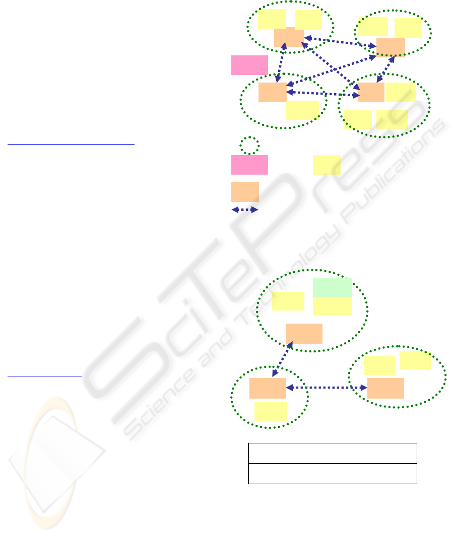
In this paper, we consider the architecture shown
in Figure 1. The SRI providers manage the SRI
about all service providers in the service domain and
communicate with other SRI providers in order to
exchange the SRI that each service provider
manages. The requester can access a nearby SRI
provider and ask for a SRI of the service provider
that can provide the application service that the
requester desires. Let us call the communication
protocol between the SRI providers service domain
information protocol (SDP).
Here we introduce the concept of the service
domain (SD), like that in anonymous systems (ASs)
in BGP, which is defined as a group of service
providers. The information provider is the
representative of the service domain. A unique
number is assigned to the service domain. Let us
call it the service domain number. The SRI provider
communicates with all the service providers. The
service provider registers the SRI and reports the
current load status (a dynamic resource attribute) in
order to update the registered SRI. If the service
provider stops providing the registered service, a
request to discard the SRI is sent to the SRI
provider. The SRI provider also communicates with
the other SRI providers to exchange SRI with them.
Let us call a peer for exchanging service information
a neighbor.
SDP can control and modify service resource
information and associated attributes. For example,
if the service resource information provider requires
that a neighboring SRI provider does not forward the
received SRI to any other information providers,
then SDP stops it being forwarded.
This mechanism is similar to the control scheme in
BGP. In BGP, the device manager can configure the
route map in order to control the forwarding route
information. Because the scheme for exchanging
SRI is based on BGP, SDP can also control the SRI.
SDP creates and maintains the SRI base (SIB) in the
SRI provider. When this SRI provider receives an
update message from a neighboring SRI provider, it
updates its SIB table. Figure 2 shows an example.
SD_path is included as one of the associated path
attributes. This shows the service domain numbers
for delivering the registered service resource
information. For example, an application called
“AP_1” is running on service provider “SP3”. This
SRI is created in the SRI provider with service
domain number 3. This service information is
delivered via service domains 3, 2, and 1 to “IP_1”.
SHARING SERVICE RESOURCE INFROMATION FOR APPLICATION INTEGRTATION IN A VIRTUAL
ENTERPRISE - Modeling the communication protocol for exchanging service resource information
111

3.2 Service domain information
protocol
Like BGP, SDP first tries to establish connections
with neighbors listed in the configuration file. The
procedure for establishing an SDP connection is the
same as that in BGP. First, the OPEN message is
exchanged. Then, the KEEPALIVE message is
exchanged. Finally, the UPDATE message
containing the service resource information is
exchanged and the SRI provider updates the local
SRI base (SIB). Once the SDP connection has been
established, UPDATE and KEEPALIVE messages
are exchanged between neighbors when there is and
is not, respectively, new SRI.
The SDP UPDATE message has a service
information field instead of the network layer
reachability information (NLRI) field in the BGP
UPDATE message. This field stores the service
information including the application name, CPU
power level, and CPU load status. The static SRI is
configured in SDP. The configured SRI is
exchanged through the SDP connection with other
SRI providers. This mechanism is the same as the
NLRI in BGP. On the other hand, dynamic SRI is
also exchanged. When the CPU load status in the
service provider is changed, the service provider
reports the current SRI that needs to be updated.
This SRI is set in the service information field in the
SDP UPDATE message and is exchanged among
neighbors. In BGP, the network route information
redistributed from interior gateway protocol (IGP,
e.g., OSPF and IGRP) is dynamically set in the
NLRI field in the BGP UPDATE message. The
neighbors that receive the SDP UPDATE message
also update their SIB and send the updated service
resource information to their neighbors.
The path attributes are also considered in SDP
protocol like in BGP. They are used to select the
appropriate SRI among multiple entries in SIB.
These entries have the same information about the
application name and server names and IP address
but they have different path attributes. In the current
version of the developed simulation SDP model, the
following are considered as SDP path attributes:
origin, SD path, community, and local preference.
Here, the origin means how to obtain the service
information and has two values: “DFP” or “ESDP”.
“DFP” means that the SRI is obtained from the
service provider by the registration protocol or is
statically configured in the SRI provider. “ESDP”
means that the SRI is obtained from another SRI
provider. The SD path means the set of SD
numbers of the service domain along which the SDP
UPDATE message traverses from the original
information provider to this information provider.
The local preference means the preference of the
original SRI provider. The SRI selection rule is
defined as follows in the current version. First, path
attributes preferences are compared. The SRI entry
that has the larger preference value is selected.
Second, if the preference values are the same, the
lengths of the SD path attributes are compared. The
SRI entry with its shorter SD path is selected. If the
SD path lengths are also the same, the values of the
origin are compared. Here, we select the SRI entry
with “DFP” rather than that with “ESDP”. If the
SRI entries have the same values for the above
condition, finally, we compare the identifiers of the
advertising SRI providers. The SRI providers have
unique identifiers. In this model, the largest value
among the IP addresses of the interfaces is assigned
as the SRI provider identifier. The SRI entry that is
advertised by the highest SRI provider identifier is
selected. We can consider several alternative rules
for selecting the SRI entries. And the path attribute
can be modified in the SRI provider when the SRI
provider exchanges service resource information
with neighbors as in BGP protocol. A sophisticated
scheme for controlling the path attributes is for
further study.
4 CASE STUDY
In order to verify and analyze the protocol behavior
and effectiveness, we developed a simulation model
of proposed protocol by OPNET (Yamada, 2004).
Using this simulation model, we considered the
following virtual enterprise system.
4.1 Network model
In this case study scenario, three companies that
have their own networks decide to make a virtual
enterprise, as shown in Figure 3. The core network
is created and these companies’ networks are
connected to the core network. The routing
architecture is as follows. The OSPF routing
protocol with each different tag number is running
on each company’s network. In the core network,
OSPF routing protocol is also running. Each
company’s network has a different AS number. The
AS numbers of networks 178.0.0.0/8, 192.0.0.0/8,
and 200.0.0.0/8, are 100, 300, and 200, respectively.
In the edge routers of each network, BGP protocol is
configured. Exterior BGP (EBGP) connections are
established between the edge routes in each network
and the core network. The Interior BGP connections
are fully meshed among edge routers in the core
ICETE 2005 - GLOBAL COMMUNICATION INFORMATION SYSTEMS AND SERVICES
112

network. The redistribution command is configured
in the edge routers of each company’s network. The
outside routes obtained by BGP protocol are
redistributed into ones by OSPF routing protocol and
the routes in the company’s network are also
redistributed into ones by BGP protocol.
Synchronization is off in the BGP configuration.
The SRI and router node are connected by RIP
protocol. In order that each is reachable from others,
redistribution is also done in the router. The SRI
provider is located for each service domain as in the
following table.
4.2 Service domain configuration
Each company’s network has two service domains.
Their service domain numbers are 1780 and 1781
for network 178.0.0.0/8, 1920 and 1921 for network
192.0.0.0/8, and 2000 and 2001 for network
200.0.0.0/8.
SDP connections are established among the SRI
providers in a fully meshed manner.
Table 1: Service resource information provider
Name Interface IP
address
Local
SD
Local
AS
service_manager_0 178.0.100.2 1780 100
service_manager_1 178.0.101.2 1781 100
service_manager_2 192.0.60.2 1920 300
service_manager_3 192.0.61.2 1921 300
service_manager_4 200.0.60.2 2000 200
service_manager_5 200.0.61.2 2001 200
4.3 Service resource information
In this case study, we considered the two types of
the SRI: static and dynamic information. The SRI
attributes are service provider’s IP address, running
application name, CPU power, and CPU load in this
scenario.
The static SRI that each service resource
information provider maintains is shown in Table 2.
Here, the CPU load was fixed at time of the
configuration and does not change. The dynamic
service resource information was modeled as
follows. Except for the CPU load, the other
attributes were configured as shown in Table 3.
In this case study, the CPU load for the dynamic
SRI is modeled as follows. We considered that the
service resource update notification for dynamic
resource information occurred according to some
stochastic distribution (in numerical results, we
considered the Poisson process). In order to
determine the CPU load at the epoch of the update
notification, we also configured the upper and lower
bounds. If the outcome of the uniform distribution
was less than the lower bound, the CPU load was
low (L). If it was larger than the upper bound, the
CPU load was high (H). Otherwise the CPU load
was medium (M). If the CPU level changed from
the previous level, an update message was created
and exchanged among other SRI providers.
Table 2: Static service resource information
entry
Server IP
address
(manager #)
Running application
names
CPU
power/
load
178.0.120.10(0) ap_1, ap_2, ap_3, ap_4 H/H
178.0.121.20(0) ap_4, ap_6 M/M
178.0.102.10(1) ap_1 L/L
178.0.103.10(1) ap_2, ap_3 H/M
192.0.110.10(2) ap_7, ap_8, ap_10 M/H
192.0.111.11(2) ap_2 H/L
192.0.112.10(2) ap_3, ap_8, ap_9 H/M
192.0.140.10(3) ap_1 L/L
192.0.141.20(3) ap_7, ap_8 H/M
192.0.142.10(3) ap_3, ap_5 M/H
200.0.90.10(4) ap_1, ap_4, ap_6, ap_8 H/H
200.0.91.20(4) ap_4 L/L
200.0.80.10(5) ap_2, ap_11, ap_12 H/L
200.0.81.10(5) ap_5, ap_13 L/M
Table 3: Dynamic service resource information
entry
Server IP
address
(manager #)
Running application
names
CPU
power
178.0.126.1(0) ap_31, ap_32 M
178.0.127.11(0) ap_33, ap_35 H
178.0.128.20(0) ap_34 L
178.0.129.22(0) ap_36 M
178.0.52.10(1) ap_41 L
178.0.53.10(1) ap_42 H
178.0.54.20(1) ap_43 H
192.0.130.10(2) ap_57, ap_58, ap_59 M
192.0.131.11(2) ap_52 H
192.0.132.10(2) ap_53, ap_58, ap_59 H
192.0.150.10(3) ap_61 L
192.0.151.20(3) ap_67, ap_31 H
192.0.152.10(3) ap_32, ap_35 M
200.0.95.10(4) ap_41, ap_34, ap_53,
ap_58
H
200.0.96.20(4) ap_61 L
200.0.85.10(5) ap_57, ap_32, ap_58 H
200.0.86.10(5) ap_59, ap_43 L
SHARING SERVICE RESOURCE INFROMATION FOR APPLICATION INTEGRTATION IN A VIRTUAL
ENTERPRISE - Modeling the communication protocol for exchanging service resource information
113

4.4 Exchanging the service resource
information
In the simulation experiment, we considered the
following scenarios. Here, we set the mean value of
the update notification interval is 15 and 30. The
lower and upper bound were set to 0.3 and 0.6,
respectively.
Here, we focused on the SRI table maintained in
service_manager_0. Table 4 shows the part of the
SRI in the service_manager_0. We focused on the
entries of ap_3. This resource information was
statically configured in the SRI provider. Because
these entries were statically configured, their CPU
load attributes did not change. There were four
entries. The service provider is selected among
these four entries based on the selection rule.
Next, table 5 shows part of the table at 300, 400
and 800. Here we focused on the entries of
application, ap_32. There were three entries for
ap_32 in these tables. This application was
dynamically registered in the SRI provider, so, the
CPU load attribute of these entries varied. If the
policy for selecting the service provider was that a
lower CPU load and higher CPU power were the
best, then at 300, the requester selected 178.0.126.1.
At 400, the requester selected 200.0.85.10. And at
800, if the requester’s policy gave priority to the
CPU power, then 200.0.85.10 was selected. Of
course, we can consider the various selection
policies.
Let us consider the case where the SRI provider
with the service domain 2001 wants to reject access
from requesters in outside networks. Then, this
service resource provider sends an update message
in which the CPU load attribute in server
200.0.85.10 is set to “H”. So, the other SRI provider
receives the message and set the CPU load attribute
to “high”. Therefore, the requesters in an outside
network can never access server 200.0.85.10. Using
this service information discovery mechanism, the
manager of the virtual enterprise system can
configure the strategic policy to block the access.
Table 4: Service resource information table
(We focus on ap_3.)
IP address CPU
power
CPU
load
Source
protocol
SD
path
192.0.112.10 H M ESDP 1920
192.0.142.10 M H ESDP 1921
178.0.103.10 H M ESDP 1781
178.0.120.10 H H SDP -
Table 5: Service resource information table
(We focus on ap_32.) At 300
IP address CPU
power
CPU
load
Source
protocol
SD
path
192.0.152.10 M M ESDP 1921
200.0.85.10 H H ESDP 2001
178.0.126.1 M L SDP -
At 400 seconds
IP address CPU
power
CPU
load
Source
protocol
SD
path
192.0.152.10 M H ESDP 1921
200.0.85.10 H L ESDP 2001
178.0.126.1 M H SDP -
At 800 seconds
IP address CPU
power
CPU
load
Source
protocol
SD
path
192.0.152.10 M H ESDP 1921
200.0.85.10 H H ESDP 2001
178.0.126.1 M M SDP -
4.5 Update traffic
Figure 4 shows the sent traffic generated by this
protocol from the service_manager_0 in this case
study scenario. When we set the mean value of the
update notification interval to 15, the generated
traffic was larger than that when the mean was 30.
When the lower and upper bounds were set to 0.2
and 0.9, that is when the frequency of CPU load
status changes was low, the generated traffic was the
smallest. The update traffic generated by this SDP
protocol depended on the registered SRI, update
notification frequency, number of the neighbors, and
strategic policy.
5 CONCLUSION
In order to coordinate several applications and share
service resources autonomously, a service that
provides SRI is important in grid computing and
Web service environments. This paper presented a
communication protocol for exchanging SRI among
wide-area systems and showed its behaviour using a
simulation model. This communication protocol is
based on BGP. In future, we will expand its
attributes and introduce several strategic policies for
exchanging SRI. We plan to extend the protocol
that exchanges SRI among IP peers in a further
study. To reduce the number of SDP sessions,
hierarchical architecture and functions are useful for
dealing with the scalability issue. In the BGP, the
route reflector mechanism reduces the number of
iBGP sessions and enables us to make a scalable
ICETE 2005 - GLOBAL COMMUNICATION INFORMATION SYSTEMS AND SERVICES
114
network. We plan to expand our proposed SRI
exchanging protocol, which has the same
mechanism as the route reflector in the BGP. The
created SRI table is used to determine which server
is appropriate for the request. We will develop a
simulation model that autonomously simulates the
application integration according to the business
process. We will develop modeling to evaluate
service performance when this protocol is applied to
the application orchestration system.
REFERENCES
Gunutella protocol specification,
http://www.clip2.com/articles.html
.
Clarke, I., Sandberg, O., Wiley, B. and Hong, T., 2000. A
distributed anonymous information storage and
retrieval system, In Workshop on Design Issues in
Anonymity and Underservability.
Czajowski, K., Fitzgerald, S., Foster, I., and Kesselrnan,
C., 2001. Grid Information Services for Distributed
Resource Sharing, 10
th
IEEE International Symposium
on High-Performance Distributed Computing (HPDC-
10), IEEE press.
Iamnitchi, A., and Foster, I., 2001. On fully decentralized
resource discovery in grid environments, Proceedings
of the Second International Workshop on Grid
Computing 2001.
Wolski, R., 1997. Forecasting network performance to
support dynamic scheduling using the network
weather service, Proceedings of the 6
th
IEEE
symposium on High Performance Distributed
Computing, Portland, Oregon, IEEE Press.
Universal description discovery and integration (UDDI),
http://www.uddi.org
.
Web Services Description Language (WSDL),
htpp://www.w3.org/TR/wdsl.
Yamada H., 2004. OPNET modeling of the protocol to
register and circulate service information, Proceedings
of OPNETWORK2004, Washington DC, August 2004.
William, P., 2001. Cisco BGP-4 command and
configuration handbook, Cisco Systems.
Figure 1: Architecture
Figure 2: SD_path
I
I
P
P
_
_
3
3
S
S
P
P
3
3
S
S
P
P
S
S
P
P
S
S
D
D
n
n
u
u
m
m
b
b
e
e
r
r
:
:
3
3
S
S
D
D
n
n
u
u
m
m
b
b
e
e
r
r
:
:
2
2
S
S
D
D
n
n
u
u
m
m
b
b
e
e
r
r
:
:
1
1
A
A
P
P
n
n
a
a
m
m
e
e
S
S
P
P
n
n
a
a
m
m
e
e
S
S
D
D
_
_
p
p
a
a
t
t
h
h
A
A
P
P
_
_
1
1
S
S
P
P
3
3
3
3
2
2
1
1
S
S
e
e
r
r
v
v
i
i
c
c
e
e
r
r
e
e
s
s
o
o
u
u
r
r
c
c
e
e
i
i
n
n
f
f
o
o
r
r
m
m
a
a
t
t
i
i
o
o
n
n
t
t
a
a
b
b
l
l
e
e
o
o
n
n
I
I
P
P
_
_
1
1
A
A
P
P
_
_
1
1
I
I
P
P
_
_
1
1
I
I
P
P
_
_
2
2
S
S
P
P
S
S
P
P
R
R
e
e
q
q
I
I
P
P
I
I
P
P
I
I
P
P
I
I
P
P
S
S
P
P
S
S
P
P
SP
S
S
P
P
S
S
P
P
S
S
P
P
S
S
P
P
S
S
P
P
R
R
e
e
q
q
I
I
P
P
S
S
P
P
Service domain
Requester
Service resource information provider
Service provider
Neighbor relationship
SHARING SERVICE RESOURCE INFROMATION FOR APPLICATION INTEGRTATION IN A VIRTUAL
ENTERPRISE - Modeling the communication protocol for exchanging service resource information
115
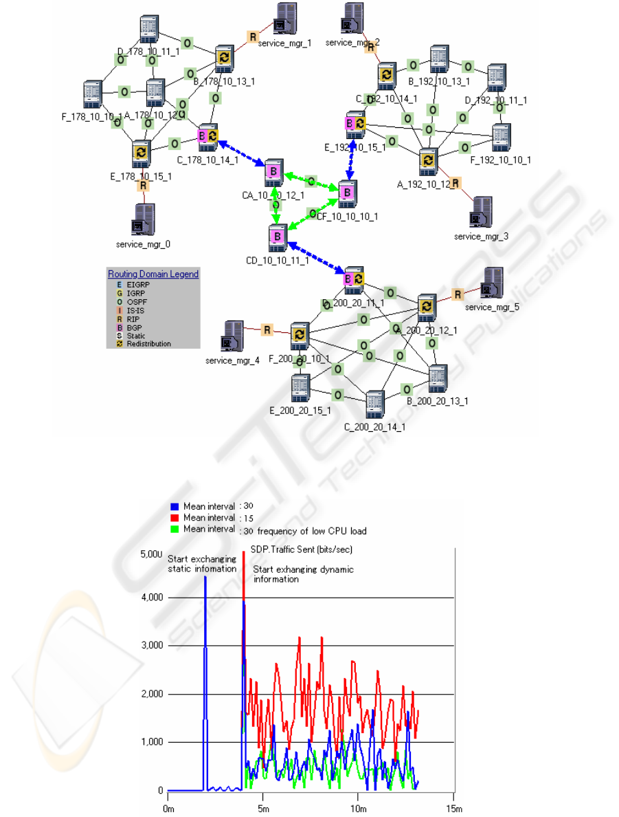
Figure 3: Case study network.
Figure 4: Traffic sent from service_mgr_0.
ICETE 2005 - GLOBAL COMMUNICATION INFORMATION SYSTEMS AND SERVICES
116
